User Guide
Page 14
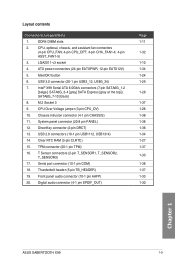
Package contents Check your motherboard package for the following items User Manual ASUS SABERTOOTH X99 motherboard Technical documentations, certification and warranty card Support DVD 6 x Serial ATA 6.0 Gb/s cables 1 x ASUS SLI™ bridge connector (12 cm) 1 x ASUS Q-Shield 1 x 2-in-1 ASUS Q-Connector kit 1 x 40 mm Assistant fan 4 x DRAM slot covers 2 x PCIe x16 slot covers 1 x PCIe x1 slot covers 1 x PCIe...
Package contents Check your motherboard package for the following items User Manual ASUS SABERTOOTH X99 motherboard Technical documentations, certification and warranty card Support DVD 6 x Serial ATA 6.0 Gb/s cables 1 x ASUS SLI™ bridge connector (12 cm) 1 x ASUS Q-Shield 1 x 2-in-1 ASUS Q-Connector kit 1 x 40 mm Assistant fan 4 x DRAM slot covers 2 x PCIe x16 slot covers 1 x PCIe x1 slot covers 1 x PCIe...

User Guide
Page 17
... for the Intel® Core™ i7 processors. SATA Express support SATA Express provides faster data transfer speeds of the SSDs. Chapter 1 ASUS SABERTOOTH X99 1-1 Intel® X99 Express Chipset Intel® X99 Express Chipset is the PCI Express bus standard that provides twice the performance and speed of the latest graphics technologies. It utilizes...
... for the Intel® Core™ i7 processors. SATA Express support SATA Express provides faster data transfer speeds of the SSDs. Chapter 1 ASUS SABERTOOTH X99 1-1 Intel® X99 Express Chipset Intel® X99 Express Chipset is the PCI Express bus standard that provides twice the performance and speed of the latest graphics technologies. It utilizes...
User Guide
Page 19
... eliminates buzzing noise and vibration, and delivers better performance, and durability during the most extreme usage. 1.1.4 "Safe & Stable!" Chapter 1 ASUS SABERTOOTH X99 1-3 Dust Defenders Dust Defenders provides rear I /O shield provide four times better protection and ensure the motherboard's lifespan. TUF Components (Choke,... and secures the Thermal Armor and the motherboard in place. 1.1.3 "TUF Engine" Power Design Digital Power Control ASUS DIGI+ Power Control features the revolutionary and innovative digital VRM, DRAM, and CPU Voltage controllers. These controllers offers...
... eliminates buzzing noise and vibration, and delivers better performance, and durability during the most extreme usage. 1.1.4 "Safe & Stable!" Chapter 1 ASUS SABERTOOTH X99 1-3 Dust Defenders Dust Defenders provides rear I /O shield provide four times better protection and ensure the motherboard's lifespan. TUF Components (Choke,... and secures the Thermal Armor and the motherboard in place. 1.1.3 "TUF Engine" Power Design Digital Power Control ASUS DIGI+ Power Control features the revolutionary and innovative digital VRM, DRAM, and CPU Voltage controllers. These controllers offers...
User Guide
Page 21
... such as smartphones, tablets and more enjoyable home entertainment. It also allows you to -use and enjoy these ASUS Remote GO! It allows you to a more , all -in sleep or hibernation mode. Chapter 1 ASUS SABERTOOTH X99 1-5 USB BIOS Flashback USB BIOS Flashback offers a hassle-free updating solution for about three seconds, and the UEFI...
... such as smartphones, tablets and more enjoyable home entertainment. It also allows you to -use and enjoy these ASUS Remote GO! It allows you to a more , all -in sleep or hibernation mode. Chapter 1 ASUS SABERTOOTH X99 1-5 USB BIOS Flashback USB BIOS Flashback offers a hassle-free updating solution for about three seconds, and the UEFI...

User Guide
Page 23
... install or remove any component, ensure that the ATX power supply is switched off or the power cord is detached from the power supply. Chapter 1 ASUS SABERTOOTH X99 1-7 1.2 Motherboard overview 1.2.1 Before you proceed Take note of the following precautions before you install motherboard components or change any motherboard settings. • Unplug the power...
... install or remove any component, ensure that the ATX power supply is switched off or the power cord is detached from the power supply. Chapter 1 ASUS SABERTOOTH X99 1-7 1.2 Motherboard overview 1.2.1 Before you proceed Take note of the following precautions before you install motherboard components or change any motherboard settings. • Unplug the power...
User Guide
Page 25
... SPDIF_OUT) Page 1-11 1-32 1-10 1-34 1-24 1-29 1-28 1-37 1-26 1-38 1-38 1-36 1-34 1-27 1-37 1-33 1-38 1-37 1-33 1-30 Chapter 1 ASUS SABERTOOTH X99 1-9 MemOK! Intel® X99 Serial ATA 6.0Gb/s connectors (7-pin SATA6G_1-2 [beige]; USB 2.0 connectors (10-1 pin USB1112, USB1314) 14. ATX power connectors (24-pin EATXPWR, 12-pin EATX12V) 5. DirectKey...
... SPDIF_OUT) Page 1-11 1-32 1-10 1-34 1-24 1-29 1-28 1-37 1-26 1-38 1-38 1-36 1-34 1-27 1-37 1-33 1-38 1-37 1-33 1-30 Chapter 1 ASUS SABERTOOTH X99 1-9 MemOK! Intel® X99 Serial ATA 6.0Gb/s connectors (7-pin SATA6G_1-2 [beige]; USB 2.0 connectors (10-1 pin USB1112, USB1314) 14. ATX power connectors (24-pin EATXPWR, 12-pin EATX12V) 5. DirectKey...

User Guide
Page 27
DO NOT install a DDR, DDR2, or DDR3 memory module to the DDR4 slot. Recommended memory configurations Chapter 1 ASUS SABERTOOTH X99 1-11 A DDR4 module is notched differently from a DDR, DDR2, or DDR3 module. 1.2.4 System memory The motherboard comes with eight Double Data Rate 4 (DDR4) Quad Inline Memory Modules (DIMM) slots.
DO NOT install a DDR, DDR2, or DDR3 memory module to the DDR4 slot. Recommended memory configurations Chapter 1 ASUS SABERTOOTH X99 1-11 A DDR4 module is notched differently from a DDR, DDR2, or DDR3 module. 1.2.4 System memory The motherboard comes with eight Double Data Rate 4 (DDR4) Quad Inline Memory Modules (DIMM) slots.
User Guide
Page 29
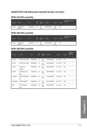
...; 16-18-18-36 1.35V •• 16-18-18-36 1.35V •• 16-16-16-39 1.35V 15-15-15-35 1.35V Chapter 1 ASUS SABERTOOTH X99 1-13 Size SS/ DS Chip Brand Chip NO. G.SKILL F4-3333C16Q- 16GRK DIMM socket support Size SS/ DS Chip Brand Chip NO. G.SKILL F4-3300C16Q... Brand Chip NO. (Optional) Timing Voltage 2 4 8 16GB(4GB*4) SS SK hynix H5AN4G8NMFR 16-1616-36 1.35V • • DDR4 3200 MHz capability Vendors Part No. SABERTOOTH X99 Motherboard Qualified Vendors Lists (QVL) DDR4 3333 MHz capability Vendors Part No.
...; 16-18-18-36 1.35V •• 16-18-18-36 1.35V •• 16-16-16-39 1.35V 15-15-15-35 1.35V Chapter 1 ASUS SABERTOOTH X99 1-13 Size SS/ DS Chip Brand Chip NO. G.SKILL F4-3333C16Q- 16GRK DIMM socket support Size SS/ DS Chip Brand Chip NO. G.SKILL F4-3300C16Q... Brand Chip NO. (Optional) Timing Voltage 2 4 8 16GB(4GB*4) SS SK hynix H5AN4G8NMFR 16-1616-36 1.35V • • DDR4 3200 MHz capability Vendors Part No. SABERTOOTH X99 Motherboard Qualified Vendors Lists (QVL) DDR4 3333 MHz capability Vendors Part No.
User Guide
Page 33
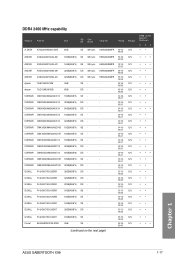
... on the next page) 15-15- 1.2V 15-35 16-16- 1.2V 16-40 DIMM socket support (Optional) 2 48 •• ••• Chapter 1 ASUS SABERTOOTH X99 1-17 Size SS/ Chip DS Brand Chip NO. DDR4 2400 MHz capability Vendors Part No.
... on the next page) 15-15- 1.2V 15-35 16-16- 1.2V 16-40 DIMM socket support (Optional) 2 48 •• ••• Chapter 1 ASUS SABERTOOTH X99 1-17 Size SS/ Chip DS Brand Chip NO. DDR4 2400 MHz capability Vendors Part No.

User Guide
Page 37
...you install the modules into slots B1 and D1 for better compatibility. settings in the BIOS for the hyper DIMM support. • Visit the ASUS website for better compatibility. • Side(s): SS - We suggest that you install the modules into slots A1, B1, B2, C1, D1,...provides hyper DIMM support function. • Hyper DIMM support is subject to the physical characteristics of quad-channel memory configuration. Chapter 1 ASUS SABERTOOTH X99 1-21 Supports eight (8) modules inserted into slots A1, B1, C1, and D1 for better compatibility. We suggest that you install ...
...you install the modules into slots B1 and D1 for better compatibility. settings in the BIOS for the hyper DIMM support. • Visit the ASUS website for better compatibility. • Side(s): SS - We suggest that you install the modules into slots A1, B1, B2, C1, D1,...provides hyper DIMM support function. • Hyper DIMM support is subject to the physical characteristics of quad-channel memory configuration. Chapter 1 ASUS SABERTOOTH X99 1-21 Supports eight (8) modules inserted into slots A1, B1, C1, and D1 for better compatibility. We suggest that you install ...
User Guide
Page 39
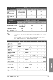
shared - - - - Chapter 1 ASUS SABERTOOTH X99 1-23 shared - 40-LANE CPU VGA configuration Single VGA/PCIe card Dual VGA/PCIe cards Triple VGA/PCIe cards PCI Express 3.0 operating mode PCIe 3.0/2.0 x16_1 ...
shared - - - - Chapter 1 ASUS SABERTOOTH X99 1-23 shared - 40-LANE CPU VGA configuration Single VGA/PCIe card Dual VGA/PCIe cards Triple VGA/PCIe cards PCI Express 3.0 operating mode PCIe 3.0/2.0 x16_1 ...
User Guide
Page 41
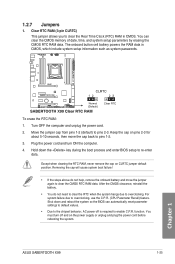
... the onboard battery and move the cap back to enable C.P.R. Move the jumper cap from pins 1-2 (default) to overclocking, use the C.P.R. (CPU Parameter Recall) feature. ASUS SABERTOOTH X99 1-25 Chapter 1 Shut down the key during the boot process and enter BIOS setup to clear the Real Time Clock (RTC) RAM in CMOS, which...
... the onboard battery and move the cap back to enable C.P.R. Move the jumper cap from pins 1-2 (default) to overclocking, use the C.P.R. (CPU Parameter Recall) feature. ASUS SABERTOOTH X99 1-25 Chapter 1 Shut down the key during the boot process and enter BIOS setup to clear the Real Time Clock (RTC) RAM in CMOS, which...

User Guide
Page 43
If an error is found, the critical component's LED stays lit up until the problem is solved. POST State LEDs The POST State LEDs provide the status of these key components during POST (Power-On-Self Test): CPU, memory modules, VGA card, and hard disk drives. Chapter 1 ASUS SABERTOOTH X99 1-27 1.2.8 Onboard LEDs 1.
If an error is found, the critical component's LED stays lit up until the problem is solved. POST State LEDs The POST State LEDs provide the status of these key components during POST (Power-On-Self Test): CPU, memory modules, VGA card, and hard disk drives. Chapter 1 ASUS SABERTOOTH X99 1-27 1.2.8 Onboard LEDs 1.
User Guide
Page 45
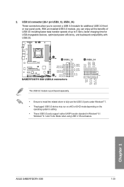
... the benefits of USB 3.0 including faster data transfer speeds of up to 5 Gb/s, faster charging time for additional USB 3.0 front or rear panel ports. Chapter 1 ASUS SABERTOOTH X99 1-29 The USB 3.0 module is purchased separately. • Ensure to install the related driver to connect a USB 3.0 module for USB-chargeable devices, optimized power efficiency...
... the benefits of USB 3.0 including faster data transfer speeds of up to 5 Gb/s, faster charging time for additional USB 3.0 front or rear panel ports. Chapter 1 ASUS SABERTOOTH X99 1-29 The USB 3.0 module is purchased separately. • Ensure to install the related driver to connect a USB 3.0 module for USB-chargeable devices, optimized power efficiency...

User Guide
Page 47
Chapter 1 ASUS SABERTOOTH X99 1-31 Connect the USB module cable to any of these connectors, then install the module to the USB connector onboard if your chassis supports front panel USB ports. You can connect the front panel USB cable to the ASUS Q-Connector (USB, dark brown) first, and then install the Q-Connector (USB) to...
Chapter 1 ASUS SABERTOOTH X99 1-31 Connect the USB module cable to any of these connectors, then install the module to the USB connector onboard if your chassis supports front panel USB ports. You can connect the front panel USB cable to the ASUS Q-Connector (USB, dark brown) first, and then install the Q-Connector (USB) to...

User Guide
Page 49
... panel audio module to this connector, set the Front Panel Type item in the BIOS setup to detect its temperature. Thermal Sensor connectors (2-pin T_SENSOR1; ASUS SABERTOOTH X99 1-33 Chapter 1 T_SENSOR2;T_SENSOR3) These connectors are for a chassis-mounted front panel audio I /O module cable to this connector. • We recommend that you want to...
... panel audio module to this connector, set the Front Panel Type item in the BIOS setup to detect its temperature. Thermal Sensor connectors (2-pin T_SENSOR1; ASUS SABERTOOTH X99 1-33 Chapter 1 T_SENSOR2;T_SENSOR3) These connectors are for a chassis-mounted front panel audio I /O module cable to this connector. • We recommend that you want to...

User Guide
Page 51
... connector is for the chassis-mounted reset button for the chassis-mounted system warning speaker. The IDE LED lights up when you to this connector. ASUS SABERTOOTH X99 1-35 Chapter 1 Pressing the power switch for more than four seconds while the system is ON turns the system OFF. • Reset button (2-pin RESET...
... connector is for the chassis-mounted reset button for the chassis-mounted system warning speaker. The IDE LED lights up when you to this connector. ASUS SABERTOOTH X99 1-35 Chapter 1 Pressing the power switch for more than four seconds while the system is ON turns the system OFF. • Reset button (2-pin RESET...

User Guide
Page 53
... an M.2 (NGFF) SSD module. • This socket supports M Key and type 2242/2260/2280 storage devices. • The M.2 Socket 3 shares bandwidth with PCIe x16_3 slot. ASUS SABERTOOTH X99 1-37 Chapter 1 The add-on Thunderbolt I /O card and Thunderbolt cables are purchased separately. 13. The M.2 (NGFF) SSD module is for more details. Thunderbolt header (5-pin...
... an M.2 (NGFF) SSD module. • This socket supports M Key and type 2242/2260/2280 storage devices. • The M.2 Socket 3 shares bandwidth with PCIe x16_3 slot. ASUS SABERTOOTH X99 1-37 Chapter 1 The add-on Thunderbolt I /O card and Thunderbolt cables are purchased separately. 13. The M.2 (NGFF) SSD module is for more details. Thunderbolt header (5-pin...

User Guide
Page 55
Place the motherboard into the chassis, ensuring that its rear I/O ports are the same for reference only. The motherboard layout may vary with models, but the installation steps are aligned to the chassis rear I /O panel. Chapter 2 ASUS SABERTOOTH X99 2-1 Install the ASUS Q-Shield to the chassis' rear I /O panel. 2. Chapter 2: Basic installation Basic installation 2.1 Building your PC system 2 2.1.1 Motherboard installation The diagrams in this section are for all models. 1.
Place the motherboard into the chassis, ensuring that its rear I/O ports are the same for reference only. The motherboard layout may vary with models, but the installation steps are aligned to the chassis rear I /O panel. Chapter 2 ASUS SABERTOOTH X99 2-1 Install the ASUS Q-Shield to the chassis' rear I /O panel. 2. Chapter 2: Basic installation Basic installation 2.1 Building your PC system 2 2.1.1 Motherboard installation The diagrams in this section are for all models. 1.

User Guide
Page 57
2.1.2 CPU installation Please note the order in this manual. C A B A B Triangle mark B A Triangle mark Chapter 2 ASUS SABERTOOTH X99 2-3 Follow the instructions printed on the metal sealing hatch or the illustrations shown below in opening/ closing the double latch. The plastic cap will pop up automatically once the CPU is in place and the hatch properly sealed down.
2.1.2 CPU installation Please note the order in this manual. C A B A B Triangle mark B A Triangle mark Chapter 2 ASUS SABERTOOTH X99 2-3 Follow the instructions printed on the metal sealing hatch or the illustrations shown below in opening/ closing the double latch. The plastic cap will pop up automatically once the CPU is in place and the hatch properly sealed down.


