User Guide
Page 2
... Computer Inc. Offer to the email address gpl@asus.com, stating the product and describing the problem (please DO NOT send large attachments such as the corresponding binary/object code. SPECIFICATIONS AND INFORMATION CONTAINED IN THIS MANUAL ARE FURNISHED FOR INFORMATIONAL USE ONLY, AND ARE SUBJECT TO CHANGE AT ANY TIME WITHOUT NOTICE, AND SHOULD NOT BE...
... Computer Inc. Offer to the email address gpl@asus.com, stating the product and describing the problem (please DO NOT send large attachments such as the corresponding binary/object code. SPECIFICATIONS AND INFORMATION CONTAINED IN THIS MANUAL ARE FURNISHED FOR INFORMATIONAL USE ONLY, AND ARE SUBJECT TO CHANGE AT ANY TIME WITHOUT NOTICE, AND SHOULD NOT BE...
User Guide
Page 5
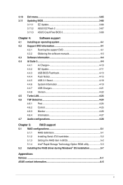
...Information 4-19 4.4.7 USB Charger 4-21 4.4.8 Version 4-22 4.5 Turbo LAN 4-23 4.6 TUF Detective 4-24 4.6.1 Post 4-24 4.6.2 Control 4-25 4.6.3 Monitor 4-26 4.6.4 Information 4-27 4.7 Audio configurations 4-28 Chapter 5: RAID support 5.1 RAID configurations 5-1 5.1.1 RAID definitions 5-1 5.1.2 Installing Serial ATA hard disks 5-2 5.1.3 Setting the RAID item in BIOS 5-2 5.1.4 Intel® Rapid Storage Technology Option ROM utility 5-3 5.2 Installing the RAID driver during Windows® OS installation 5-7 Appendices Notices ...A-1 ASUS contact information A-5 v
...Information 4-19 4.4.7 USB Charger 4-21 4.4.8 Version 4-22 4.5 Turbo LAN 4-23 4.6 TUF Detective 4-24 4.6.1 Post 4-24 4.6.2 Control 4-25 4.6.3 Monitor 4-26 4.6.4 Information 4-27 4.7 Audio configurations 4-28 Chapter 5: RAID support 5.1 RAID configurations 5-1 5.1.1 RAID definitions 5-1 5.1.2 Installing Serial ATA hard disks 5-2 5.1.3 Setting the RAID item in BIOS 5-2 5.1.4 Intel® Rapid Storage Technology Option ROM utility 5-3 5.2 Installing the RAID driver during Windows® OS installation 5-7 Appendices Notices ...A-1 ASUS contact information A-5 v

User Guide
Page 10
...® Core™ i7 Processors - 1 x M.2 x4 Socket 3 with M Key, type 2242/2260/2280/22110 storage devices support (Support PCIE SSD only) Intel® X99 Express Chipset with RAID 0, 1, 5, 10 and Intel Rapid Storage Technology 13 support - 1 x SATA Express Port (gray, compatible with 2 x SATA 6.0 Gb/s ports) - 8 x SATA 6.0 Gb/s ports* (4 x beige/gray from controller 1, 4 x black from controller 2) - Audio Amplifier to chipset behavior, the SATA6G_78, SATA6G_910 ports (black) do not support IRST including RAID ** These functions will work depending on the next page) x High Quality 112dB...
...® Core™ i7 Processors - 1 x M.2 x4 Socket 3 with M Key, type 2242/2260/2280/22110 storage devices support (Support PCIE SSD only) Intel® X99 Express Chipset with RAID 0, 1, 5, 10 and Intel Rapid Storage Technology 13 support - 1 x SATA Express Port (gray, compatible with 2 x SATA 6.0 Gb/s ports) - 8 x SATA 6.0 Gb/s ports* (4 x beige/gray from controller 1, 4 x black from controller 2) - Audio Amplifier to chipset behavior, the SATA6G_78, SATA6G_910 ports (black) do not support IRST including RAID ** These functions will work depending on the next page) x High Quality 112dB...
User Guide
Page 12
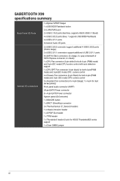
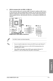
SABERTOOTH X99 specifications summary Back Panel I/O Ports Internal I/O connectors 1 x Optical S/PDIF Output 1 x USB BIOS Flashback button 2 x LAN (RJ45) port 2 x USB 3.1/3.0 ports (teal blue, supports ASUS USB 3.1 Boost) 4 x USB 3.0/2.0 ports (blue, 1 supports USB BIOS Flashback) 4 x USB 2.0/1.1 ports 8-channel Audio I/O ports 2 x USB 3.0/2.0 connector support additional 4 USB 3.0/2.0 ports (19-bin; button 1 x DRCT (DirectKey) connector 3 x Thermal Sensor (T_Sensor) headers 1 x chassis intrusion header 1 x S/PDIF Out header 1 x TPM header 1 x Thunderbolt header (5-pin) for dust de-fan [...
SABERTOOTH X99 specifications summary Back Panel I/O Ports Internal I/O connectors 1 x Optical S/PDIF Output 1 x USB BIOS Flashback button 2 x LAN (RJ45) port 2 x USB 3.1/3.0 ports (teal blue, supports ASUS USB 3.1 Boost) 4 x USB 3.0/2.0 ports (blue, 1 supports USB BIOS Flashback) 4 x USB 2.0/1.1 ports 8-channel Audio I/O ports 2 x USB 3.0/2.0 connector support additional 4 USB 3.0/2.0 ports (19-bin; button 1 x DRCT (DirectKey) connector 3 x Thermal Sensor (T_Sensor) headers 1 x chassis intrusion header 1 x S/PDIF Out header 1 x TPM header 1 x Thunderbolt header (5-pin) for dust de-fan [...
User Guide
Page 14
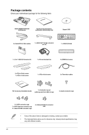
... the following items User Manual ASUS SABERTOOTH X99 motherboard Technical documentations, certification and warranty card Support DVD 6 x Serial ATA 6.0 Gb/s cables 1 x ASUS SLI™ bridge connector (12 cm) 1 x ASUS Q-Shield 1 x 2-in-1 ASUS Q-Connector kit 1 x 40 mm Assistant fan 4 x DRAM slot covers 2 x PCIe x16 slot covers 1 x PCIe x1 slot covers 1 x PCIe x4 slot covers 3 x Thermistor cables TUF Accessory Installation Guide 1 x Connector cap set (LAN cap and Front USB 3.0 cap) 5 x Audio connector caps ExSprAeTssA 9 x SATA connector caps 1 x SATA Expresss connector cap 11...
... the following items User Manual ASUS SABERTOOTH X99 motherboard Technical documentations, certification and warranty card Support DVD 6 x Serial ATA 6.0 Gb/s cables 1 x ASUS SLI™ bridge connector (12 cm) 1 x ASUS Q-Shield 1 x 2-in-1 ASUS Q-Connector kit 1 x 40 mm Assistant fan 4 x DRAM slot covers 2 x PCIe x16 slot covers 1 x PCIe x1 slot covers 1 x PCIe x4 slot covers 3 x Thermistor cables TUF Accessory Installation Guide 1 x Connector cap set (LAN cap and Front USB 3.0 cap) 5 x Audio connector caps ExSprAeTssA 9 x SATA connector caps 1 x SATA Expresss connector cap 11...
User Guide
Page 25
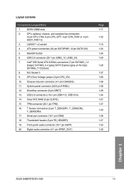
...Layout contents Connectors/Jumpers/Slots 1. Intel® X99 Serial ATA 6.0Gb/s connectors (7-pin SATA6G_1-2 [beige]; M.2 Socket 3 9. Chassis intrusion connector (4-1 pin CHASSIS) 11. DirectKey connector (2-pin DRCT) 13. Serial port connector (10-1 pin COM) 18. LGA2011-v3 socket 4. USB 3.0 connector (20-1 pin USB3_12, USB3_34) 7. SATA6G_7-10 [black] 8. System panel connector (20-8 pin PANEL) 12. TPM connector (20-1 pin TPM) 16. CPU, optional, chassis, and assistant fan connectors (4-pin CPU_FAN; 4-pin CPU_OPT; 4-pin CHA_FAN1-4; 4-pin ASST_FAN1-5) 3. ATX power connectors...
...Layout contents Connectors/Jumpers/Slots 1. Intel® X99 Serial ATA 6.0Gb/s connectors (7-pin SATA6G_1-2 [beige]; M.2 Socket 3 9. Chassis intrusion connector (4-1 pin CHASSIS) 11. DirectKey connector (2-pin DRCT) 13. Serial port connector (10-1 pin COM) 18. LGA2011-v3 socket 4. USB 3.0 connector (20-1 pin USB3_12, USB3_34) 7. SATA6G_7-10 [black] 8. System panel connector (20-8 pin PANEL) 12. TPM connector (20-1 pin TPM) 16. CPU, optional, chassis, and assistant fan connectors (4-pin CPU_FAN; 4-pin CPU_OPT; 4-pin CHA_FAN1-4; 4-pin ASST_FAN1-5) 3. ATX power connectors...
User Guide
Page 41
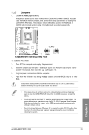
... the BIOS can clear the CMOS memory of date, time, and system setup parameters by erasing the CMOS RTC RAM data. For system failure due to overclocking. 1.2.7 Jumpers 1. Plug the power cord and turn off is required to pins 1-2. 3. After the CMOS clearance, reinstall the battery. • You do not help, remove the onboard battery and move the cap back to enable C.P.R. You must turn ON the computer. 4. The onboard button cell battery powers the RAM...
... the BIOS can clear the CMOS memory of date, time, and system setup parameters by erasing the CMOS RTC RAM data. For system failure due to overclocking. 1.2.7 Jumpers 1. Plug the power cord and turn off is required to pins 1-2. 3. After the CMOS clearance, reinstall the battery. • You do not help, remove the onboard battery and move the cap back to enable C.P.R. You must turn ON the computer. 4. The onboard button cell battery powers the RAM...
User Guide
Page 45
... USB 3.0 ports under Windows® 7. • Theplugged USB 3.0 device may run on xHCi or EHCl mode depending on the operating system's setting. • These USB 3.0 ports support native UASP transfer standard in Windows® 8 / Windows® 8.1 and Turbo Mode when using USB 3.1 Boost feature. The USB 3.0 module is purchased separately. • Ensure to install the related driver to 5 Gb/s, faster charging time for additional USB 3.0 front or rear panel ports. Chapter 1 ASUS SABERTOOTH X99...
... USB 3.0 ports under Windows® 7. • Theplugged USB 3.0 device may run on xHCi or EHCl mode depending on the operating system's setting. • These USB 3.0 ports support native UASP transfer standard in Windows® 8 / Windows® 8.1 and Turbo Mode when using USB 3.1 Boost feature. The USB 3.0 module is purchased separately. • Ensure to install the related driver to 5 Gb/s, faster charging time for additional USB 3.0 front or rear panel ports. Chapter 1 ASUS SABERTOOTH X99...

User Guide
Page 73
... default screen for the advanced BIOS settings. Click the button to manually tune the fans Shows the bootable devices Saves the changes and resets the system Loads optimized default settings Displays the Advanced mode menus Selects the boot device priority The boot device options vary depending on the devices you installed to the Setup Mode item in section 3.8 Boot menu for Intel Rapid Storage Technology Displays the CPU Fan's speed. ASUS SABERTOOTH X99 3-3 Refer to the system. Displays the CPU/motherboard temperature, CPU voltage output, CPU/chassis/power fan speed, and SATA...
... default screen for the advanced BIOS settings. Click the button to manually tune the fans Shows the bootable devices Saves the changes and resets the system Loads optimized default settings Displays the Advanced mode menus Selects the boot device priority The boot device options vary depending on the devices you installed to the Setup Mode item in section 3.8 Boot menu for Intel Rapid Storage Technology Displays the CPU Fan's speed. ASUS SABERTOOTH X99 3-3 Refer to the system. Displays the CPU/motherboard temperature, CPU voltage output, CPU/chassis/power fan speed, and SATA...
User Guide
Page 95
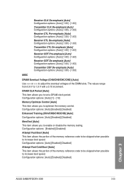
...options: [Auto] [Enabled] [Disabled] Chapter 3 ASUS SABERTOOTH X99 3-25 Configuration options: [Auto] [Enabled] [Disabled] Attempt Fast Cold Boot [Auto] This item allows the portion of the memory reference code to be skipped when possible to increase boot speed. Configuration options: [Enabled] [Disabled] Attempt Fast Boot [Auto] This item allows the portion of the DIMM slots. Configuration options: [Auto] [Enabled] [Disabled] Enhanced Training (CHA/CHB/CHC/CHD) [Auto] Configuration options: [Auto] [Enabled] [Disabled] MemTest [Auto] This item allows you to optimize the memory control...
...options: [Auto] [Enabled] [Disabled] Chapter 3 ASUS SABERTOOTH X99 3-25 Configuration options: [Auto] [Enabled] [Disabled] Attempt Fast Cold Boot [Auto] This item allows the portion of the memory reference code to be skipped when possible to increase boot speed. Configuration options: [Enabled] [Disabled] Attempt Fast Boot [Auto] This item allows the portion of the DIMM slots. Configuration options: [Auto] [Enabled] [Disabled] Enhanced Training (CHA/CHB/CHC/CHD) [Auto] Configuration options: [Auto] [Enabled] [Disabled] MemTest [Auto] This item allows you to optimize the memory control...
User Guide
Page 110
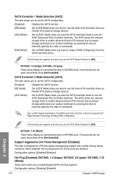
...onboard storage driver to enable advanced Serial ATA features that increases storage performance on random workloads by allowing the drive to internally optimize the order of SATA ports are not used , these items show [Not Installed]. SATA Controller 2 Mode Selection [AHCI] This item allows you to set the SATA Mode Selection to create a RAID configuration from controller 2 does not support Intel® Rapid Storage Technology including RAID configuration. SATA6G_7-10 (Black) These items display all connected devices to enable/disable SATA Hot Plug Support. Configuration options...
...onboard storage driver to enable advanced Serial ATA features that increases storage performance on random workloads by allowing the drive to internally optimize the order of SATA ports are not used , these items show [Not Installed]. SATA Controller 2 Mode Selection [AHCI] This item allows you to set the SATA Mode Selection to create a RAID configuration from controller 2 does not support Intel® Rapid Storage Technology including RAID configuration. SATA6G_7-10 (Black) These items display all connected devices to enable/disable SATA Hot Plug Support. Configuration options...
User Guide
Page 118
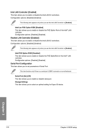
... a motherboard. Configuration options: [Disabled] [Enabled] The following item appears only when you set the Intel LAN Controller to enable or disable the PXE OptionRom of the Intel® LAN controller. Chapter 3 3-48 Chapter 3: BIOS setup Serial Port [On] [Off] This item allows you to select an optimal setting for Super IO device. Configuration options: [Enabled] [Disabled] Serial Port Configuration This item allows you to [Enabled]. Change Settings This item allows you to enable or disable the Intel LAN1/2 controllers. Intel Lan PXE Option ROM [Disabled...
... a motherboard. Configuration options: [Disabled] [Enabled] The following item appears only when you set the Intel LAN Controller to enable or disable the PXE OptionRom of the Intel® LAN controller. Chapter 3 3-48 Chapter 3: BIOS setup Serial Port [On] [Off] This item allows you to select an optimal setting for Super IO device. Configuration options: [Enabled] [Disabled] Serial Port Configuration This item allows you to [Enabled]. Change Settings This item allows you to enable or disable the Intel LAN1/2 controllers. Intel Lan PXE Option ROM [Disabled...
User Guide
Page 127
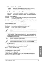
... the BIOS Setup directly when you press the DirectKey button. [Enabled] Allows the system to power on state of the chassis reset button cable to the onboard DRCT header. You can only execute the POST delay time during POST. Network Stack Driver Support [Disabled] [Disabled] Select to skip the network stack driver from 0 to 10 seconds. Connect the 2-pin connector of the NumLock. This feature only works when set the Boot Logo Display to [Auto] and [Full Screen]. The...
... the BIOS Setup directly when you press the DirectKey button. [Enabled] Allows the system to power on state of the chassis reset button cable to the onboard DRCT header. You can only execute the POST delay time during POST. Network Stack Driver Support [Disabled] [Disabled] Select to skip the network stack driver from 0 to 10 seconds. Connect the 2-pin connector of the NumLock. This feature only works when set the Boot Logo Display to [Auto] and [Full Screen]. The...
User Guide
Page 132
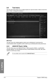
... 3.11.2 ASUS EZ Flash 2. 3-62 Chapter 3: BIOS setup Chapter 3 For more details, refer to display the submenu. When you to confirm your motherboard. GPU Post This item shows the installed graphics cards in your choice. It slao shows the recommended number of graphics card to install to configure options for best performance. 3.9.1 ASUS EZ Flash 2 Utility This item allows you press , a confirmation message appears. 3.9 Tool menu The Tool menu items...
... 3.11.2 ASUS EZ Flash 2. 3-62 Chapter 3: BIOS setup Chapter 3 For more details, refer to display the submenu. When you to confirm your motherboard. GPU Post This item shows the installed graphics cards in your choice. It slao shows the recommended number of graphics card to install to configure options for best performance. 3.9.1 ASUS EZ Flash 2 Utility This item allows you press , a confirmation message appears. 3.9 Tool menu The Tool menu items...
User Guide
Page 136
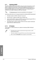
... your BIOS when necessary. However, BIOS updating is no problem using a USB flash drive. 3. ASUS BIOS Updater: Updates the BIOS in Windows® environment. 2. 3.11 Updating BIOS The ASUS website publishes the latest BIOS versions to boot. EZ Update: Updates the BIOS in DOS environment using the motherboard support DVD or a USB flash drive when the BIOS file fails or gets corrupted. 4. The following utilities allow you to update the motherboard BIOS in Windows® environment. • EZ Update requires an Internet connection either through a network or an ISP (Internet Service...
... your BIOS when necessary. However, BIOS updating is no problem using a USB flash drive. 3. ASUS BIOS Updater: Updates the BIOS in Windows® environment. 2. 3.11 Updating BIOS The ASUS website publishes the latest BIOS versions to boot. EZ Update: Updates the BIOS in DOS environment using the motherboard support DVD or a USB flash drive when the BIOS file fails or gets corrupted. 4. The following utilities allow you to update the motherboard BIOS in Windows® environment. • EZ Update requires an Internet connection either through a network or an ISP (Internet Service...
User Guide
Page 138
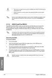
... updating the BIOS! You can cause system boot failure! Recovering the BIOS To recover the BIOS: 1. When found, the utility reads the BIOS file and enters ASUS EZ Flash 2 automatically. 4. Select the Load Optimized Defaults item under the Exit menu. Ensure to load the BIOS default settings to prevent system boot failure! If you to a USB flash drive. See section 3.10 Exit Menu for the BIOS file. Chapter 3 3-68 Chapter 3: BIOS setup Doing so can restore a corrupted BIOS file using the motherboard support DVD or a USB flash drive...
... updating the BIOS! You can cause system boot failure! Recovering the BIOS To recover the BIOS: 1. When found, the utility reads the BIOS file and enters ASUS EZ Flash 2 automatically. 4. Select the Load Optimized Defaults item under the Exit menu. Ensure to load the BIOS default settings to prevent system boot failure! If you to a USB flash drive. See section 3.10 Exit Menu for the BIOS file. Chapter 3 3-68 Chapter 3: BIOS setup Doing so can restore a corrupted BIOS file using the motherboard support DVD or a USB flash drive...
User Guide
Page 139
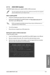
... http://support.asus.com and save them in DOS: 1. Boot your USB flash drive. Booting the system in DOS environment To boot the system in your computer then press to the USB port. 2. Please select boot device: E1: ASUS DVD-E818A6T (4069MB) USB DISK 2.0 (3824MB) UEFI: (FAT) USB DISK 2.0 (3824MB) Enter Setup and to move selection ENTER to select boot device ESC to update the BIOS in DOS environment. 3.11.4 ASUS BIOS Updater ASUS BIOS Updater allows you to boot using defaults Chapter 3 ASUS SABERTOOTH X99...
... http://support.asus.com and save them in DOS: 1. Boot your USB flash drive. Booting the system in DOS environment To boot the system in your computer then press to the USB port. 2. Please select boot device: E1: ASUS DVD-E818A6T (4069MB) USB DISK 2.0 (3824MB) UEFI: (FAT) USB DISK 2.0 (3824MB) Enter Setup and to move selection ENTER to select boot device ESC to update the BIOS in DOS environment. 3.11.4 ASUS BIOS Updater ASUS BIOS Updater allows you to boot using defaults Chapter 3 ASUS SABERTOOTH X99...
User Guide
Page 144
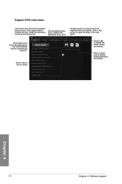
... Utilities menu shows the applications and other software that the motherboard supports. Click or tap an item to install Click or tap to display DVD/motherboard information Chapter 4 4-2 Chapter 4: Software support Click or tap an item to use the devices. Click or tap an icon to display the ASUS contact information. The Manual menu contains the list of the user guide. Install the necessary drivers to open the folder of supplementary user guides. The AHCI/RAID Driver menu...
... Utilities menu shows the applications and other software that the motherboard supports. Click or tap an item to install Click or tap to display DVD/motherboard information Chapter 4 4-2 Chapter 4: Software support Click or tap an item to use the devices. Click or tap an icon to display the ASUS contact information. The Manual menu contains the list of the user guide. Install the necessary drivers to open the folder of supplementary user guides. The AHCI/RAID Driver menu...
User Guide
Page 174
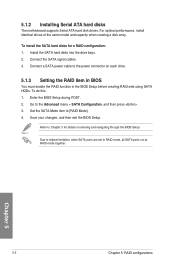
... power connector on entering and navigating through the BIOS Setup Due to chipset limitation, when SATA ports are set to [RAID Mode]. 4. Refer to Chapter 3 for a RAID configuration: 1. Connect the SATA signal cables. 3. Chapter 5 5-2 Chapter 5: RAID configurations Enter the BIOS Setup during POST. 2. Save your changes, and then exit the BIOS Setup. Install the SATA hard disks into the drive bays. 2. Set the SATA Mode item to RAID mode, all SATA ports run at RAID mode together. 5.1.2 Installing Serial ATA hard disks The motherboard supports Serial ATA hard disk drives...
... power connector on entering and navigating through the BIOS Setup Due to chipset limitation, when SATA ports are set to [RAID Mode]. 4. Refer to Chapter 3 for a RAID configuration: 1. Connect the SATA signal cables. 3. Chapter 5 5-2 Chapter 5: RAID configurations Enter the BIOS Setup during POST. 2. Save your changes, and then exit the BIOS Setup. Install the SATA hard disks into the drive bays. 2. Set the SATA Mode item to RAID mode, all SATA ports run at RAID mode together. 5.1.2 Installing Serial ATA hard disks The motherboard supports Serial ATA hard disk drives...
User Guide
Page 179
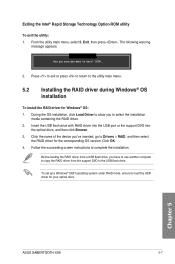
... USB flash drive with RAID driver into the USB port or the support DVD into the optical drive, and then click Browse. 3. From the utility main menu, select 5. Exiting the Intel® Rapid Storage Technology Option ROM utility To exit the utility: 1. Follow the succeeding screen instructions to select the installation media containing the RAID driver. 2. During the OS installation, click Load Driver to allow you have to use another computer to copy the RAID driver from the support DVD to load the UEFI driver...
... USB flash drive with RAID driver into the USB port or the support DVD into the optical drive, and then click Browse. 3. From the utility main menu, select 5. Exiting the Intel® Rapid Storage Technology Option ROM utility To exit the utility: 1. Follow the succeeding screen instructions to select the installation media containing the RAID driver. 2. During the OS installation, click Load Driver to allow you have to use another computer to copy the RAID driver from the support DVD to load the UEFI driver...


