User Manual
Page 2
... address). SPECIFICATIONS AND INFORMATION CONTAINED IN THIS MANUAL ARE FURNISHED FOR INFORMATIONAL USE ONLY, AND ARE SUBJECT TO CHANGE AT ANY TIME WITHOUT NOTICE, AND SHOULD NOT BE CONSTRUED AS A COMMITMENT BY ASUS. Products and corporate names appearing in writing by downloading it from http://support.asus.com/download; You may not be extended if: (1) the product is repaired, modified...
... address). SPECIFICATIONS AND INFORMATION CONTAINED IN THIS MANUAL ARE FURNISHED FOR INFORMATIONAL USE ONLY, AND ARE SUBJECT TO CHANGE AT ANY TIME WITHOUT NOTICE, AND SHOULD NOT BE CONSTRUED AS A COMMITMENT BY ASUS. Products and corporate names appearing in writing by downloading it from http://support.asus.com/download; You may not be extended if: (1) the product is repaired, modified...
User Manual
Page 5
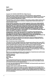
... Setting the RAID item in BIOS 4-30 4.4.4 AMD® Option ROM Utility 4-31 4.5 Creating a RAID driver disk 4-34 4.5.1 Creating a RAID driver disk without entering the OS 4-34 4.5.2 Creating a RAID driver disk in Windows 4-34 4.5.3 Installing the RAID driver during Windows® OS installation....... 4-35 4.5.4 Using a USB floppy disk drive 4-36 Chapter 5: Multiple GPU technology support 5.1 ATI® CrossFireX™ technology 5-1 5.1.1 Requirements 5-1 5.1.2 Before you begin 5-1 5.1.3 Installing two CrossFireX™ graphics cards 5-2 5.1.4 Installing the device drivers...
... Setting the RAID item in BIOS 4-30 4.4.4 AMD® Option ROM Utility 4-31 4.5 Creating a RAID driver disk 4-34 4.5.1 Creating a RAID driver disk without entering the OS 4-34 4.5.2 Creating a RAID driver disk in Windows 4-34 4.5.3 Installing the RAID driver during Windows® OS installation....... 4-35 4.5.4 Using a USB floppy disk drive 4-36 Chapter 5: Multiple GPU technology support 5.1 ATI® CrossFireX™ technology 5-1 5.1.1 Requirements 5-1 5.1.2 Before you begin 5-1 5.1.3 Installing two CrossFireX™ graphics cards 5-2 5.1.4 Installing the device drivers...
User Manual
Page 11
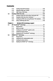
... "Safe & Stable!" Anti Surge Front Panel USB 3.0 Support ASUS UEFI BIOS EZ Mode featuring friendly graphics user interface AI Suite II ASUS Q-Connector ASUS Q-Shield ASUS Q-LED (CPU, DRAM, VGA, Boot Device LED) ASUS Q-Slot ASUS Q-DIMM ASUS O.C. TUF Thermal Radar "TUF ENGINE!" ESD Guards - certified by military-standard) - SABERTOOTH 990FX specifications summary USB Exclusive TUF Features Other Special Features BIOS Features 2 x ASMedia® USB 3.0 controllers - 2 x USB 3.0 ports at mid-board for front panel support - 2 x USB 3.0 ports at back panel (blue) AMD® SB950 chipset...
... "Safe & Stable!" Anti Surge Front Panel USB 3.0 Support ASUS UEFI BIOS EZ Mode featuring friendly graphics user interface AI Suite II ASUS Q-Connector ASUS Q-Shield ASUS Q-LED (CPU, DRAM, VGA, Boot Device LED) ASUS Q-Slot ASUS Q-DIMM ASUS O.C. TUF Thermal Radar "TUF ENGINE!" ESD Guards - certified by military-standard) - SABERTOOTH 990FX specifications summary USB Exclusive TUF Features Other Special Features BIOS Features 2 x ASMedia® USB 3.0 controllers - 2 x USB 3.0 ports at mid-board for front panel support - 2 x USB 3.0 ports at back panel (blue) AMD® SB950 chipset...
User Manual
Page 17
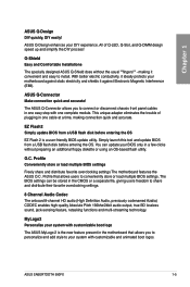
... or load multiple BIOS settings. ASUS Q-Connector Make connection quick and accurate! Simply launch this tool and update BIOS from a USB flash disk before entering the OS. ASUS SABERTOOTH 990FX 1-5 ASUS Q-Design enhances your BIOS only in one easy step with customizable boot logo The ASUS MyLogo 2 is a user-friendly BIOS update utility. making it ideally protects your system with one cable at a time, making connection quick and accurate. This unique adapter eliminates the trouble of Q-LED, Q-Slot...
... or load multiple BIOS settings. ASUS Q-Connector Make connection quick and accurate! Simply launch this tool and update BIOS from a USB flash disk before entering the OS. ASUS SABERTOOTH 990FX 1-5 ASUS Q-Design enhances your BIOS only in one easy step with customizable boot logo The ASUS MyLogo 2 is a user-friendly BIOS update utility. making it ideally protects your system with one cable at a time, making connection quick and accurate. This unique adapter eliminates the trouble of Q-LED, Q-Slot...
User Manual
Page 37
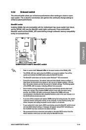
... this user manual or on the ASUS website at www.asus.com after using the MemOK! switch Installing DIMMs that you download and update to the latest BIOS version from the ASUS website at www.asus.com. • If you turn off the computer and replace DIMMs during POST reminding you to fine-tune performance when working on the computer. If the installed DIMMs still fail to boot and load BIOS default settings...
... this user manual or on the ASUS website at www.asus.com after using the MemOK! switch Installing DIMMs that you download and update to the latest BIOS version from the ASUS website at www.asus.com. • If you turn off the computer and replace DIMMs during POST reminding you to fine-tune performance when working on the computer. If the installed DIMMs still fail to boot and load BIOS default settings...
User Manual
Page 43
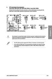
... motherboard components. Do not place jumper caps on the motherboard, ensuring that the black wire of each cable matches the ground pin of maximum 1A (12 W) fan power. • If you install two VGA cards, we recommend that you plug the rear chassis fan cable to the fan connectors. Chapter 2 ASUS SABERTOOTH 990FX 2-25 CHA_FAN1-3; 3-pin CHA_FAN4) Connect the fan cables to the fan connectors on the fan connectors! • The CPU_FAN connector supports the CPU fan of the connector. CPU and chassis fan connectors (4-pin CPU_FAN; CPU_OPT FAN...
... motherboard components. Do not place jumper caps on the motherboard, ensuring that the black wire of each cable matches the ground pin of maximum 1A (12 W) fan power. • If you install two VGA cards, we recommend that you plug the rear chassis fan cable to the fan connectors. Chapter 2 ASUS SABERTOOTH 990FX 2-25 CHA_FAN1-3; 3-pin CHA_FAN4) Connect the fan cables to the fan connectors on the fan connectors! • The CPU_FAN connector supports the CPU fan of the connector. CPU and chassis fan connectors (4-pin CPU_FAN; CPU_OPT FAN...
User Manual
Page 63
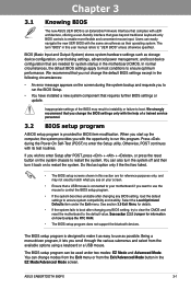
... enter the Setup utility. Select the Load Optimized Defaults item under two modes: EZ Mode and Advanced Mode. When you start up the computer, the system provides you change modes from the Exit menu or from the available options using a keyboard or a USB mouse. You can be used under the Exit menu. Otherwise, POST continues with uEFI architecture, offering a user-friendly interface that requires further BIOS settings or update. Chapter 3 Chapter 3: 3.1 Knowing BIOS BIOS setup The new ASUS UEFI BIOS...
... enter the Setup utility. Select the Load Optimized Defaults item under two modes: EZ Mode and Advanced Mode. When you start up the computer, the system provides you change modes from the Exit menu or from the available options using a keyboard or a USB mouse. You can be used under the Exit menu. Otherwise, POST continues with uEFI architecture, offering a user-friendly interface that requires further BIOS settings or update. Chapter 3 Chapter 3: 3.1 Knowing BIOS BIOS setup The new ASUS UEFI BIOS...
User Manual
Page 65
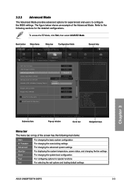
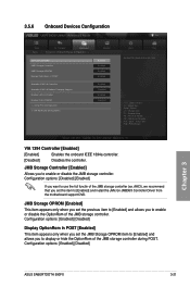
... the overclocking settings For changing the advanced system settings For displaying the system temperature, power status, and changing the fan settings. Advanced Mode General help Exit Main Back Ai Tweaker Advanced Advanced\ Onboard Devices Configuration > Monitor VIA 1394 Controller Enabled JMB Storage Controller Enabled JMB Storage OPROM Enabled Display OptionRom in POST Enabled JMB Storage OPROM Asmedia USB 3.0 Controller Enabled Asmedia USB 3.0 Battery Charging Support Disabled Enabled Realtek LAN Controller Enabled Realtek PXE OPROM Disabled > Serial Port...
... the overclocking settings For changing the advanced system settings For displaying the system temperature, power status, and changing the fan settings. Advanced Mode General help Exit Main Back Ai Tweaker Advanced Advanced\ Onboard Devices Configuration > Monitor VIA 1394 Controller Enabled JMB Storage Controller Enabled JMB Storage OPROM Enabled Display OptionRom in POST Enabled JMB Storage OPROM Asmedia USB 3.0 Controller Enabled Asmedia USB 3.0 Battery Charging Support Disabled Enabled Realtek LAN Controller Enabled Realtek PXE OPROM Disabled > Serial Port...
User Manual
Page 69
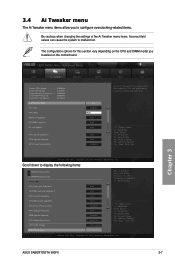
... enabled CPU Bus frequency, CPU ratio and memory parameters will be auto optimized. →←: Select Screen ↑↓: Select Item Enter: Select +/-: Change Opt. Copyright (C) 2010 American Megatrends, Inc. UEFI BIOS Utility - Probe Th... CPU & NB Voltage Offset Mode Offset Mode Sign + Min = 0.006250V Max = 0.793750V Standard = By CPU Oncrement = 0.006250V +/- : Raise/Reduce →←: Select Screen ↑↓: Select Item Enter: Select +/-: Change Opt. Chapter 3 ASUS SABERTOOTH 990FX 3-7 Scroll down to malfunction. The configuration options...
... enabled CPU Bus frequency, CPU ratio and memory parameters will be auto optimized. →←: Select Screen ↑↓: Select Item Enter: Select +/-: Change Opt. Copyright (C) 2010 American Megatrends, Inc. UEFI BIOS Utility - Probe Th... CPU & NB Voltage Offset Mode Offset Mode Sign + Min = 0.006250V Max = 0.793750V Standard = By CPU Oncrement = 0.006250V +/- : Raise/Reduce →←: Select Screen ↑↓: Select Item Enter: Select +/-: Change Opt. Chapter 3 ASUS SABERTOOTH 990FX 3-7 Scroll down to malfunction. The configuration options...
User Manual
Page 71
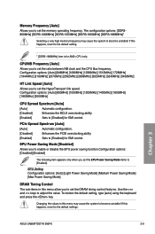
.... [Disabled] Enhances the PCIE overclocking ability [Enabled] Sets to [Enabled] for EMI control. To restore the default setting, type [auto] using the keyboard and press the key. Configuration options: [Auto] [800MHz] [1000MHz] [1200MHz] [1400MHz] [1600MHz] [1800MHz] [2000MHz] CPU Spread Spectrum [Auto] [Auto] Automatic configuration. [Disabled] Enhances the BCLK overclocking ability. [Enabled] Sets to [Enabled] for EMI control. EPU Setting Configuration options: [Auto] [Light Power Saving Mode] [Medium Power Saving Mode] [Max Power Saving Mode] DRAM Timing Control The...
.... [Disabled] Enhances the PCIE overclocking ability [Enabled] Sets to [Enabled] for EMI control. To restore the default setting, type [auto] using the keyboard and press the key. Configuration options: [Auto] [800MHz] [1000MHz] [1200MHz] [1400MHz] [1600MHz] [1800MHz] [2000MHz] CPU Spread Spectrum [Auto] [Auto] Automatic configuration. [Disabled] Enhances the BCLK overclocking ability. [Enabled] Sets to [Enabled] for EMI control. EPU Setting Configuration options: [Auto] [Light Power Saving Mode] [Medium Power Saving Mode] [Max Power Saving Mode] DRAM Timing Control The...
User Manual
Page 78
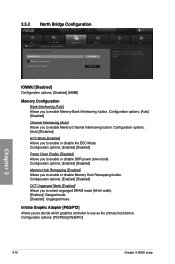
.... Configuration options: [Enabled] [Disabled] DCT Unganged Mode [Enabled] Allows you to enable Memory Bank Interleaving fuction. 3.5.2 North Bridge Configuration UEFI BIOS Utility - Configuration options: [Auto] [Disabled] Channel Interleaving [Auto] Allows you to use as the primary boot device. Configuration options: [Enabled] [Disabled] Power Down Enable [Disabled] Allows you to select unganged DRAM mode (64-bit width). [Enabled]: Ganged mode. [Disabled]: Unganged mose. Configuration options: [PCI/PEG] [PEG/PCI] Chapter 3 3-16 Chapter 3: BIOS setup Initiate Graphic Adapter...
.... Configuration options: [Enabled] [Disabled] DCT Unganged Mode [Enabled] Allows you to enable Memory Bank Interleaving fuction. 3.5.2 North Bridge Configuration UEFI BIOS Utility - Configuration options: [Auto] [Disabled] Channel Interleaving [Auto] Allows you to use as the primary boot device. Configuration options: [Enabled] [Disabled] Power Down Enable [Disabled] Allows you to select unganged DRAM mode (64-bit width). [Enabled]: Ganged mode. [Disabled]: Unganged mose. Configuration options: [PCI/PEG] [PEG/PCI] Chapter 3 3-16 Chapter 3: BIOS setup Initiate Graphic Adapter...
User Manual
Page 83
... Enabled Realtek PXE OPROM Disabled > Serial Port Configuration > SB HD Azalia Configuration Exit Boot Tool Enabled/Disabled Azalia VIA 1394 →←: Select Screen ↑↓: Select Item Enter: Select +/-: Change Opt. 3.5.6 Onboard Devices Configuration UEFI BIOS Utility - Copyright (C) 2010 American Megatrends, Inc. AHCI), we recommend that you set the JMB Storage OPROM item to [Enabled] and allows you want to display or hide the OptionRom of the JMB storage controller during POST. Configuration options: [Enabled] [Disabled] Chapter 3 ASUS SABERTOOTH 990FX...
... Enabled Realtek PXE OPROM Disabled > Serial Port Configuration > SB HD Azalia Configuration Exit Boot Tool Enabled/Disabled Azalia VIA 1394 →←: Select Screen ↑↓: Select Item Enter: Select +/-: Change Opt. 3.5.6 Onboard Devices Configuration UEFI BIOS Utility - Copyright (C) 2010 American Megatrends, Inc. AHCI), we recommend that you set the JMB Storage OPROM item to [Enabled] and allows you want to display or hide the OptionRom of the JMB storage controller during POST. Configuration options: [Enabled] [Disabled] Chapter 3 ASUS SABERTOOTH 990FX...
User Manual
Page 84
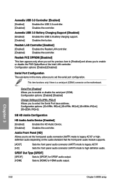
... 3: BIOS setup Configuration options: [Enabled] [Disabled] Serial Port Configuration The sub-items in this menu allow you to set the front panel audio connector (AAFP) mode to enable or disable the PXE OptionRom of the Intel LAN controller. Configuration options: [Enabled] [Disabled] Change Settings [IO=3F8h; IRQ=3] SB HD Azalia Configuration HD Audio Azalia Device [Enabled] [Enabled] Enables the HD Audio Device. [Disabled] Disables the controller. Azalia Front Panel [HD] Allows you to legacy AC'97 or highdefinition audio depending on the motherboard. Asmedia USB 3.0 Battery...
... 3: BIOS setup Configuration options: [Enabled] [Disabled] Serial Port Configuration The sub-items in this menu allow you to set the front panel audio connector (AAFP) mode to enable or disable the PXE OptionRom of the Intel LAN controller. Configuration options: [Enabled] [Disabled] Change Settings [IO=3F8h; IRQ=3] SB HD Azalia Configuration HD Audio Azalia Device [Enabled] [Enabled] Enables the HD Audio Device. [Disabled] Disables the controller. Azalia Front Panel [HD] Allows you to legacy AC'97 or highdefinition audio depending on the motherboard. Asmedia USB 3.0 Battery...
User Manual
Page 93
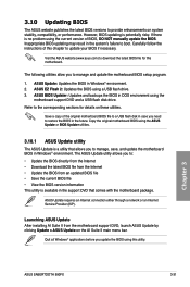
... utility is no problem using a USB flash drive. 3. Refer to boot. The following utilities allow you to : • Update the BIOS directly from the Internet • Download the latest BIOS file from the Internet • Update the BIOS from the motherboard support DVD, launch ASUS Update by clicking Update > ASUS Update on system stability, compatibility, or performance. Inappropriate BIOS updating may result in the support DVD that allows you to provide enhancements on the AI Suite II main menu bar. ASUS BIOS Updater: Updates...
... utility is no problem using a USB flash drive. 3. Refer to boot. The following utilities allow you to : • Update the BIOS directly from the Internet • Download the latest BIOS file from the Internet • Update the BIOS from the motherboard support DVD, launch ASUS Update by clicking Update > ASUS Update on system stability, compatibility, or performance. Inappropriate BIOS updating may result in the support DVD that allows you to provide enhancements on the AI Suite II main menu bar. ASUS BIOS Updater: Updates...
User Manual
Page 98
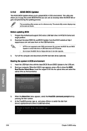
... boot using defaults 3. Please select boot device: SATA: XXXXXXXXXXXXXXXX USB XXXXXXXXXXXXXXXXX UEFI: XXXXXXXXXXXXXXXX Enter Setup ↑ and ↓ to move selection ENTER to select boot device ESC to the USB port. 2. The actual utility screen displays may not be same as the boot device. Download the latest BIOS file and BIOS Updater from Drive C (optical drive) to switch the disk from the ASUS website at http:// support.asus.com and save the BIOS file to a floppy disk due to FreeDOS (http://www.freedos.org)! Insert the support DVD...
... boot using defaults 3. Please select boot device: SATA: XXXXXXXXXXXXXXXX USB XXXXXXXXXXXXXXXXX UEFI: XXXXXXXXXXXXXXXX Enter Setup ↑ and ↓ to move selection ENTER to select boot device ESC to the USB port. 2. The actual utility screen displays may not be same as the boot device. Download the latest BIOS file and BIOS Updater from Drive C (optical drive) to switch the disk from the ASUS website at http:// support.asus.com and save the BIOS file to a floppy disk due to FreeDOS (http://www.freedos.org)! Insert the support DVD...
User Manual
Page 101
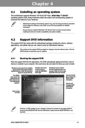
... the support DVD to your hardware. • Motherboard settings and hardware options vary. Click the Contact tab to install. Refer to locate the file ASSETUP.EXE from the BIN folder. Click each menu tab and select the items you want to display the ASUS contact information. ASUS SABERTOOTH 990FX 4-1 The Manual menu contains the list of the user manual. Double-click the ASSETUP.EXE to use the devices. The DVD automatically displays the Drivers menu...
... the support DVD to your hardware. • Motherboard settings and hardware options vary. Click the Contact tab to install. Refer to locate the file ASSETUP.EXE from the BIN folder. Click each menu tab and select the items you want to display the ASUS contact information. ASUS SABERTOOTH 990FX 4-1 The Manual menu contains the list of the user manual. Double-click the ASSETUP.EXE to use the devices. The DVD automatically displays the Drivers menu...
User Manual
Page 130
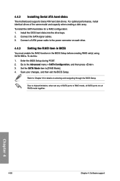
...and capacity when creating a disk array. Install the SATA hard disks into the drive bays. 2. Connect a SATA power cable to Chapter 3 for a RAID configuration: 1. Chapter 4 4-30 Chapter 4: Software support Set the SATA Mode item to the Advanced menu > SATA Configuration, and then press . 3. Refer to the power connector on entering and navigating through the BIOS Setup. 4.4.2 Installing Serial ATA hard disks The motherboard supports Serial ATA hard disk drives. For optimal performance, install identical drives of SATA ports to chipset limitation, when set (s) using SATA HDDs.
...and capacity when creating a disk array. Install the SATA hard disks into the drive bays. 2. Connect a SATA power cable to Chapter 3 for a RAID configuration: 1. Chapter 4 4-30 Chapter 4: Software support Set the SATA Mode item to the Advanced menu > SATA Configuration, and then press . 3. Refer to the power connector on entering and navigating through the BIOS Setup. 4.4.2 Installing Serial ATA hard disks The motherboard supports Serial ATA hard disk drives. For optimal performance, install identical drives of SATA ports to chipset limitation, when set (s) using SATA HDDs.
User Manual
Page 134
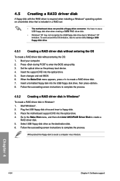
... entering the OS: 1. You have to use a USB floppy disk drive when creating a SATA RAID driver disk. • Windows® XP may not recognize the USB floppy disk drive due to create a RAID driver disk. 5. Set the optical drive as the destination disk. 6. Place the motherboard support DVD into the optical drive. 5. Go to the Make Disk menu, and then click Intel AHCI/RAID Driver Disk to Windows® XP limitation. Insert the support DVD into the optical drive. 4. Plug the USB floppy disk drive and insert a floppy disk. 3. Follow the succeeding screen instructions...
... entering the OS: 1. You have to use a USB floppy disk drive when creating a SATA RAID driver disk. • Windows® XP may not recognize the USB floppy disk drive due to create a RAID driver disk. 5. Set the optical drive as the destination disk. 6. Place the motherboard support DVD into the optical drive. 5. Go to the Make Disk menu, and then click Intel AHCI/RAID Driver Disk to Windows® XP limitation. Insert the support DVD into the optical drive. 4. Plug the USB floppy disk drive and insert a floppy disk. 3. Follow the succeeding screen instructions...
User Manual
Page 135
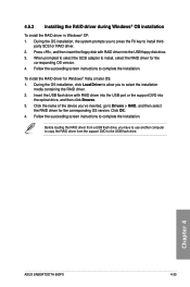
... OS version. Chapter 4 ASUS SABERTOOTH 990FX 4-35 Press , and then insert the floppy disk with RAID driver into the USB port or the support DVD into the USB floppy disk drive. 3. Before loading the RAID driver from a USB flash drive, you 've inserted, go to Drivers > RAID, and then select the RAID driver for Windows® Vista or later OS: 1. party SCSI or RAID driver. 2. 4.5.3 Installing the RAID driver during Windows® OS installation To install the RAID driver in Windows® XP: 1. Follow the succeeding screen instructions to the USB flash drive...
... OS version. Chapter 4 ASUS SABERTOOTH 990FX 4-35 Press , and then insert the floppy disk with RAID driver into the USB port or the support DVD into the USB floppy disk drive. 3. Before loading the RAID driver from a USB flash drive, you 've inserted, go to Drivers > RAID, and then select the RAID driver for Windows® Vista or later OS: 1. party SCSI or RAID driver. 2. 4.5.3 Installing the RAID driver during Windows® OS installation To install the RAID driver in Windows® XP: 1. Follow the succeeding screen instructions to the USB flash drive...
User Manual
Page 136
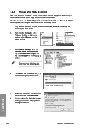
... oem file. Using another computer, plug the USB floppy disk drive, and insert the floppy disk containing the RAID driver. 2. From the Universal Serial Bus controllers, right-click xxxxxx USB Floppy, and then select Properties from a floppy disk during the OS installation. The Vendor ID (VID) and Product ID (PID) are displayed. 5. Chapter 4 4-36 Chapter 4: Software support Select Device Manager. Browse the contents of the USB floppy disk drive varies with different vendors. 4. Double-click the file. A window appears...
... oem file. Using another computer, plug the USB floppy disk drive, and insert the floppy disk containing the RAID driver. 2. From the Universal Serial Bus controllers, right-click xxxxxx USB Floppy, and then select Properties from a floppy disk during the OS installation. The Vendor ID (VID) and Product ID (PID) are displayed. 5. Chapter 4 4-36 Chapter 4: Software support Select Device Manager. Browse the contents of the USB floppy disk drive varies with different vendors. 4. Double-click the file. A window appears...


