User Manual
Page 11
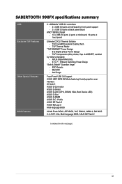
... - P. : Efficient Switching Power Disign "Safe & Stable!" S. Anti Surge Front Panel USB 3.0 Support ASUS UEFI BIOS EZ Mode featuring friendly graphics user interface AI Suite II ASUS Q-Connector ASUS Q-Shield ASUS Q-LED (CPU, DRAM, VGA, Boot Device LED) ASUS Q-Slot ASUS Q-DIMM ASUS O.C. Thermal Solution - certified by military-standard) - SABERTOOTH 990FX specifications summary USB Exclusive TUF Features Other Special Features BIOS Features 2 x ASMedia®...
... - P. : Efficient Switching Power Disign "Safe & Stable!" S. Anti Surge Front Panel USB 3.0 Support ASUS UEFI BIOS EZ Mode featuring friendly graphics user interface AI Suite II ASUS Q-Connector ASUS Q-Shield ASUS Q-LED (CPU, DRAM, VGA, Boot Device LED) ASUS Q-Slot ASUS Q-DIMM ASUS O.C. Thermal Solution - certified by military-standard) - SABERTOOTH 990FX specifications summary USB Exclusive TUF Features Other Special Features BIOS Features 2 x ASMedia®...

User Manual
Page 62
... table below) or additional messages appear on . Pressing the power switch for assistance. Connect the power cord to green after the system LED turns on the screen. External SCSI devices (starting with a surge protector. 5. While the tests are off. 3. If you press the ATX power button. Follow the instructions in the ... beeps then a pause (repeated) One continuous beep followed by three short beeps One continuous beep followed by four short beeps Description VGA detected Quick boot set to the power connector at the back of the BIOS setting. 2-44 Chapter 2: Hardware information
... table below) or additional messages appear on . Pressing the power switch for assistance. Connect the power cord to green after the system LED turns on the screen. External SCSI devices (starting with a surge protector. 5. While the tests are off. 3. If you press the ATX power button. Follow the instructions in the ... beeps then a pause (repeated) One continuous beep followed by three short beeps One continuous beep followed by four short beeps Description VGA detected Quick boot set to the power connector at the back of the BIOS setting. 2-44 Chapter 2: Hardware information


