User Manual
Page 6
... the correct voltage in any damage, contact your dealer immediately. • To avoid short circuits, keep paper clips, screws, and staples away from connectors, slots, sockets and circuitry. • Avoid dust, humidity, and temperature extremes. Do not place the product in your retailer. Operation safety • Before installing the motherboard and...
... the correct voltage in any damage, contact your dealer immediately. • To avoid short circuits, keep paper clips, screws, and staples away from connectors, slots, sockets and circuitry. • Avoid dust, humidity, and temperature extremes. Do not place the product in your retailer. Operation safety • Before installing the motherboard and...
User Manual
Page 9
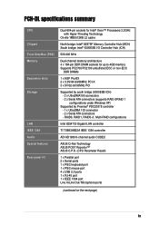
... CODEC ASUS Q-Fan Technology ASUS POST Reporter™ ASUS C.P.R. (CPU Parameter Recall) 1 x Parallel port 2 x Serial ports 1 x PS/2 keyboard port 1 x PS/2 mouse port 4 x USB 2.0 ports 1 x RJ-45 port 1 x IEEE 1394 port Line In/Line Out/ Microphone ports (continued on the next page) ix PCH-DL specifications ...summary CPU Chipset Front Side Bus (FSB) Memory Expansion slots Storage LAN IEEE 1394 Audio Special features Rear panel I/O Dual 604-pin sockets for Intel® Xeon™ Processors 3.2GHz with Hyper...
... CODEC ASUS Q-Fan Technology ASUS POST Reporter™ ASUS C.P.R. (CPU Parameter Recall) 1 x Parallel port 2 x Serial ports 1 x PS/2 keyboard port 1 x PS/2 mouse port 4 x USB 2.0 ports 1 x RJ-45 port 1 x IEEE 1394 port Line In/Line Out/ Microphone ports (continued on the next page) ix PCH-DL specifications ...summary CPU Chipset Front Side Bus (FSB) Memory Expansion slots Storage LAN IEEE 1394 Audio Special features Rear panel I/O Dual 604-pin sockets for Intel® Xeon™ Processors 3.2GHz with Hyper...
User Manual
Page 14
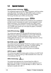
... to 150MB/s data transfer rate. 1.3 Special features Latest processor technology The motherboard supports dual Intel® Xeon™ Processors via 604-pin surface mount ZIF sockets. The processor has 1MB/512KB L2 cache, includes a 533/400MHz system bus, and features the Intel Hyper-Threading Technology that of system memory using Serial...
... to 150MB/s data transfer rate. 1.3 Special features Latest processor technology The motherboard supports dual Intel® Xeon™ Processors via 604-pin surface mount ZIF sockets. The processor has 1MB/512KB L2 cache, includes a 533/400MHz system bus, and features the Intel Hyper-Threading Technology that of system memory using Serial...
User Manual
Page 19
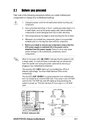
...AGP card. AGP_WARN1 ON Incorrect AGP Card OFF Correct AGP Card LED1 PCH-DL PCH-DL Onboard LED ON OFF CPU Type/Voltage CPU Type/Voltage not identical identical SB_PWR1 ON Standby Power OFF Powered Off ASUS PCH-DL Deluxe motherboard 2-1 Failure to do so may cause severe damage to ...you plug in soft-off mode, a reminder that came with the component. 5. The red LED (AGP_WARN1) is detached from the wall socket before you install motherboard components or change any motherboard settings. 1. Whenever you uninstall any motherboard component. This warning LED (LED1) lights ...
...AGP card. AGP_WARN1 ON Incorrect AGP Card OFF Correct AGP Card LED1 PCH-DL PCH-DL Onboard LED ON OFF CPU Type/Voltage CPU Type/Voltage not identical identical SB_PWR1 ON Standby Power OFF Powered Off ASUS PCH-DL Deluxe motherboard 2-1 Failure to do so may cause severe damage to ...you plug in soft-off mode, a reminder that came with the component. 5. The red LED (AGP_WARN1) is detached from the wall socket before you install motherboard components or change any motherboard settings. 1. Whenever you uninstall any motherboard component. This warning LED (LED1) lights ...
User Manual
Page 22
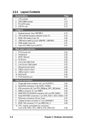
...2-4 Chapter 2: Hardware information Serial ATA connectors (7-pin SATA1, SATA2) 2-23 3. IEEE 1394 connector (10-1 pin IEEE1394_1) 2-28 10. CPU sockets 2. Floppy disk drive connector (34-1 pin FLOPPY1) 2-23 2. Clear RTC RAM (3-pin CLRTC1) 2-21 Rear panel connectors 1. RJ-45 port...keyboard port 2-22 Internal connectors 1. Parallel port 2-22 3. RAID ATA/133/100/66/33 connector (40-1 pin PRI_RAID1) 2-25 6. DDR DIMM sockets 3. AGP Pro slot Page 2-5 2-13 2-15 2-18 Jumpers 1. RAID enable (3-pin J2) 2-21 6. Serial ATA RAID connectors (7-pin SATA_RAID1,...
...2-4 Chapter 2: Hardware information Serial ATA connectors (7-pin SATA1, SATA2) 2-23 3. IEEE 1394 connector (10-1 pin IEEE1394_1) 2-28 10. CPU sockets 2. Floppy disk drive connector (34-1 pin FLOPPY1) 2-23 2. Clear RTC RAM (3-pin CLRTC1) 2-21 Rear panel connectors 1. RJ-45 port...keyboard port 2-22 Internal connectors 1. Parallel port 2-22 3. RAID ATA/133/100/66/33 connector (40-1 pin PRI_RAID1) 2-25 6. DDR DIMM sockets 3. AGP Pro slot Page 2-5 2-13 2-15 2-18 Jumpers 1. RAID enable (3-pin J2) 2-21 6. Serial ATA RAID connectors (7-pin SATA_RAID1,...
User Manual
Page 24
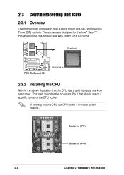
...Pin 1 that the CPU has a gold triangular mark on one CPU, use CPU socket 1 to ensure system stability.. The sockets are designed for CPU2 2-6 Chapter 2: Hardware information Prestonia PCH-DL PCH-DL Socket 604 Gold Arrow 2.3.2 Installing the CPU Note in the 604-pin package with dual ...surface mount 604-pin Zero Insertion Force (ZIF) sockets. Socket for CPU1 Socket for the Intel® Xeon™ Processor in the ...
...Pin 1 that the CPU has a gold triangular mark on one CPU, use CPU socket 1 to ensure system stability.. The sockets are designed for CPU2 2-6 Chapter 2: Hardware information Prestonia PCH-DL PCH-DL Socket 604 Gold Arrow 2.3.2 Installing the CPU Note in the 604-pin package with dual ...surface mount 604-pin Zero Insertion Force (ZIF) sockets. Socket for CPU1 Socket for the Intel® Xeon™ Processor in the ...
User Manual
Page 25
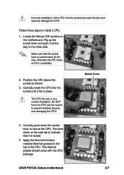
.... 5. This thermal grease should come with the CPU package. Carefully push down the socket lever to the top of the CPU into the socket may bend the pins and severely damage the CPU! ASUS PCH-DL Deluxe motherboard 2-7 Position the CPU above the socket as shown. 3. Apply the thermal interface material (thermal grease) to secure the...
.... 5. This thermal grease should come with the CPU package. Carefully push down the socket lever to the top of the CPU into the socket may bend the pins and severely damage the CPU! ASUS PCH-DL Deluxe motherboard 2-7 Position the CPU above the socket as shown. 3. Apply the thermal interface material (thermal grease) to secure the...
User Manual
Page 26
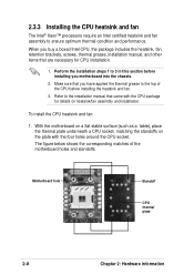
Make sure that came with the four holes around the CPU socket. Motherboard hole Standoff CPU thermal plate 2-8 Chapter 2: Hardware information Perform the installation steps 1 to ensure optimum thermal condition and performance. To install the ...plate with the CPU package for CPU installation. 1. With the motherboard on a flat stable surface (such as a table), place the thermal plate underneath a CPU socket, matching the standoffs on heatsink/fan assembly and installation. 2.3.3 Installing the CPU heatsink and fan The Intel® Xeon™ processors require an Intel certified...
Make sure that came with the four holes around the CPU socket. Motherboard hole Standoff CPU thermal plate 2-8 Chapter 2: Hardware information Perform the installation steps 1 to ensure optimum thermal condition and performance. To install the ...plate with the CPU package for CPU installation. 1. With the motherboard on a flat stable surface (such as a table), place the thermal plate underneath a CPU socket, matching the standoffs on heatsink/fan assembly and installation. 2.3.3 Installing the CPU heatsink and fan The Intel® Xeon™ processors require an Intel certified...
User Manual
Page 27
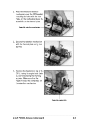
Secure the retention mechanism with cut corners) facing the memory sockets. Heatsink angled side ASUS PCH-DL Deluxe motherboard 2-9 Heatsink retention mechanism 3. Make sure that the heatsink base fits completely on the thermal plate. Position the heatsink on top of the CPU, having its holes with the four holes on the motherboard and the standoffs on the retention mechanism. Place the heatsink retention mechanism over the CPU socket, matching its angled side (with the thermal plate using four screws. 4. 2.
Secure the retention mechanism with cut corners) facing the memory sockets. Heatsink angled side ASUS PCH-DL Deluxe motherboard 2-9 Heatsink retention mechanism 3. Make sure that the heatsink base fits completely on the thermal plate. Position the heatsink on top of the CPU, having its holes with the four holes on the motherboard and the standoffs on the retention mechanism. Place the heatsink retention mechanism over the CPU socket, matching its angled side (with the thermal plate using four screws. 4. 2.
User Manual
Page 31
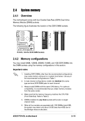
... Table 2. 5. DIMMs installed into the DIMM sockets using the memory configurations in this section. ASUS PCH-DL motherboard 2-13 The following figure illustrates the location of the recommended configurations in singlechannel mode. 6. When all four sockets are populated with the same CAS latency. For...sure that you obtain memory modules from the same vendor. 4. DIMM_B2 DIMM_A2 DIMM_B1 80 Pins DIMM_A1 104 Pins PCH-DL PCH-DL 184-Pin DDR DIMM Sockets 2.4.2 Memory configurations You may cause memory sizing error or system boot failure. In dual-channel configurations, install ...
... Table 2. 5. DIMMs installed into the DIMM sockets using the memory configurations in this section. ASUS PCH-DL motherboard 2-13 The following figure illustrates the location of the recommended configurations in singlechannel mode. 6. When all four sockets are populated with the same CAS latency. For...sure that you obtain memory modules from the same vendor. 4. DIMM_B2 DIMM_A2 DIMM_B1 80 Pins DIMM_A1 104 Pins PCH-DL PCH-DL 184-Pin DDR DIMM Sockets 2.4.2 Memory configurations You may cause memory sizing error or system boot failure. In dual-channel configurations, install ...
User Manual
Page 32
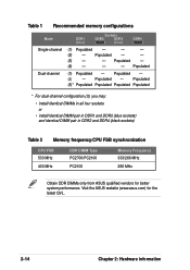
... pair in DDR2 and DDR4 (black sockets) Table 2 Memory frequency/CPU FSB synchronization CPU FSB 533 MHz 400 MHz DDR DIMM Type PC2700/PC2100 PC2100 Memory Frequency 333/266 MHz 266 MHz Obtain DDR DIMMs only from ASUS qualified vendors for the latest QVL. ...2-14 Chapter 2: Hardware information Visit the ASUS website (www.asus.com) for better system performance. Populated - - (3) - - Populated - (4) - - - Table 1 Recommended ...
... pair in DDR2 and DDR4 (black sockets) Table 2 Memory frequency/CPU FSB synchronization CPU FSB 533 MHz 400 MHz DDR DIMM Type PC2700/PC2100 PC2100 Memory Frequency 333/266 MHz 266 MHz Obtain DDR DIMMs only from ASUS qualified vendors for the latest QVL. ...2-14 Chapter 2: Hardware information Visit the ASUS website (www.asus.com) for better system performance. Populated - - (3) - - Populated - (4) - - - Table 1 Recommended ...
User Manual
Page 33
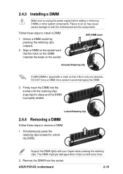
...with your fingers when pressing the retaining clips. The DIMM might get damaged when it fits in only one direction. ASUS PCH-DL motherboard 2-15 Firmly insert the DIMM into a socket to install a DIMM. 1. 2.4.3 Installing a DIMM Make sure to unlock the DIMM. Locked Retaining Clip 2.4.4 ...steps to avoid damaging the DIMM. 3. Support the DIMM lightly with extra force. 2. Align a DIMM on the socket. Remove the DIMM from the socket. Follow these steps to both the motherboard and the components. Simultaneously press the retaining clips outward to unplug the power...
...with your fingers when pressing the retaining clips. The DIMM might get damaged when it fits in only one direction. ASUS PCH-DL motherboard 2-15 Firmly insert the DIMM into a socket to install a DIMM. 1. 2.4.3 Installing a DIMM Make sure to unlock the DIMM. Locked Retaining Clip 2.4.4 ...steps to avoid damaging the DIMM. 3. Support the DIMM lightly with extra force. 2. Align a DIMM on the socket. Remove the DIMM from the socket. Follow these steps to both the motherboard and the components. Simultaneously press the retaining clips outward to unplug the power...
User Manual
Page 54
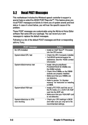
.... In case of a boot failure, you of the PCI slots, or a +0.8V/1.5V AGP card into the CPU socket. • Check the CPU if properly installed. • Call ASUS technical support for instruction on installing a DIMM. • Install a PCI VGA card into one of system events and boot... 3-2 Chapter 3: Powering up You can record your package. See the "ASUS contact information." • Install 184-pin unbuffered PC3200/2700/2100 DIMMs into the DIMM sockets. • Check if the DIMMs on the DIMM sockets are customizable using the Winbond Voice Editor software that your CPU settings in ...
.... In case of a boot failure, you of the PCI slots, or a +0.8V/1.5V AGP card into the CPU socket. • Check the CPU if properly installed. • Call ASUS technical support for instruction on installing a DIMM. • Install a PCI VGA card into one of system events and boot... 3-2 Chapter 3: Powering up You can record your package. See the "ASUS contact information." • Install 184-pin unbuffered PC3200/2700/2100 DIMMs into the DIMM sockets. • Check if the DIMMs on the DIMM sockets are customizable using the Winbond Voice Editor software that your CPU settings in ...


