User Manual
Page 3
... this guide vii PCH-DL specifications summary ix Chapter 1: Product introduction 1.1 Welcome 1-1 1.2 Package contents 1-1 1.3 Special features 1-2 Chapter 2: Hardware information 2.1 Before you proceed 2-1 2.2 Motherboard installation 2-2 2.2.1 Placement direction 2-2 2.2.2 Screw holes 2-2 2.2.3 Motherboard layout 2-3 2.2.4 Layout Contents 2-4 2.3 Central Processing Unit (CPU 2-5 2.3.1 Overview 2-5 2.3.2 Installing the CPU 2-5 2.3.3 Installing the CPU heatsink and fan 2-7 2.4 System memory 2-12 2.4.1 Overview 2-12 2.4.2 Memory configurations 2-12...
... this guide vii PCH-DL specifications summary ix Chapter 1: Product introduction 1.1 Welcome 1-1 1.2 Package contents 1-1 1.3 Special features 1-2 Chapter 2: Hardware information 2.1 Before you proceed 2-1 2.2 Motherboard installation 2-2 2.2.1 Placement direction 2-2 2.2.2 Screw holes 2-2 2.2.3 Motherboard layout 2-3 2.2.4 Layout Contents 2-4 2.3 Central Processing Unit (CPU 2-5 2.3.1 Overview 2-5 2.3.2 Installing the CPU 2-5 2.3.3 Installing the CPU heatsink and fan 2-7 2.4 System memory 2-12 2.4.1 Overview 2-12 2.4.2 Memory configurations 2-12...
User Manual
Page 4
...10 4.3.4 Secondary IDE Slave 4-10 4.3.5 Third IDE Master 4-11 4.3.6 Fourth IDE Master 4-11 4.4 Advanced menu 4-12 4.4.1 Advanced BIOS Features 4-12 4.4.2 CPU Configuration 4-13 4.4.3 Memory Configuration 4-14 4.4.4 Chipset 4-15 4.4.5 Onboard Device 4-18 4.4.6 Speech Configuration 4-22 4.4.7 PCIPnP 4-23 4.4.8 USB Configuration 4-25 4.5 Power menu 4-26 4.5.1 APM Configuration 4-27 ... Boot Priority 4-33 4.6.3 Removable Device Priority 4-33 4.6.4 Boot Settings Configuration 4-34 4.6.5 Security 4-35 4.7 Exit menu 4-37 Appendix: Reference information A.1 PCH-DL block diagram A-1 iv
...10 4.3.4 Secondary IDE Slave 4-10 4.3.5 Third IDE Master 4-11 4.3.6 Fourth IDE Master 4-11 4.4 Advanced menu 4-12 4.4.1 Advanced BIOS Features 4-12 4.4.2 CPU Configuration 4-13 4.4.3 Memory Configuration 4-14 4.4.4 Chipset 4-15 4.4.5 Onboard Device 4-18 4.4.6 Speech Configuration 4-22 4.4.7 PCIPnP 4-23 4.4.8 USB Configuration 4-25 4.5 Power menu 4-26 4.5.1 APM Configuration 4-27 ... Boot Priority 4-33 4.6.3 Removable Device Priority 4-33 4.6.4 Boot Settings Configuration 4-34 4.6.5 Security 4-35 4.7 Exit menu 4-37 Appendix: Reference information A.1 PCH-DL block diagram A-1 iv
User Manual
Page 9
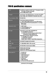
...PCH-DL specifications summary CPU Chipset Front Side Bus (FSB) Memory Expansion slots Storage LAN IEEE 1394 Audio Special features Rear panel I/O Dual 604-pin sockets for Intel® Xeon™ Processors 3.2GHz with Hyper-Threding Technology On-die 1MB/512KB L2 cache North bridge: Intel® 82875P Memory..., RAID0+1, Multi-RAID configurations Intel 82547GI Gigabit LAN controller TI TSB43AB22A IEEE 1394 controller ADI AD1980 6-channel audio CODEC ASUS Q-Fan Technology ASUS POST Reporter™ ASUS C.P.R. (CPU Parameter Recall) 1 x Parallel port 2 x Serial ports 1 x PS/2 keyboard port 1 x ...
...PCH-DL specifications summary CPU Chipset Front Side Bus (FSB) Memory Expansion slots Storage LAN IEEE 1394 Audio Special features Rear panel I/O Dual 604-pin sockets for Intel® Xeon™ Processors 3.2GHz with Hyper-Threding Technology On-die 1MB/512KB L2 cache North bridge: Intel® 82875P Memory..., RAID0+1, Multi-RAID configurations Intel 82547GI Gigabit LAN controller TI TSB43AB22A IEEE 1394 controller ADI AD1980 6-channel audio CODEC ASUS Q-Fan Technology ASUS POST Reporter™ ASUS C.P.R. (CPU Parameter Recall) 1 x Parallel port 2 x Serial ports 1 x PS/2 keyboard port 1 x ...
User Manual
Page 13
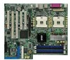
... making it , check the items in your package with the list below. 1.2 Package contents Check your PCH-DL package for buying the ASUS® PCH-DL motherboard! The motherboard incorporates the Intel® Xeon™ processor in 604-pin package coupled with dual-channel... to provide a powerful workstation platform solution. ASUS PCH-DL motherboard 1-1 Before you for the following items. ASUS PCH-DL motherboard ASUS support CD 4 x SATA cables 2 x SATA power cables 3 x UltraDMA100/66 IDE and floppy drive cables (4-in the world of system memory with the Intel® 82875P chipset to ...
... making it , check the items in your package with the list below. 1.2 Package contents Check your PCH-DL package for buying the ASUS® PCH-DL motherboard! The motherboard incorporates the Intel® Xeon™ processor in 604-pin package coupled with dual-channel... to provide a powerful workstation platform solution. ASUS PCH-DL motherboard 1-1 Before you for the following items. ASUS PCH-DL motherboard ASUS support CD 4 x SATA cables 2 x SATA power cables 3 x UltraDMA100/66 IDE and floppy drive cables (4-in the world of system memory with the Intel® 82875P chipset to ...
User Manual
Page 14
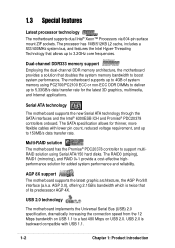
... has 1MB/512KB L2 cache, includes a 533/400MHz system bus, and features the Intel Hyper-Threading Technology that of system memory using Serial ATA/150 hard disks. AGP 3.0), offering 2.1GB/s bandwidth which is backward compatible with lower pin count, reduced ...thinner, more flexible cables with USB 1.1. 1-2 Chapter 1: Product introduction Dual-channel DDR333 memory support Employing the dual-channel DDR memory architecture, the motherboard provides a solution that doubles the system memory bandwidth to a fast 480 Mbps on USB 2.0. 1.3 Special features Latest processor technology...
... has 1MB/512KB L2 cache, includes a 533/400MHz system bus, and features the Intel Hyper-Threading Technology that of system memory using Serial ATA/150 hard disks. AGP 3.0), offering 2.1GB/s bandwidth which is backward compatible with lower pin count, reduced ...thinner, more flexible cables with USB 1.1. 1-2 Chapter 1: Product introduction Dual-channel DDR333 memory support Employing the dual-channel DDR memory architecture, the motherboard provides a solution that doubles the system memory bandwidth to a fast 480 Mbps on USB 2.0. 1.3 Special features Latest processor technology...
User Manual
Page 15
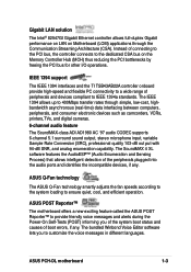
...LAN on the Memory Controller Hub (MCH) thus reducing the PCI bottlenecks by freeing the PCI bus for other I/O operations. The IEEE 1394 allows up to 400Mbps transfer rates through the Communication Streaming Architecture (CSA). ASUS Q-Fan technology The ASUS Q-Fan technology smartly...) informing you to IEEE 1394a standards. Instead of peripherals and devices compliant to customize the voice messages in different languages. ASUS PCH-DL motherboard 1-3 IEEE 1394 support The IEEE 1394 interfaces and the TI TSB43AB22A controller onboard provide high-speed and flexible PC connectivity...
...LAN on the Memory Controller Hub (MCH) thus reducing the PCI bottlenecks by freeing the PCI bus for other I/O operations. The IEEE 1394 allows up to 400Mbps transfer rates through the Communication Streaming Architecture (CSA). ASUS Q-Fan technology The ASUS Q-Fan technology smartly...) informing you to IEEE 1394a standards. Instead of peripherals and devices compliant to customize the voice messages in different languages. ASUS PCH-DL motherboard 1-3 IEEE 1394 support The IEEE 1394 interfaces and the TI TSB43AB22A controller onboard provide high-speed and flexible PC connectivity...
User Manual
Page 18
Chapter summary 2.1 Before you proceed 2-1 2.2 Motherboard installation 2-2 2.3 Central Processing Unit (CPU 2-5 2.4 System memory 2-12 2.5 Expansion slots 2-15 2.6 Jumpers 2-18 2.7 Connectors 2-21 ASUS PCH-DL motherboard
Chapter summary 2.1 Before you proceed 2-1 2.2 Motherboard installation 2-2 2.3 Central Processing Unit (CPU 2-5 2.4 System memory 2-12 2.5 Expansion slots 2-15 2.6 Jumpers 2-18 2.7 Connectors 2-21 ASUS PCH-DL motherboard
User Manual
Page 27
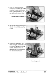
Heatsink retention mechanism 3. Make sure that the heatsink base fits completely on top of the CPU, having its holes with the four holes on the motherboard and the standoffs on the thermal plate. Heatsink angled side ASUS PCH-DL Deluxe motherboard 2-9 Position the heatsink on the retention mechanism. Place the heatsink retention mechanism over the CPU socket, matching its angled side (with the thermal plate using four screws. 4. Secure the retention mechanism with cut corners) facing the memory sockets. 2.
Heatsink retention mechanism 3. Make sure that the heatsink base fits completely on top of the CPU, having its holes with the four holes on the motherboard and the standoffs on the thermal plate. Heatsink angled side ASUS PCH-DL Deluxe motherboard 2-9 Position the heatsink on the retention mechanism. Place the heatsink retention mechanism over the CPU socket, matching its angled side (with the thermal plate using four screws. 4. Secure the retention mechanism with cut corners) facing the memory sockets. 2.
User Manual
Page 31
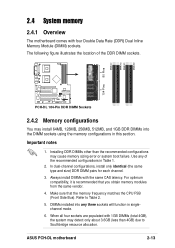
...Southbridge resource allocation. ASUS PCH-DL motherboard 2-13 Installing DDR DIMMs other than the recommended configurations may detect only about 3.6GB (less than 4GB) due to Table 2. 5. Use any three sockets will function in singlechannel mode. 6. Make sure that you obtain memory modules from the...illustrates the location of the recommended configurations in this section. DIMM_B2 DIMM_A2 DIMM_B1 80 Pins DIMM_A1 104 Pins PCH-DL PCH-DL 184-Pin DDR DIMM Sockets 2.4.2 Memory configurations You may install 64MB, 128MB, 256MB, 512MB, and 1GB DDR DIMMs into any of the ...
...Southbridge resource allocation. ASUS PCH-DL motherboard 2-13 Installing DDR DIMMs other than the recommended configurations may detect only about 3.6GB (less than 4GB) due to Table 2. 5. Use any three sockets will function in singlechannel mode. 6. Make sure that you obtain memory modules from the...illustrates the location of the recommended configurations in this section. DIMM_B2 DIMM_A2 DIMM_B1 80 Pins DIMM_A1 104 Pins PCH-DL PCH-DL 184-Pin DDR DIMM Sockets 2.4.2 Memory configurations You may install 64MB, 128MB, 256MB, 512MB, and 1GB DDR DIMMs into any of the ...
User Manual
Page 32
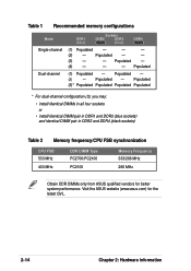
... Populated - (4) - - - Populated - Table 1 Recommended memory configurations Mode Single-channel Dual-channel DDR1 (blue) Sockets DDR2 DDR3 (black) (blue) DDR4 (black) (1) Populated - - - (2) - Populated - (2) - Populated (1) Populated - Visit the ASUS website (www.asus.com) for better system performance. Populated (3)* Populated Populated Populated ...sockets) Table 2 Memory frequency/CPU FSB synchronization CPU FSB 533 MHz 400 MHz DDR DIMM Type PC2700/PC2100 PC2100 Memory Frequency 333/266 MHz 266 MHz Obtain DDR DIMMs only from ASUS qualified vendors for ...
... Populated - (4) - - - Populated - Table 1 Recommended memory configurations Mode Single-channel Dual-channel DDR1 (blue) Sockets DDR2 DDR3 (black) (blue) DDR4 (black) (1) Populated - - - (2) - Populated - (2) - Populated (1) Populated - Visit the ASUS website (www.asus.com) for better system performance. Populated (3)* Populated Populated Populated ...sockets) Table 2 Memory frequency/CPU FSB synchronization CPU FSB 533 MHz 400 MHz DDR DIMM Type PC2700/PC2100 PC2100 Memory Frequency 333/266 MHz 266 MHz Obtain DDR DIMMs only from ASUS qualified vendors for ...
User Manual
Page 53
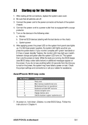
... the back of Beeps 2 3 4 6 7 8 10 Description Parity error Main memory read/write test error Motherboard timer not operational Keyboard controller BAT test error General exception error Display memory error CMOS shutdown register read/write error 7. Monitor b. The system then runs the ...power-on , hold down to a power outlet that all the connections, replace the system case cover. 2. While the tests are off. 3. Connect the power cord to enter BIOS Setup. System power 6. ASUS PCH-DL...
... the back of Beeps 2 3 4 6 7 8 10 Description Parity error Main memory read/write test error Motherboard timer not operational Keyboard controller BAT test error General exception error Display memory error CMOS shutdown register read/write error 7. Monitor b. The system then runs the ...power-on , hold down to a power outlet that all the connections, replace the system case cover. 2. While the tests are off. 3. Connect the power cord to enter BIOS Setup. System power 6. ASUS PCH-DL...
User Manual
Page 54
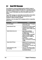
... the PCI slots, or a +0.8V/1.5V AGP card into the CPU socket. • Check the CPU if properly installed. • Call ASUS technical support for instruction on the DIMM sockets are properly installed. • Make sure that came with your own messages to replace the default messages... Powering up This feature gives you vocal POST messages and alerts to support a special feature called the ASUS POST Reporter™. POST message No CPU installed System failed CPU test System failed memory test System failed VGA test System failed due to CPU over-clocking Action • Install an Intel&#...
... the PCI slots, or a +0.8V/1.5V AGP card into the CPU socket. • Check the CPU if properly installed. • Call ASUS technical support for instruction on the DIMM sockets are properly installed. • Make sure that came with your own messages to replace the default messages... Powering up This feature gives you vocal POST messages and alerts to support a special feature called the ASUS POST Reporter™. POST message No CPU installed System failed CPU test System failed memory test System failed VGA test System failed due to CPU over-clocking Action • Install an Intel&#...
User Manual
Page 62
...) Legacy Diskette A Floppy 3 Mode Support Primary IDE Master Primary IDE Slave Secondary IDE Master Secondary IDE Slave Third IDE Master Fourth IDE Master Base Memory Extended Memory Total Memory 11: 10 : 30 Wed, Mar 24 2004 [1.44M, 3.5 in.] [Disabled] [None] [None] [None] [None] [None] [None] 640K 261120K 26114K Select Menu Item Specific Help...
...) Legacy Diskette A Floppy 3 Mode Support Primary IDE Master Primary IDE Slave Secondary IDE Master Secondary IDE Slave Third IDE Master Fourth IDE Master Base Memory Extended Memory Total Memory 11: 10 : 30 Wed, Mar 24 2004 [1.44M, 3.5 in.] [Disabled] [None] [None] [None] [None] [None] [None] 640K 261120K 26114K Select Menu Item Specific Help...

User Manual
Page 64
...:yy) Legacy Diskette A Floppy 3 Mode Support Primary IDE Master Primary IDE Slave Secondary IDE Master Secondary IDE Slave Third IDE Master Fourth IDE Master Base Memory Extended Memory Total Memory 11: 10 : 30 Wed, Mar 24 2004 [1.44M, 3.5 in .] Sets the type of 1.2MB (as opposed to 2099).
...:yy) Legacy Diskette A Floppy 3 Mode Support Primary IDE Master Primary IDE Slave Secondary IDE Master Secondary IDE Slave Third IDE Master Fourth IDE Master Base Memory Extended Memory Total Memory 11: 10 : 30 Wed, Mar 24 2004 [1.44M, 3.5 in .] Sets the type of 1.2MB (as opposed to 2099).
User Manual
Page 65
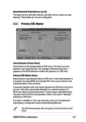
Base/Extended/Total Memory [xxxK] The base memory, extended memory, and total memory values are removing a drive and not replacing it, select [None]. If the drive was already formatted on a previous system, the BIOS may be because the ... the IDE drive parameters. appears as the BIOS attempts to the section "Manually detecting an IDE drive." These fields are grayed out when this channel. ASUS PCH-DL motherboard 4-7 Refer to detect the presence of a IDE drive.
Base/Extended/Total Memory [xxxK] The base memory, extended memory, and total memory values are removing a drive and not replacing it, select [None]. If the drive was already formatted on a previous system, the BIOS may be because the ... the IDE drive parameters. appears as the BIOS attempts to the section "Manually detecting an IDE drive." These fields are grayed out when this channel. ASUS PCH-DL motherboard 4-7 Refer to detect the presence of a IDE drive.
User Manual
Page 70
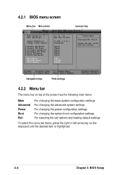
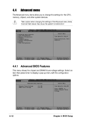
... Voltage DRAM Vcore Voltage [+1.6V] [+2.6V] Select Menu Item Specific Help Press [ENTER] to change the settings for the CPU, memory, chipset, and other system devices. Advanced BIOS Features CPU Configuration Memory Configuration Chipset Onboard Device Speech Configuration PCIPnP USB Configuration Select Menu Item Specific Help Virus Protection, Boot Sequence... 4.4.1 Advanced BIOS...
... Voltage DRAM Vcore Voltage [+1.6V] [+2.6V] Select Menu Item Specific Help Press [ENTER] to change the settings for the CPU, memory, chipset, and other system devices. Advanced BIOS Features CPU Configuration Memory Configuration Chipset Onboard Device Speech Configuration PCIPnP USB Configuration Select Menu Item Specific Help Virus Protection, Boot Sequence... 4.4.1 Advanced BIOS...
User Manual
Page 72
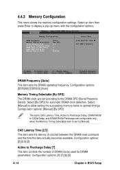
...to Precharge Delay [7] This item controls the number of DRAM clocks used for automatic DRAM clock detection. Select [Manual] to allow setting the succeeding memory items to display a pop-up menu with the configuration options. Configuration options: [Manual] [By SPD] The items CAS Latency Time, Active to... Precharge Delay, DRAM RAS# to CAS# Delay, and DRAM RAS# Precharge are set to CAS# Delay DRAM RAS# Precharge Memory Parity Check [Auto] [By SPD] 2.5 7 3 3 Enabled Select Menu Item Specific Help Set DRAM Frequency. Select an item then press Enter to ...
...to Precharge Delay [7] This item controls the number of DRAM clocks used for automatic DRAM clock detection. Select [Manual] to allow setting the succeeding memory items to display a pop-up menu with the configuration options. Configuration options: [Manual] [By SPD] The items CAS Latency Time, Active to... Precharge Delay, DRAM RAS# to CAS# Delay, and DRAM RAS# Precharge are set to CAS# Delay DRAM RAS# Precharge Memory Parity Check [Auto] [By SPD] 2.5 7 3 3 Enabled Select Menu Item Specific Help Set DRAM Frequency. Select an item then press Enter to ...

User Manual
Page 73
... the cache function of the system BIOS. Configuration options: [Disabled] [Enabled] ASUS PCH-DL motherboard 4-15 DRAM RAS# to set to [Enabled] improves the display speed by default. 4.4.4 Chipset This menu shows the chipset configuration settings. Configuration options: [4] [3] [2] Memory Parity Check [Enabled] Allows memory parity checking option (ECC). Chipset AGP Bridge Configuration Frequency/Voltage Control...
... the cache function of the system BIOS. Configuration options: [Disabled] [Enabled] ASUS PCH-DL motherboard 4-15 DRAM RAS# to set to [Enabled] improves the display speed by default. 4.4.4 Chipset This menu shows the chipset configuration settings. Configuration options: [4] [3] [2] Memory Parity Check [Enabled] Allows memory parity checking option (ECC). Chipset AGP Bridge Configuration Frequency/Voltage Control...

User Manual
Page 74
... options: [Disabled] [- 0.40%] [- 0.50%] [- 0.60%] [- 1.00%] AGP Bridge Configuration AGP Bridge Configuration AGP Aperture Size (MB) [128] Select Menu Item Specific Help Size of mapped memory for AGP graphic data. Configuration options: [Enabled] [Disabled] Spread Spectrum [- 0.50%] Allows you to select the maximum PCI bus speed to be porgrammed. Configuration options...
... options: [Disabled] [- 0.40%] [- 0.50%] [- 0.60%] [- 1.00%] AGP Bridge Configuration AGP Bridge Configuration AGP Aperture Size (MB) [128] Select Menu Item Specific Help Size of mapped memory for AGP graphic data. Configuration options: [Enabled] [Disabled] Spread Spectrum [- 0.50%] Allows you to select the maximum PCI bus speed to be porgrammed. Configuration options...


