User Manual
Page 9
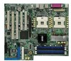
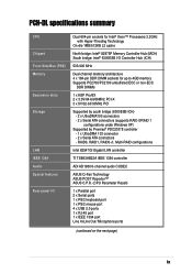
... RAID0+1, Multi-RAID configurations Intel 82547GI Gigabit LAN controller TI TSB43AB22A IEEE 1394 controller ADI AD1980 6-channel audio CODEC ASUS Q-Fan Technology ASUS POST Reporter™ ASUS C.P.R. (CPU Parameter Recall) 1 x Parallel port 2 x Serial ports 1 x PS/2 keyboard port 1 x PS/2 mouse port 4 x USB 2.0 ports 1 x RJ-45 port 1 x IEEE 1394 port Line In/Line Out/ Microphone ports (continued on the next page) ix PCH-DL specifications summary CPU Chipset Front Side Bus (FSB) Memory Expansion slots Storage LAN IEEE 1394 Audio Special features Rear panel I/O Dual 604-pin sockets for Intel...
... RAID0+1, Multi-RAID configurations Intel 82547GI Gigabit LAN controller TI TSB43AB22A IEEE 1394 controller ADI AD1980 6-channel audio CODEC ASUS Q-Fan Technology ASUS POST Reporter™ ASUS C.P.R. (CPU Parameter Recall) 1 x Parallel port 2 x Serial ports 1 x PS/2 keyboard port 1 x PS/2 mouse port 4 x USB 2.0 ports 1 x RJ-45 port 1 x IEEE 1394 port Line In/Line Out/ Microphone ports (continued on the next page) ix PCH-DL specifications summary CPU Chipset Front Side Bus (FSB) Memory Expansion slots Storage LAN IEEE 1394 Audio Special features Rear panel I/O Dual 604-pin sockets for Intel...
User Manual
Page 10
.../CHASSIS fan connectors 24-pin/8-pin SSI-type 12V power connectors 20-pin front panel connectors Chassis intrusion connector 1 x IEEE 1394 connector GAME/MIDI connector S/PDIF Out connector CD/AUX/Modem connectors Front panel audio connector 4Mb Flash ROM, Phoenix-Award BIOS, PnP, DMI2.0, WfM2.0, SM BIOS2.3 PCI 2.2, PCI-X 1.0a, USB 2.0 WfM 2.0. DMI 2.0, WOL/WOR by PME, chassis intrusion SSI-type power supply (with 24-pin and 8-pin power plugs) Extended ATX form factor: 12in x 10.5in (30.5cm x 26.7cm) Device drivers Management software System utilities ASUS contact information *Specifications...
.../CHASSIS fan connectors 24-pin/8-pin SSI-type 12V power connectors 20-pin front panel connectors Chassis intrusion connector 1 x IEEE 1394 connector GAME/MIDI connector S/PDIF Out connector CD/AUX/Modem connectors Front panel audio connector 4Mb Flash ROM, Phoenix-Award BIOS, PnP, DMI2.0, WfM2.0, SM BIOS2.3 PCI 2.2, PCI-X 1.0a, USB 2.0 WfM 2.0. DMI 2.0, WOL/WOR by PME, chassis intrusion SSI-type power supply (with 24-pin and 8-pin power plugs) Extended ATX form factor: 12in x 10.5in (30.5cm x 26.7cm) Device drivers Management software System utilities ASUS contact information *Specifications...
User Manual
Page 13
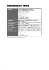
..., high-resolution graphics via an AGP Pro/ 8X slot, Serial ATA support, IEEE 1394, USB 2.0, and 6-channel audio features, the PCH-DL Deluxe is damaged or missing, contact your PCH-DL package for buying the ASUS® PCH-DL motherboard! ASUS PCH-DL motherboard 1-1 Supporting 533 MHz FSB, up to 4GB of system memory with the Intel® 82875P chipset to get ahead in the long line of power computing! Thank you start installing the motherboard, and hardware devices on...
..., high-resolution graphics via an AGP Pro/ 8X slot, Serial ATA support, IEEE 1394, USB 2.0, and 6-channel audio features, the PCH-DL Deluxe is damaged or missing, contact your PCH-DL package for buying the ASUS® PCH-DL motherboard! ASUS PCH-DL motherboard 1-1 Supporting 533 MHz FSB, up to 4GB of system memory with the Intel® 82875P chipset to get ahead in the long line of power computing! Thank you start installing the motherboard, and hardware devices on...
User Manual
Page 15
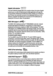
... system boot status and causes of the peripherals plugged into the audio ports and identifies the incompatible devices, if any . ASUS Q-Fan technology The ASUS Q-Fan technology smartly adjusts the fan speeds according to the system loading to IEEE 1394a standards. Gigabit LAN solution The Intel® 82547GI Gigabit Ethernet controller allows full-duplex Gigabit performance on LAN on the Memory Controller Hub (MCH) thus reducing the PCI bottlenecks by freeing the PCI bus...
... system boot status and causes of the peripherals plugged into the audio ports and identifies the incompatible devices, if any . ASUS Q-Fan technology The ASUS Q-Fan technology smartly adjusts the fan speeds according to the system loading to IEEE 1394a standards. Gigabit LAN solution The Intel® 82547GI Gigabit Ethernet controller allows full-duplex Gigabit performance on LAN on the Memory Controller Hub (MCH) thus reducing the PCI bottlenecks by freeing the PCI bus...
User Manual
Page 22
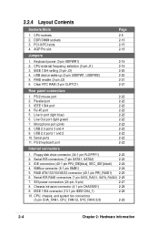
PCI-X/PCI slots 4. AGP Pro slot Page 2-5 2-13 2-15 2-18 Jumpers 1. RJ-45 port 2-22 5. Line Out port (light green) 2-22 7. Serial ports 2-22 11. CPU sockets 2. USB device wake-up (3-pin USBPW1, USBPW2) 2-20 5. Clear RTC RAM (3-pin CLRTC1) 2-21 Rear panel connectors 1. Line In port (light blue) 2-22 6. Chassis intrusion connector (4-1 pin CHASSIS1) 2-28 9. CPU, chassis, and system fan connectors (3-pin CHA_FAN1, CPU_FAN1/2, SYS_FAN1/2/3) 2-29 2-4 Chapter 2: Hardware information RAID enable (3-pin J2) 2-21 6. IEEE 1394 port 2-22 4. Serial ATA ...
PCI-X/PCI slots 4. AGP Pro slot Page 2-5 2-13 2-15 2-18 Jumpers 1. RJ-45 port 2-22 5. Line Out port (light green) 2-22 7. Serial ports 2-22 11. CPU sockets 2. USB device wake-up (3-pin USBPW1, USBPW2) 2-20 5. Clear RTC RAM (3-pin CLRTC1) 2-21 Rear panel connectors 1. Line In port (light blue) 2-22 6. Chassis intrusion connector (4-1 pin CHASSIS1) 2-28 9. CPU, chassis, and system fan connectors (3-pin CHA_FAN1, CPU_FAN1/2, SYS_FAN1/2/3) 2-29 2-4 Chapter 2: Hardware information RAID enable (3-pin J2) 2-21 6. IEEE 1394 port 2-22 4. Serial ATA ...
User Manual
Page 34
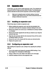
... the chassis with it by adjusting the software settings. 1. Replace the system cover. 2.5.2 Configuring an expansion card After installing the expansion card, configure it and make the necessary hardware settings for later use . Assign an IRQ to unplug the power cord before adding or removing expansion cards. 2.5 Expansion slots In the future, you intend to use . 4. The motherboard has two 64-bit PCI-X slots and three 32-bit PCI slots. Before installing the expansion card...
... the chassis with it by adjusting the software settings. 1. Replace the system cover. 2.5.2 Configuring an expansion card After installing the expansion card, configure it and make the necessary hardware settings for later use . Assign an IRQ to unplug the power cord before adding or removing expansion cards. 2.5 Expansion slots In the future, you intend to use . 4. The motherboard has two 64-bit PCI-X slots and three 32-bit PCI slots. Before installing the expansion card...
User Manual
Page 35
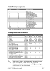
USB controller #2 IRQ_D# Onbd. LAN controller (Intel 82547GI) IRQ_F# Onbd. ASUS PCH-DL motherboard 2-17 Standard interrupt assignments IRQ Priority Standard Function 0 1 System Timer 1 2 Keyboard Controller 2 N/A Programmable Interrupt 3* 11 Communications Port (COM2) 4* 12 Communications Port (COM1) 5* 13 Sound Card (sometimes LPT2) 6 14 Floppy Disk Controller 7* 15 Printer Port (LPT1) 8 3 System CMOS/Real Time Clock 9* 4 ACPI Mode when used 10* 5 IRQ Holder for PCI Steering 11* 6 IRQ Holder for PCI Steering 12* 7 PS/2 Compatible Mouse Port ...
USB controller #2 IRQ_D# Onbd. LAN controller (Intel 82547GI) IRQ_F# Onbd. ASUS PCH-DL motherboard 2-17 Standard interrupt assignments IRQ Priority Standard Function 0 1 System Timer 1 2 Keyboard Controller 2 N/A Programmable Interrupt 3* 11 Communications Port (COM2) 4* 12 Communications Port (COM1) 5* 13 Sound Card (sometimes LPT2) 6 14 Floppy Disk Controller 7* 15 Printer Port (LPT1) 8 3 System CMOS/Real Time Clock 9* 4 ACPI Mode when used 10* 5 IRQ Holder for PCI Steering 11* 6 IRQ Holder for PCI Steering 12* 7 PS/2 Compatible Mouse Port ...
User Manual
Page 37
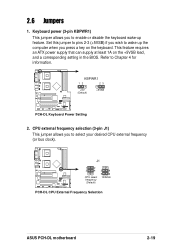
... lead, and a corresponding setting in the BIOS. J1 1 2 3 4 CPU select frequency (Default) 3 4 5 6 100MHz PCH-DL PCH-DL CPU External Frequency Selection ASUS PCH-DL motherboard 2-19 Keyboard power (3-pin KBPWR1) This jumper allows you to Chapter 4 for information. Refer to select your desired CPU external frequency (or bus clock). CPU external frequency selection (3-pin J1) This jumper allows you to wake up feature. KBPWR1 12 23 +5V (Default) +5VSB PCH-DL PCH-DL Keyboard Power Setting 2. This feature requires an ATX power supply that can supply at least 1A on...
... lead, and a corresponding setting in the BIOS. J1 1 2 3 4 CPU select frequency (Default) 3 4 5 6 100MHz PCH-DL PCH-DL CPU External Frequency Selection ASUS PCH-DL motherboard 2-19 Keyboard power (3-pin KBPWR1) This jumper allows you to Chapter 4 for information. Refer to select your desired CPU external frequency (or bus clock). CPU external frequency selection (3-pin J1) This jumper allows you to wake up feature. KBPWR1 12 23 +5V (Default) +5VSB PCH-DL PCH-DL Keyboard Power Setting 2. This feature requires an ATX power supply that can supply at least 1A on...
User Manual
Page 38
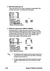
USB device wake-up (3-pin USBPW1, USBPW2) Set these jumpers to +5V to enable or disable the onboard IEEE 1394 controller. IEEE 1394 setting (3-pin J3) This jumper allows you to wake up from S1 sleep mode (CPU stopped, DRAM refreshed, system running in low power mode) using the connected USB devices. PCH-DL PCH-DL 1394 Function Setting J3 12 23 Enable (Default) Disable 4. Set to +5VSB to wake up the computer from S3 and S4 sleep modes (no power to activate the 1394 feature. Otherwise, the...
USB device wake-up (3-pin USBPW1, USBPW2) Set these jumpers to +5V to enable or disable the onboard IEEE 1394 controller. IEEE 1394 setting (3-pin J3) This jumper allows you to wake up from S1 sleep mode (CPU stopped, DRAM refreshed, system running in low power mode) using the connected USB devices. PCH-DL PCH-DL 1394 Function Setting J3 12 23 Enable (Default) Disable 4. Set to +5VSB to wake up the computer from S3 and S4 sleep modes (no power to activate the 1394 feature. Otherwise, the...
User Manual
Page 39
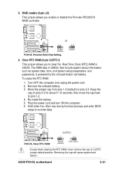
... battery. 5. The RAM data in CMOS. Move the jumper cap from pins 1-2 (default) to clear the Real Time Clock (RTC) RAM in CMOS, that include system setup information such as system date, time, and system setup parameters, and passwords, is powered by the onboard button cell battery. Hold down the key during the boot process and enter BIOS setup to pins 1-2. 4. ASUS PCH-DL motherboard 2-21 J2 12 23 Enable (Default) PCH-DL PCH-DL Promise Raid Chip Setting Disable 6. Turn OFF the computer and unplug the power cord. 2. 5. RAID enable (3-pin...
... battery. 5. The RAM data in CMOS. Move the jumper cap from pins 1-2 (default) to clear the Real Time Clock (RTC) RAM in CMOS, that include system setup information such as system date, time, and system setup parameters, and passwords, is powered by the onboard button cell battery. Hold down the key during the boot process and enter BIOS setup to pins 1-2. 4. ASUS PCH-DL motherboard 2-21 J2 12 23 Enable (Default) PCH-DL PCH-DL Promise Raid Chip Setting Disable 6. Turn OFF the computer and unplug the power cord. 2. 5. RAID enable (3-pin...
User Manual
Page 70
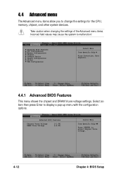
... to display a pop-up menu with the configuration options. Advanced BIOS Features CPU Configuration Memory Configuration Chipset Onboard Device Speech Configuration PCIPnP USB Configuration Select Menu Item Specific Help Virus Protection, Boot Sequence... 4.4.1 Advanced BIOS Features This menu shows the chipset and DRAM Vcore voltage settings. Advanced BIOS Features Chipset Vcore Voltage DRAM Vcore Voltage [+1.6V] [+2.6V] Select Menu Item Specific Help Press [ENTER] to change the settings for the CPU, memory, chipset, and other system devices. 4.4 Advanced menu The Advanced menu items...
... to display a pop-up menu with the configuration options. Advanced BIOS Features CPU Configuration Memory Configuration Chipset Onboard Device Speech Configuration PCIPnP USB Configuration Select Menu Item Specific Help Virus Protection, Boot Sequence... 4.4.1 Advanced BIOS Features This menu shows the chipset and DRAM Vcore voltage settings. Advanced BIOS Features Chipset Vcore Voltage DRAM Vcore Voltage [+1.6V] [+2.6V] Select Menu Item Specific Help Press [ENTER] to change the settings for the CPU, memory, chipset, and other system devices. 4.4 Advanced menu The Advanced menu items...
User Manual
Page 71
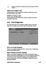
Select an item then press Enter to enable or disable the CPU Hyper-Threading Technology feature. Configuration options: [Disabled] [Enabled] Hyper-Threading Technolody [Enabled] Allows you to display a pop-up menu with the configuration options. Configuration options: [+1.5V] [+1.6V] [+1.7V] [+1.8V] DRAM Vcore Voltage [+2.6V] Allows adjustment of the chipset Vcore voltage. Configuration options: [Disabled] [Enabled] ASUS PCH-DL motherboard 4-13 Setting to very high Vcore voltages may cause the system to [Enabled] if you are using an operating system that is optimized for...
Select an item then press Enter to enable or disable the CPU Hyper-Threading Technology feature. Configuration options: [Disabled] [Enabled] Hyper-Threading Technolody [Enabled] Allows you to display a pop-up menu with the configuration options. Configuration options: [+1.5V] [+1.6V] [+1.7V] [+1.8V] DRAM Vcore Voltage [+2.6V] Allows adjustment of the chipset Vcore voltage. Configuration options: [Disabled] [Enabled] ASUS PCH-DL motherboard 4-13 Setting to very high Vcore voltages may cause the system to [Enabled] if you are using an operating system that is optimized for...

User Manual
Page 73
...This menu shows the chipset configuration settings. Configuration options: [Disabled] [Enabled] Video BIOS Cacheable [Disabled] Allows you to display a sub-menu with additional items, or show a pop-up menu with the configuration options. Configuration options: [4] [3] [2] DRAM RAS# Precharge [3] This item controls the idle clocks after issuing a precharge command to CAS# Delay [3] Controls the latency between the DRAM active command and the read/ write command. Configuration options: [Disabled] [Enabled] ASUS PCH-DL motherboard 4-15 Select an item then press Enter to enable or...
...This menu shows the chipset configuration settings. Configuration options: [Disabled] [Enabled] Video BIOS Cacheable [Disabled] Allows you to display a sub-menu with additional items, or show a pop-up menu with the configuration options. Configuration options: [4] [3] [2] DRAM RAS# Precharge [3] This item controls the idle clocks after issuing a precharge command to CAS# Delay [3] Controls the latency between the DRAM active command and the read/ write command. Configuration options: [Disabled] [Enabled] ASUS PCH-DL motherboard 4-15 Select an item then press Enter to enable or...
User Manual
Page 76
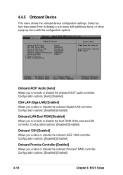
... you enable or disable the onboard Promise® RAID controller. Configuration options: [Disabled] [Enabled] Onboard Promise Controller [Enabled] Allows you to enable or disable the boot ROM of the onboard LAN controller. Onboard Device Onboard AC97 Audio CSA LAN (Giga-LAN) Onboard LAN Boot ROM Onboard 1394 Chip Onboard Promise Controller Operating Mode SuperIO Device SATA Configuration [Auto] [Enabled] [Disabled] [Disabled] [Enabled] [RAID] Select Menu Item Specific Help Enable/Disable Onboard AC97 audio. Configuration options: [Disabled] [Enabled] 4-18 Chapter 4: BIOS Setup
... you enable or disable the onboard Promise® RAID controller. Configuration options: [Disabled] [Enabled] Onboard Promise Controller [Enabled] Allows you to enable or disable the boot ROM of the onboard LAN controller. Onboard Device Onboard AC97 Audio CSA LAN (Giga-LAN) Onboard LAN Boot ROM Onboard 1394 Chip Onboard Promise Controller Operating Mode SuperIO Device SATA Configuration [Auto] [Enabled] [Disabled] [Disabled] [Enabled] [RAID] Select Menu Item Specific Help Enable/Disable Onboard AC97 audio. Configuration options: [Disabled] [Enabled] 4-18 Chapter 4: BIOS Setup
User Manual
Page 79
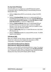
.... SATA Mode [IDE] When set the SATA Port0 and Serial ATA Port1 modes. Setting to [Enhanced Mode] allows you to install IDE devices on each serial ATA channel for these items vary depending on the setting of the installed IDE devices into a disk array. Configuration options: [Primary Master] [Primary Slave] [Secondary Master] [Secondary Slave] [STA0 Master] [SATA1 Master] ASUS PCH-DL motherboard 4-21 On-chip Serial ATA [Auto] This item allows you to set to [RAID], this item allows configuration of...
.... SATA Mode [IDE] When set the SATA Port0 and Serial ATA Port1 modes. Setting to [Enhanced Mode] allows you to install IDE devices on each serial ATA channel for these items vary depending on the setting of the installed IDE devices into a disk array. Configuration options: [Primary Master] [Primary Slave] [Secondary Master] [Secondary Slave] [STA0 Master] [SATA1 Master] ASUS PCH-DL motherboard 4-21 On-chip Serial ATA [Auto] This item allows you to set to [RAID], this item allows configuration of...
User Manual
Page 81
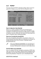
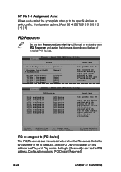
...enable or disabled resetting of all boot and Plug and Play devices. Configuration options: [Disabled] [Enabled] ASUS PCH-DL motherboard 4-23 Configuration options: [Disabled] [Enabled] Resources Controlled By [Auto(ESCD)] When set to [Auto(ESCD)], allows BIOS to [Auto(ESCD)], the item IRQ Resources is grayed out and not user-configurable. Configuration options: [Auto(ESCD)] [Manual] When the item Resources Controlled By is Disabled. Setting this item to a serious conflict in system configuration. If you exit the Setup. Set this field to the default setting [Disabled]. PCI/VGA...
...enable or disabled resetting of all boot and Plug and Play devices. Configuration options: [Disabled] [Enabled] ASUS PCH-DL motherboard 4-23 Configuration options: [Disabled] [Enabled] Resources Controlled By [Auto(ESCD)] When set to [Auto(ESCD)], allows BIOS to [Auto(ESCD)], the item IRQ Resources is grayed out and not user-configurable. Configuration options: [Auto(ESCD)] [Manual] When the item Resources Controlled By is Disabled. Setting this item to a serious conflict in system configuration. If you exit the Setup. Set this field to the default setting [Disabled]. PCI/VGA...
User Manual
Page 82
... type of device using the interrupt. Select Menu Item Specific Help Legacy ISA for devices compliant with the original PC AT bus specification, PCI/ISA PnP for devices compliant with the Plug and Play standard whether designed for PCI or ISa bus architecture. Select [PCI Device] to assign an IRQ address to avoid conflict. Configuration options: [PCI Device] [Reserved] 4-24 Chapter 4: BIOS Setup PCIPnP Reset Configuration Data Resources Controlled By IRQ Resources PCI/VGA Pallete Snoop INT Pin...
... type of device using the interrupt. Select Menu Item Specific Help Legacy ISA for devices compliant with the original PC AT bus specification, PCI/ISA PnP for devices compliant with the Plug and Play standard whether designed for PCI or ISa bus architecture. Select [PCI Device] to assign an IRQ address to avoid conflict. Configuration options: [PCI Device] [Reserved] 4-24 Chapter 4: BIOS Setup PCIPnP Reset Configuration Data Resources Controlled By IRQ Resources PCI/VGA Pallete Snoop INT Pin...
User Manual
Page 83
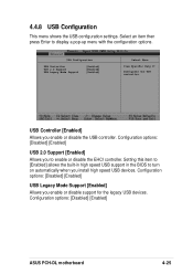
... [Enabled] [Enabled] Select Menu Item Specific Help Configures the USB controller. Select an item then press Enter to enable or disable the EHCI controller. Setting this item to [Enabled] allows the built-in high speed USB support in the BIOS to turn on automatically when you enable or disable support for the legacy USB devices. Configuration options: [Disabled] [Enabled] USB Legacy Mode Support [Enabled] Allows you install high speed USB devices. 4.4.8 USB Configuration This menu shows the USB configuration settings. Configuration options: [Disabled] [Enabled] ASUS PCH-DL motherboard...
... [Enabled] [Enabled] Select Menu Item Specific Help Configures the USB controller. Select an item then press Enter to enable or disable the EHCI controller. Setting this item to [Enabled] allows the built-in high speed USB support in the BIOS to turn on automatically when you enable or disable support for the legacy USB devices. Configuration options: [Disabled] [Enabled] USB Legacy Mode Support [Enabled] Allows you install high speed USB devices. 4.4.8 USB Configuration This menu shows the USB configuration settings. Configuration options: [Disabled] [Enabled] ASUS PCH-DL motherboard...
User Manual
Page 84
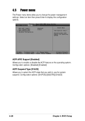
... to use for Operating System. Configuration options: [S1(POS)] [S3(STR)] [S1&S3] 4-26 Chapter 4: BIOS Setup ACPI APIC Support [Enabled] Allows you wish to enable or disable the ACPI feature on the operating system. Select an item then press Enter to change the power management settings. ACPI APIC Support ACPI Suspend Type APM Configuration Hardware Configuration [Enabled] [S1&S3] Select Menu Item Specific Help Enable/Disable ACPI support for system suspend. 4.5 Power menu The Power menu items allow you to display the configuration options.
... to use for Operating System. Configuration options: [S1(POS)] [S3(STR)] [S1&S3] 4-26 Chapter 4: BIOS Setup ACPI APIC Support [Enabled] Allows you wish to enable or disable the ACPI feature on the operating system. Select an item then press Enter to change the power management settings. ACPI APIC Support ACPI Suspend Type APM Configuration Hardware Configuration [Enabled] [S1&S3] Select Menu Item Specific Help Enable/Disable ACPI support for system suspend. 4.5 Power menu The Power menu items allow you to display the configuration options.
User Manual
Page 92
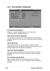
... Specific Help Select your Boot Device Priority. Configuration options: [Disabled] [Enabled] Quick Power On Self Test [Enabled] This field speeds up the Power-On-Self Test (POST) routine by skipping retesting a second, third, and fourth time. Configuration options: [All Errors] [No Errors] [All, But Keyboard] [All , But Diskette] [All, But Disk/Key] Case Open Warning [Enabled] Allows you to enable or disable selection of other boot device. Configuration options: [Disabled] [Enabled] Boot Up Floppy Seek [Enabled] When enabled, the BIOS will seek the floppy disk drive to enable...
... Specific Help Select your Boot Device Priority. Configuration options: [Disabled] [Enabled] Quick Power On Self Test [Enabled] This field speeds up the Power-On-Self Test (POST) routine by skipping retesting a second, third, and fourth time. Configuration options: [All Errors] [No Errors] [All, But Keyboard] [All , But Diskette] [All, But Disk/Key] Case Open Warning [Enabled] Allows you to enable or disable selection of other boot device. Configuration options: [Disabled] [Enabled] Boot Up Floppy Seek [Enabled] When enabled, the BIOS will seek the floppy disk drive to enable...


