User Manual
Page 12
Chapter summary 1.1 Welcome 1-1 1.2 Package contents 1-1 1.3 Special features 1-2 ASUS PCH-DL motherboard
Chapter summary 1.1 Welcome 1-1 1.2 Package contents 1-1 1.3 Special features 1-2 ASUS PCH-DL motherboard
User Manual
Page 13
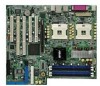
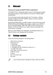
... list below. 1.2 Package contents Check your PCH-DL package for buying the ASUS® PCH-DL motherboard! 1.1 Welcome! Thank you start installing the motherboard, and hardware devices on it another standout in the world of the above items is your retailer. ASUS PCH-DL motherboard 1-1 Supporting 533 MHz FSB, up ... package with Game port S/PDIF Out module I/O shield Bag of extra jumper caps User guide If any of power computing! The ASUS PCH-DL motherboard delivers a host of new features and latest technologies making it , check the items in 604-pin package coupled with dual-...
... list below. 1.2 Package contents Check your PCH-DL package for buying the ASUS® PCH-DL motherboard! 1.1 Welcome! Thank you start installing the motherboard, and hardware devices on it another standout in the world of the above items is your retailer. ASUS PCH-DL motherboard 1-1 Supporting 533 MHz FSB, up ... package with Game port S/PDIF Out module I/O shield Bag of extra jumper caps User guide If any of power computing! The ASUS PCH-DL motherboard delivers a host of new features and latest technologies making it , check the items in 604-pin package coupled with dual-...
User Manual
Page 15
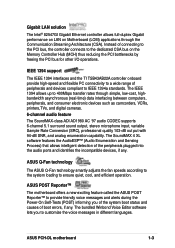
...messages and alerts during the Power-On Self-Tests (POST) informing you to ensure quiet, cool, and efficient operation. ASUS Q-Fan technology The ASUS Q-Fan technology smartly adjusts the fan speeds according to the system loading to customize the voice messages in different languages.... on LAN on the Memory Controller Hub (MCH) thus reducing the PCI bottlenecks by freeing the PCI bus for other I/O operations. ASUS PCH-DL motherboard 1-3 The IEEE 1394 allows up to the dedicated CSA bus on Motherboard (LOM) applications through simple, low-cost, highbandwidth asynchronous...
...messages and alerts during the Power-On Self-Tests (POST) informing you to ensure quiet, cool, and efficient operation. ASUS Q-Fan technology The ASUS Q-Fan technology smartly adjusts the fan speeds according to the system loading to customize the voice messages in different languages.... on LAN on the Memory Controller Hub (MCH) thus reducing the PCI bottlenecks by freeing the PCI bus for other I/O operations. ASUS PCH-DL motherboard 1-3 The IEEE 1394 allows up to the dedicated CSA bus on Motherboard (LOM) applications through simple, low-cost, highbandwidth asynchronous...
User Manual
Page 18
Chapter summary 2.1 Before you proceed 2-1 2.2 Motherboard installation 2-2 2.3 Central Processing Unit (CPU 2-5 2.4 System memory 2-12 2.5 Expansion slots 2-15 2.6 Jumpers 2-18 2.7 Connectors 2-21 ASUS PCH-DL motherboard
Chapter summary 2.1 Before you proceed 2-1 2.2 Motherboard installation 2-2 2.3 Central Processing Unit (CPU 2-5 2.4 System memory 2-12 2.5 Expansion slots 2-15 2.6 Jumpers 2-18 2.7 Connectors 2-21 ASUS PCH-DL motherboard
User Manual
Page 19
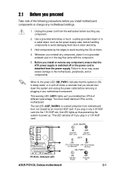
... severe damage to static electricity. 3. AGP_WARN1 ON Incorrect AGP Card OFF Correct AGP Card LED1 PCH-DL PCH-DL Onboard LED ON OFF CPU Type/Voltage CPU Type/Voltage not identical identical SB_PWR1 ON Standby Power OFF Powered Off ASUS PCH-DL Deluxe motherboard 2-1 Unplug the power cord from motherboard burn out caused by the edges to...
... severe damage to static electricity. 3. AGP_WARN1 ON Incorrect AGP Card OFF Correct AGP Card LED1 PCH-DL PCH-DL Onboard LED ON OFF CPU Type/Voltage CPU Type/Voltage not identical identical SB_PWR1 ON Standby Power OFF Powered Off ASUS PCH-DL Deluxe motherboard 2-1 Unplug the power cord from motherboard burn out caused by the edges to...
User Manual
Page 21
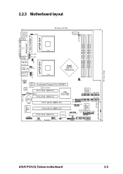
... 4Mbit Flash BIOS SEC_IDE1 PRI_IDE1 PROMISE PDC20378 RAID Controller PRI_RAID1 Super I/O GAME1 PCIX2 (64-bit, 66MHz 3V) PCI3 (32-bit, 33MHz 5V) TI TSB43AB22A SYS_FAN1 PCH-DL IEEE1394_1 J3 SB_PWR1 SATA_RAID1 SATA_RAID2 CLRTC1 CHASSIS1 IDE_LED1 SMB1 PANEL1 FLOPPY1 30.5cm (12in) ASUS PCH-DL Deluxe motherboard 2-3
... 4Mbit Flash BIOS SEC_IDE1 PRI_IDE1 PROMISE PDC20378 RAID Controller PRI_RAID1 Super I/O GAME1 PCIX2 (64-bit, 66MHz 3V) PCI3 (32-bit, 33MHz 5V) TI TSB43AB22A SYS_FAN1 PCH-DL IEEE1394_1 J3 SB_PWR1 SATA_RAID1 SATA_RAID2 CLRTC1 CHASSIS1 IDE_LED1 SMB1 PANEL1 FLOPPY1 30.5cm (12in) ASUS PCH-DL Deluxe motherboard 2-3
User Manual
Page 23
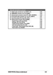
... connector (4-1 pin SPDIF_O1) 2-29 12. Internal audio connectors (4-pin CD1, AUX1, MODEM1) 2-30 14. System warning speaker (4-pin SPKR) 2-32 - Reset switch (2-pin RESET) 2-32 ASUS PCH-DL Deluxe motherboard 2-5 System panel connector (20-pin PANEL) 2-32 - Hard disk activity (2-pin HD_LED) 2-32 - System Power LED (3-pin PLED) 2-32 - GAME/MIDI connector (16...
... connector (4-1 pin SPDIF_O1) 2-29 12. Internal audio connectors (4-pin CD1, AUX1, MODEM1) 2-30 14. System warning speaker (4-pin SPKR) 2-32 - Reset switch (2-pin RESET) 2-32 ASUS PCH-DL Deluxe motherboard 2-5 System panel connector (20-pin PANEL) 2-32 - Hard disk activity (2-pin HD_LED) 2-32 - System Power LED (3-pin PLED) 2-32 - GAME/MIDI connector (16...
User Manual
Page 25
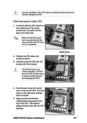
... way, otherwise the CPU does not fit in one correct orientation. Follow these steps to prevent bending the pins and damaging the CPU! Marked Corner 4. ASUS PCH-DL Deluxe motherboard 2-7 DO NOT force the CPU into the socket may bend the pins and severely damage the CPU! Apply the thermal interface material (thermal...
... way, otherwise the CPU does not fit in one correct orientation. Follow these steps to prevent bending the pins and damaging the CPU! Marked Corner 4. ASUS PCH-DL Deluxe motherboard 2-7 DO NOT force the CPU into the socket may bend the pins and severely damage the CPU! Apply the thermal interface material (thermal...
User Manual
Page 27
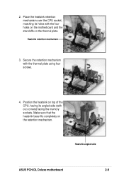
2. Position the heatsink on the retention mechanism. Heatsink angled side ASUS PCH-DL Deluxe motherboard 2-9 Make sure that the heatsink base fits completely on top of the CPU, having its holes with the thermal plate using four screws. 4. Secure the retention mechanism with the four holes on the motherboard and the standoffs on the thermal plate. Place the heatsink retention mechanism over the CPU socket, matching its angled side (with cut corners) facing the memory sockets. Heatsink retention mechanism 3.
2. Position the heatsink on the retention mechanism. Heatsink angled side ASUS PCH-DL Deluxe motherboard 2-9 Make sure that the heatsink base fits completely on top of the CPU, having its holes with the thermal plate using four screws. 4. Secure the retention mechanism with the four holes on the motherboard and the standoffs on the thermal plate. Place the heatsink retention mechanism over the CPU socket, matching its angled side (with cut corners) facing the memory sockets. Heatsink retention mechanism 3.
User Manual
Page 29
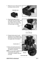
... side rails of the air tunnel by twisting it back and forth. Detachable cover 8. Align the two pegs on its sides. Hook 9. Groove (inner side) ASUS PCH-DL motherboard 2-11 Press the module down until the four hooks on the air tunnel snap on the air tunnel with pegs Curved corners 10. Corners...
... side rails of the air tunnel by twisting it back and forth. Detachable cover 8. Align the two pegs on its sides. Hook 9. Groove (inner side) ASUS PCH-DL motherboard 2-11 Press the module down until the four hooks on the air tunnel snap on the air tunnel with pegs Curved corners 10. Corners...
User Manual
Page 31
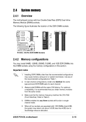
... location of the recommended configurations in this section. DIMMs installed into the DIMM sockets using the memory configurations in Table 1. 2. ASUS PCH-DL motherboard 2-13 DIMM_B2 DIMM_A2 DIMM_B1 80 Pins DIMM_A1 104 Pins PCH-DL PCH-DL 184-Pin DDR DIMM Sockets 2.4.2 Memory configurations You may cause memory sizing error or system boot failure. Installing DDR DIMMs...
... location of the recommended configurations in this section. DIMMs installed into the DIMM sockets using the memory configurations in Table 1. 2. ASUS PCH-DL motherboard 2-13 DIMM_B2 DIMM_A2 DIMM_B1 80 Pins DIMM_A1 104 Pins PCH-DL PCH-DL 184-Pin DDR DIMM Sockets 2.4.2 Memory configurations You may cause memory sizing error or system boot failure. Installing DDR DIMMs...
User Manual
Page 33
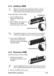
... may cause severe damage to remove a DIMM. 1. Support the DIMM lightly with extra force. 2. DDR DIMM notch Unlocked Retaining Clip A DDR DIMM is properly seated. ASUS PCH-DL motherboard 2-15
... may cause severe damage to remove a DIMM. 1. Support the DIMM lightly with extra force. 2. DDR DIMM notch Unlocked Retaining Clip A DDR DIMM is properly seated. ASUS PCH-DL motherboard 2-15
User Manual
Page 35
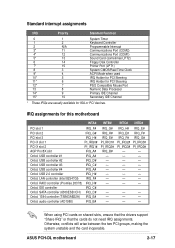
... (AD1980) IRQ_B# IRQ_G# IRQ_H# IRQ_E# PI_IRQ1# PI_IRQ2# IRQ_B# - - - Otherwise, conflicts will arise between the two PCI groups, making the system unstable and the card inoperable. ASUS PCH-DL motherboard 2-17 USB controller #4 IRQ_A# Onbd. SATA controller (6300ESB ICH) IRQ_C# Onbd. 1394 controller (TSB43AB22A) IRQ_E# Onbd. USB controller #3 IRQ_C# Onbd. IRQ_H# IRQ_E# IRQ_E# IRQ_F...
... (AD1980) IRQ_B# IRQ_G# IRQ_H# IRQ_E# PI_IRQ1# PI_IRQ2# IRQ_B# - - - Otherwise, conflicts will arise between the two PCI groups, making the system unstable and the card inoperable. ASUS PCH-DL motherboard 2-17 USB controller #4 IRQ_A# Onbd. SATA controller (6300ESB ICH) IRQ_C# Onbd. 1394 controller (TSB43AB22A) IRQ_E# Onbd. USB controller #3 IRQ_C# Onbd. IRQ_H# IRQ_E# IRQ_E# IRQ_F...
User Manual
Page 37
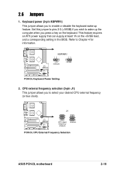
... supply that can supply at least 1A on the keyboard. KBPWR1 12 23 +5V (Default) +5VSB PCH-DL PCH-DL Keyboard Power Setting 2. Refer to wake up feature. J1 1 2 3 4 CPU select frequency (Default) 3 4 5 6 100MHz PCH-DL PCH-DL CPU External Frequency Selection ASUS PCH-DL motherboard 2-19 CPU external frequency selection (3-pin J1) This jumper allows you wish to Chapter 4 for...
... supply that can supply at least 1A on the keyboard. KBPWR1 12 23 +5V (Default) +5VSB PCH-DL PCH-DL Keyboard Power Setting 2. Refer to wake up feature. J1 1 2 3 4 CPU select frequency (Default) 3 4 5 6 100MHz PCH-DL PCH-DL CPU External Frequency Selection ASUS PCH-DL motherboard 2-19 CPU external frequency selection (3-pin J1) This jumper allows you wish to Chapter 4 for...
User Manual
Page 39
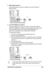
...power cord and turn ON the computer. 6. ASUS PCH-DL motherboard 2-21 Clear RTC RAM (3-pin CLRTC1) This jumper allows you enable or disable the Promise PDC20378 RAID controller. Keep the cap on CLRTC jumper default position. Removing the cap will cause system boot failure! PCH-DL PCH-DL Clear RTC RAM CLRTC1 12 23 Normal (...CMOS. Re-install the battery. 5. Hold down the key during the boot process and enter BIOS setup to pins 2-3. J2 12 23 Enable (Default) PCH-DL PCH-DL Promise Raid Chip Setting Disable 6. RAID enable (3-pin J2) This jumper allows you to pins 1-2. 4.
...power cord and turn ON the computer. 6. ASUS PCH-DL motherboard 2-21 Clear RTC RAM (3-pin CLRTC1) This jumper allows you enable or disable the Promise PDC20378 RAID controller. Keep the cap on CLRTC jumper default position. Removing the cap will cause system boot failure! PCH-DL PCH-DL Clear RTC RAM CLRTC1 12 23 Normal (...CMOS. Re-install the battery. 5. Hold down the key during the boot process and enter BIOS setup to pins 2-3. J2 12 23 Enable (Default) PCH-DL PCH-DL Promise Raid Chip Setting Disable 6. RAID enable (3-pin J2) This jumper allows you to pins 1-2. 4.
User Manual
Page 41
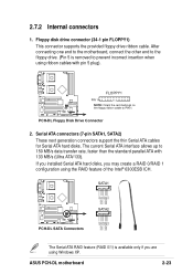
...other end to the floppy drive. (Pin 5 is available only if you may create a RAID 0/RAID 1 configuration using Windows XP. ASUS PCH-DL motherboard 2-23 Floppy disk drive connector (34-1 pin FLOPPY1) This connector supports the provided floppy drive ribbon cable. The current Serial ATA... interface allows up to PIN 1. SATA1 GND RSATA_TXP1 RSATA_TXN1 GND RSATA_RXN1 RSATA_RXP1 GND PCH-DL PCH-DL SATA Connectors GND RSATA_TXP2 RSATA_TXN2 GND RSATA_RXN2 RSATA_RXP2 GND SATA2 The Serial ATA RAID feature (RAID 0/1) is removed to prevent ...
...other end to the floppy drive. (Pin 5 is available only if you may create a RAID 0/RAID 1 configuration using Windows XP. ASUS PCH-DL motherboard 2-23 Floppy disk drive connector (34-1 pin FLOPPY1) This connector supports the provided floppy drive ribbon cable. The current Serial ATA... interface allows up to PIN 1. SATA1 GND RSATA_TXP1 RSATA_TXN1 GND RSATA_RXN1 RSATA_RXP1 GND PCH-DL PCH-DL SATA Connectors GND RSATA_TXP2 RSATA_TXN2 GND RSATA_RXN2 RSATA_RXP2 GND SATA2 The Serial ATA RAID feature (RAID 0/1) is removed to prevent ...
User Manual
Page 43
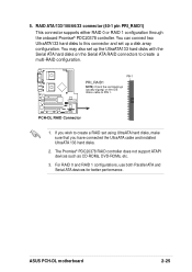
...may also set up the UltraATA133 hard disks with the Serial ATA hard disks on the IDE ribbon cable to create a multi-RAID configuration. PCH-DL PCH-DL RAID Connector 1. 5. You can connect two UltraATA133 hard disks to create a RAID set using UltraATA hard disks, make sure that you wish... ATAPI devices such as CD-ROMs, DVD-ROMs, etc. 3. If you have connected the UltraATA cable and installed UltraATA 133 hard disks. 2. ASUS PCH-DL motherboard 2-25 RAID ATA/133/100/66/33 connector (40-1 pin PRI_RAID1) This connector supports either RAID 0 or RAID 1 configuration through the ...
...may also set up the UltraATA133 hard disks with the Serial ATA hard disks on the IDE ribbon cable to create a multi-RAID configuration. PCH-DL PCH-DL RAID Connector 1. 5. You can connect two UltraATA133 hard disks to create a RAID set using UltraATA hard disks, make sure that you wish... ATAPI devices such as CD-ROMs, DVD-ROMs, etc. 3. If you have connected the UltraATA cable and installed UltraATA 133 hard disks. 2. ASUS PCH-DL motherboard 2-25 RAID ATA/133/100/66/33 connector (40-1 pin PRI_RAID1) This connector supports either RAID 0 or RAID 1 configuration through the ...
User Manual
Page 45
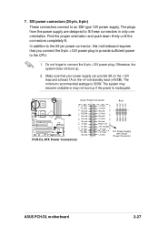
... +5 Volts Ground +5 Volts Ground Power OK +5V Standby +12 Volts +12 Volts +3 Volts GND GND For Power Supply with 20-pin Power Connector GND GND ASUS PCH-DL motherboard 2-27 Find the proper orientation and push down firmly until the connectors completely fit. Make sure that you connect the 8-pin +12V power plug...
... +5 Volts Ground +5 Volts Ground Power OK +5V Standby +12 Volts +12 Volts +3 Volts GND GND For Power Supply with 20-pin Power Connector GND GND ASUS PCH-DL motherboard 2-27 Find the proper orientation and push down firmly until the connectors completely fit. Make sure that you connect the 8-pin +12V power plug...
User Manual
Page 47
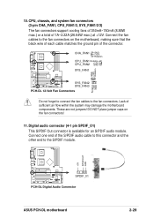
... matches the ground pin of the S/PDIF audio cable to this connector and the other end to the S/PDIF module. +5V SPDIFOUT GND SPDIF_01 PCH-DL PCH-DL Digital Audio Connector ASUS PCH-DL motherboard 2-29 These are not jumpers! 10. Connect the fan cables to the fan connectors. CHA_FAN1 GND +12V Rotation CPU_FAN1 Rotation CPU_FAN2 +12V...
... matches the ground pin of the S/PDIF audio cable to this connector and the other end to the S/PDIF module. +5V SPDIFOUT GND SPDIF_01 PCH-DL PCH-DL Digital Audio Connector ASUS PCH-DL motherboard 2-29 These are not jumpers! 10. Connect the fan cables to the fan connectors. CHA_FAN1 GND +12V Rotation CPU_FAN1 Rotation CPU_FAN2 +12V...
User Manual
Page 49
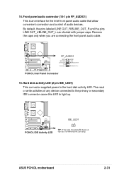
PCH-DL PCH-DL IDE Activity LED IDE_LED1 -+ TIP: If the case-mounted LED does not light up . 14. By default, the pins labeled LINE OUT_R/BLINE_OUT_R and the ... device connected to the primary or secondary IDE connector cause this LED to the hard disk activity LED. ASUS PCH-DL motherboard 2-31 FP_AUDIO1 MIC2 MICPWR Line out_R NC Line out_L AGND +5VA BLINE_OUT_R BLINE_OUT_L PCH-DL PCH-DL Intel Panel Connector 15. Hard disk activity LED (2-pin IDE_LED1) This connector supplied power to light up , try...
PCH-DL PCH-DL IDE Activity LED IDE_LED1 -+ TIP: If the case-mounted LED does not light up . 14. By default, the pins labeled LINE OUT_R/BLINE_OUT_R and the ... device connected to the primary or secondary IDE connector cause this LED to the hard disk activity LED. ASUS PCH-DL motherboard 2-31 FP_AUDIO1 MIC2 MICPWR Line out_R NC Line out_L AGND +5VA BLINE_OUT_R BLINE_OUT_L PCH-DL PCH-DL Intel Panel Connector 15. Hard disk activity LED (2-pin IDE_LED1) This connector supplied power to light up , try...


