User Manual
Page 4
...Primary IDE Slave 4-10 4.3.3 Secondary IDE Master 4-10 4.3.4 Secondary IDE Slave 4-10 4.3.5 Third IDE Master 4-11 4.3.6 Fourth IDE Master 4-11 4.4 Advanced menu 4-12 4.4.1 Advanced BIOS Features 4-12 4.4.2 CPU Configuration 4-13 4.4.3 Memory Configuration 4-14 4.4.4 Chipset 4-15 4.4.5 Onboard Device 4-18 4.4.6 Speech Configuration 4-22 4.4.7 PCIPnP 4-23 4.4.8 USB Configuration 4-25 ... Priority 4-33 4.6.3 Removable Device Priority 4-33 4.6.4 Boot Settings Configuration 4-34 4.6.5 Security 4-35 4.7 Exit menu 4-37 Appendix: Reference information A.1 PCH-DL block diagram A-1 iv
...Primary IDE Slave 4-10 4.3.3 Secondary IDE Master 4-10 4.3.4 Secondary IDE Slave 4-10 4.3.5 Third IDE Master 4-11 4.3.6 Fourth IDE Master 4-11 4.4 Advanced menu 4-12 4.4.1 Advanced BIOS Features 4-12 4.4.2 CPU Configuration 4-13 4.4.3 Memory Configuration 4-14 4.4.4 Chipset 4-15 4.4.5 Onboard Device 4-18 4.4.6 Speech Configuration 4-22 4.4.7 PCIPnP 4-23 4.4.8 USB Configuration 4-25 ... Priority 4-33 4.6.3 Removable Device Priority 4-33 4.6.4 Boot Settings Configuration 4-34 4.6.5 Security 4-35 4.7 Exit menu 4-37 Appendix: Reference information A.1 PCH-DL block diagram A-1 iv
User Manual
Page 7
... when installing system components. How this guide This user guide contains the information you may refer to change system settings through the BIOS Setup menus. vii Detailed descriptions of the PCH-DL motherboard. It includes brief descriptions of the special attributes of the switches, jumpers, and connectors on the motherboard. • Chapter 3: Powering...
... when installing system components. How this guide This user guide contains the information you may refer to change system settings through the BIOS Setup menus. vii Detailed descriptions of the PCH-DL motherboard. It includes brief descriptions of the special attributes of the switches, jumpers, and connectors on the motherboard. • Chapter 3: Powering...
User Manual
Page 10
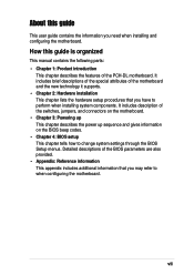
... ATX form factor: 12in x 10.5in (30.5cm x 26.7cm) Device drivers Management software System utilities ASUS contact information *Specifications are subject to change without notice. x PCH-DL specifications summary Internal I/O BIOS features Industry standard Manageability Power requirement Form Factor Support CD contents CPU/SYSTEM/CHASSIS fan connectors 24-pin/8-pin...1 x IEEE 1394 connector GAME/MIDI connector S/PDIF Out connector CD/AUX/Modem connectors Front panel audio connector 4Mb Flash ROM, Phoenix-Award BIOS, PnP, DMI2.0, WfM2.0, SM BIOS2.3 PCI 2.2, PCI-X 1.0a, USB 2.0 WfM 2.0.
... ATX form factor: 12in x 10.5in (30.5cm x 26.7cm) Device drivers Management software System utilities ASUS contact information *Specifications are subject to change without notice. x PCH-DL specifications summary Internal I/O BIOS features Industry standard Manageability Power requirement Form Factor Support CD contents CPU/SYSTEM/CHASSIS fan connectors 24-pin/8-pin...1 x IEEE 1394 connector GAME/MIDI connector S/PDIF Out connector CD/AUX/Modem connectors Front panel audio connector 4Mb Flash ROM, Phoenix-Award BIOS, PnP, DMI2.0, WfM2.0, SM BIOS2.3 PCI 2.2, PCI-X 1.0a, USB 2.0 WfM 2.0.
User Manual
Page 16
C.P.R. (CPU Parameter Recall) The C.P.R. feature of the motherboard BIOS allows automatic re-setting to the BIOS default settings in case the system hangs due to open the system chassis and clear the RTC data. eliminates the need to overclocking...utility or boot from a floppy disk. Simply shut down and reboot the system, and BIOS automatically restores the CPU default setting for each parameter. 1-4 Chapter 1: Product introduction ASUS EZ Flash BIOS With the ASUS EZ Flash, you can easily update the system BIOS even before loading the operating system. No need to overclocking.
C.P.R. (CPU Parameter Recall) The C.P.R. feature of the motherboard BIOS allows automatic re-setting to the BIOS default settings in case the system hangs due to open the system chassis and clear the RTC data. eliminates the need to overclocking...utility or boot from a floppy disk. Simply shut down and reboot the system, and BIOS automatically restores the CPU default setting for each parameter. 1-4 Chapter 1: Product introduction ASUS EZ Flash BIOS With the ASUS EZ Flash, you can easily update the system BIOS even before loading the operating system. No need to overclocking.
User Manual
Page 21
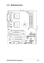
... PCIX1 (64-bit, 66MHz 3V) SATA1 SATA2 SYS_FAN3 SYS_FAN2 SPDIF_OUT 4Mbit Flash BIOS SEC_IDE1 PRI_IDE1 PROMISE PDC20378 RAID Controller PRI_RAID1 Super I/O GAME1 PCIX2 (64-bit, 66MHz 3V) PCI3 (32-bit, 33MHz 5V) TI TSB43AB22A SYS_FAN1 PCH-DL IEEE1394_1 J3 SB_PWR1 SATA_RAID1 SATA_RAID2 CLRTC1 CHASSIS1 IDE_LED1 SMB1 PANEL1 FLOPPY1 30.5cm (12in) ASUS PCH-DL Deluxe motherboard 2-3
... PCIX1 (64-bit, 66MHz 3V) SATA1 SATA2 SYS_FAN3 SYS_FAN2 SPDIF_OUT 4Mbit Flash BIOS SEC_IDE1 PRI_IDE1 PROMISE PDC20378 RAID Controller PRI_RAID1 Super I/O GAME1 PCIX2 (64-bit, 66MHz 3V) PCI3 (32-bit, 33MHz 5V) TI TSB43AB22A SYS_FAN1 PCH-DL IEEE1394_1 J3 SB_PWR1 SATA_RAID1 SATA_RAID2 CLRTC1 CHASSIS1 IDE_LED1 SMB1 PANEL1 FLOPPY1 30.5cm (12in) ASUS PCH-DL Deluxe motherboard 2-3
User Manual
Page 34
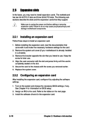
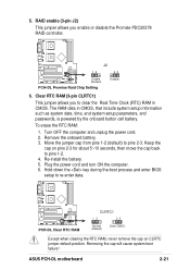
Keep the screw for the expansion card. 2-16 Chapter 2: Hardware information Refer to the tables on the system and change the necessary BIOS settings, if any. Replace the system cover. 2.5.2 Configuring an expansion card After installing the expansion card, configure it and make the ...card. 2. Turn on the next page. 3. Make sure to the card. Remove the system unit cover (if your motherboard is completely seated on BIOS setup. 2. Before installing the expansion card, read the documentation that came with the screw you may cause you intend to the chassis with it by...
Keep the screw for the expansion card. 2-16 Chapter 2: Hardware information Refer to the tables on the system and change the necessary BIOS settings, if any. Replace the system cover. 2.5.2 Configuring an expansion card After installing the expansion card, configure it and make the ...card. 2. Turn on the next page. 3. Make sure to the card. Remove the system unit cover (if your motherboard is completely seated on BIOS setup. 2. Before installing the expansion card, read the documentation that came with the screw you may cause you intend to the chassis with it by...
User Manual
Page 37
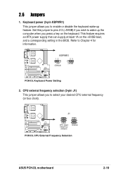
..., and a corresponding setting in the BIOS. Refer to select your desired CPU external frequency (or bus clock). Set this jumper to pins 2-3 (+5VSB) if you to Chapter 4 for information. KBPWR1 12 23 +5V (Default) +5VSB PCH-DL PCH-DL Keyboard Power Setting 2. J1 1 2 3 4 CPU select frequency (Default) 3 4 5 6 100MHz PCH-DL PCH-DL CPU External Frequency Selection ASUS PCH-DL motherboard 2-19 2.6 Jumpers 1.
..., and a corresponding setting in the BIOS. Refer to select your desired CPU external frequency (or bus clock). Set this jumper to pins 2-3 (+5VSB) if you to Chapter 4 for information. KBPWR1 12 23 +5V (Default) +5VSB PCH-DL PCH-DL Keyboard Power Setting 2. J1 1 2 3 4 CPU select frequency (Default) 3 4 5 6 100MHz PCH-DL PCH-DL CPU External Frequency Selection ASUS PCH-DL motherboard 2-19 2.6 Jumpers 1.
User Manual
Page 39
... about 5~10 seconds, then move the cap back to pins 2-3. The RAM data in CMOS. J2 12 23 Enable (Default) PCH-DL PCH-DL Promise Raid Chip Setting Disable 6. ASUS PCH-DL motherboard 2-21 Keep the cap on CLRTC jumper default position. Removing the cap will cause system boot failure! Remove the onboard battery.... the RTC RAM: 1. Turn OFF the computer and unplug the power cord. 2. Hold down the key during the boot process and enter BIOS setup to clear the Real Time Clock (RTC) RAM in CMOS, that include system setup information such as system date, time, and system...
... about 5~10 seconds, then move the cap back to pins 2-3. The RAM data in CMOS. J2 12 23 Enable (Default) PCH-DL PCH-DL Promise Raid Chip Setting Disable 6. ASUS PCH-DL motherboard 2-21 Keep the cap on CLRTC jumper default position. Removing the cap will cause system boot failure! Remove the onboard battery.... the RTC RAM: 1. Turn OFF the computer and unplug the power cord. 2. Hold down the key during the boot process and enter BIOS setup to clear the Real Time Clock (RTC) RAM in CMOS, that include system setup information such as system date, time, and system...
User Manual
Page 44
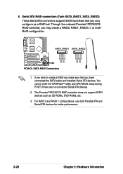
.... You cannot enter the SATARaid™ utility and SATA BIOS setup during POST if there are no connected Serial ATA devices. 2. For RAID 0 and RAID 1 configurations, use both Parallel ATA and Serial ATA devices for better performance. 2-26 Chapter 2: Hardware information SATA_RAID1 SATA_RAID2 PCH-DL PCH-DL SATA RAID Connectors 1. GND RSATA_TXP1 RSATA_TXN1 GND RSATA_RXN1...
.... You cannot enter the SATARaid™ utility and SATA BIOS setup during POST if there are no connected Serial ATA devices. 2. For RAID 0 and RAID 1 configurations, use both Parallel ATA and Serial ATA devices for better performance. 2-26 Chapter 2: Hardware information SATA_RAID1 SATA_RAID2 PCH-DL PCH-DL SATA RAID Connectors 1. GND RSATA_TXP1 RSATA_TXN1 GND RSATA_RXN1...
User Manual
Page 50
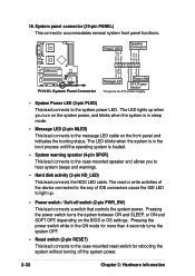
...) This lead connects the HDD LED cable. 16. Power LED Speaker Connector PLED+ LAN_LINK PLED+5V HD_LED+ HD_LEDSpeaker LAN_ACT +5VSB MLED PWR Ground Reset Ground PCH-DL PCH-DL System Panel Connector Message LED Reset SW ATX Power Switch* * Requires an ATX power supply. • System Power LED (3-pin PLED) This lead connects to...
...) This lead connects the HDD LED cable. 16. Power LED Speaker Connector PLED+ LAN_LINK PLED+5V HD_LED+ HD_LEDSpeaker LAN_ACT +5VSB MLED PWR Ground Reset Ground PCH-DL PCH-DL System Panel Connector Message LED Reset SW ATX Power Switch* * Requires an ATX power supply. • System Power LED (3-pin PLED) This lead connects to...
User Manual
Page 51
Chapter 3 This chapter describes the power up Powering up sequence and gives information on the BIOS beep codes.
Chapter 3 This chapter describes the power up Powering up sequence and gives information on the BIOS beep codes.
User Manual
Page 53
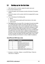
... if it has a "power standby" feature, the monitor LED may have failed a power-on . Follow the instructions in the following order: a. ASUS PCH-DL motherboard 3-1 Connect the power cord to a power outlet that all the connections, replace the system case cover. 2. Turn on the screen. External SCSI... devices (starting with a surge protector. 5. Award/Phoenix BIOS beep codes No. For SSI-type power supplies, the system LED lights up . of the system chassis. 4. Be sure that is equipped ...
... if it has a "power standby" feature, the monitor LED may have failed a power-on . Follow the instructions in the following order: a. ASUS PCH-DL motherboard 3-1 Connect the power cord to a power outlet that all the connections, replace the system case cover. 2. Turn on the screen. External SCSI... devices (starting with a surge protector. 5. Award/Phoenix BIOS beep codes No. For SSI-type power supplies, the system LED lights up . of the system chassis. 4. Be sure that is equipped ...
User Manual
Page 54
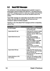
... System failed CPU test System failed memory test System failed VGA test System failed due to the recommended settings. 3-2 Chapter 3: Powering up See the "ASUS contact information." • Install 184-pin unbuffered PC3200/2700/2100 DIMMs into the DIMM sockets. • Check if the DIMMs on the DIMM sockets ...are properly installed. • Make sure that your CPU settings in BIOS and make sure you only set to CPU over-clocking Action • Install an Intel® Xeon™ Processor into the CPU socket. •...
... System failed CPU test System failed memory test System failed VGA test System failed due to the recommended settings. 3-2 Chapter 3: Powering up See the "ASUS contact information." • Install 184-pin unbuffered PC3200/2700/2100 DIMMs into the DIMM sockets. • Check if the DIMMs on the DIMM sockets ...are properly installed. • Make sure that your CPU settings in BIOS and make sure you only set to CPU over-clocking Action • Install an Intel® Xeon™ Processor into the CPU socket. •...
User Manual
Page 56
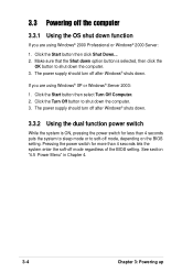
...button is ON, pressing the power switch for more than 4 seconds puts the system to sleep mode or to soft-off mode, depending on the BIOS setting. Click the Turn Off button to shut down . The power supply should turn off after Windows® shuts down the computer. 3. See ...Professional or Windows® 2000 Server: 1. Pressing the power switch for less than 4 seconds lets the system enter the soft-off mode regardless of the BIOS setting. Click the Start button then click Shut Down... 2. 3.3 Powering off the computer 3.3.1 Using the OS shut down the computer. 3. Click the ...
...button is ON, pressing the power switch for more than 4 seconds puts the system to sleep mode or to soft-off mode, depending on the BIOS setting. Click the Turn Off button to shut down . The power supply should turn off after Windows® shuts down the computer. 3. See ...Professional or Windows® 2000 Server: 1. Pressing the power switch for less than 4 seconds lets the system enter the soft-off mode regardless of the BIOS setting. Click the Start button then click Shut Down... 2. 3.3 Powering off the computer 3.3.1 Using the OS shut down the computer. 3. Click the ...
User Manual
Page 57
Detailed descriptions of the BIOS parameters are also provided. BIOS setup Chapter 4 This chapter tells how to change system settings through the BIOS Setup menus.
Detailed descriptions of the BIOS parameters are also provided. BIOS setup Chapter 4 This chapter tells how to change system settings through the BIOS Setup menus.
User Manual
Page 58
Chapter summary 4.1 Managing and updating your BIOS 4-1 4.2 BIOS Setup program 4-3 4.3 Main menu 4-6 4.4 Advanced menu 4-12 4.5 Power menu 4-26 4.6 Boot menu 4-32 4.7 Exit menu 4-37 ASUS PCH-DL motherboard
Chapter summary 4.1 Managing and updating your BIOS 4-1 4.2 BIOS Setup program 4-3 4.3 Main menu 4-6 4.4 Advanced menu 4-12 4.5 Power menu 4-26 4.6 Boot menu 4-32 4.7 Exit menu 4-37 ASUS PCH-DL motherboard
User Manual
Page 59
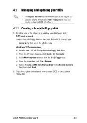
...new 1.44 MB floppy disk in the Format Options field, then click Start. 2. b. Copy the original (or the latest) motherboard BIOS to create a bootable floppy disk. From the Windows desktop, click Start > My Computer. From the Menu bar, click File > ...BIOS • The original BIOS file for this motherboard is in the support CD. • Copy the original BIOS to a bootable floppy disk in case you need to restore the BIOS in the future. 4.1.1 Creating a bootable floppy disk 1. e. At the DOS prompt, type: format a: /s, then press the key Windows® XP environment a. d. ASUS PCH-DL...
...new 1.44 MB floppy disk in the Format Options field, then click Start. 2. b. Copy the original (or the latest) motherboard BIOS to create a bootable floppy disk. From the Windows desktop, click Start > My Computer. From the Menu bar, click File > ...BIOS • The original BIOS file for this motherboard is in the support CD. • Copy the original BIOS to a bootable floppy disk in case you need to restore the BIOS in the future. 4.1.1 Creating a bootable floppy disk 1. e. At the DOS prompt, type: format a: /s, then press the key Windows® XP environment a. d. ASUS PCH-DL...
User Manual
Page 60
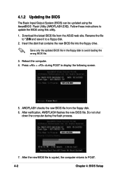
AWDFLASH checks the new BIOS file from the ASUS web site. Download the latest BIOS file from the floppy disk. 6. After the new BIOS file is copied, the computer returns to avoid loading the wrong BIOS file. 3. Save only the updated BIOS file in the floppy disk to POST. 4-2 Chapter 4: BIOS Setup After verification, AWDFLASH flashes the new...
AWDFLASH checks the new BIOS file from the ASUS web site. Download the latest BIOS file from the floppy disk. 6. After the new BIOS file is copied, the computer returns to avoid loading the wrong BIOS file. 3. Save only the updated BIOS file in the floppy disk to POST. 4-2 Chapter 4: BIOS Setup After verification, AWDFLASH flashes the new...
User Manual
Page 61
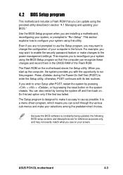
... chassis. The Flash ROM on your system, or prompted to run this last option only if the first two failed. Because the BIOS software is designed to make your BIOS." ASUS PCH-DL motherboard 4-3 For example, you may not exactly match what you are installing a motherboard, reconfiguring your screen. Press during the Power-On Self...
... chassis. The Flash ROM on your system, or prompted to run this last option only if the first two failed. Because the BIOS software is designed to make your BIOS." ASUS PCH-DL motherboard 4-3 For example, you may not exactly match what you are installing a motherboard, reconfiguring your screen. Press during the Power-On Self...
User Manual
Page 62
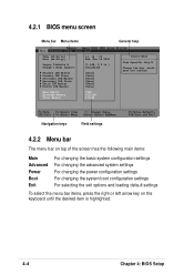
... default settings To select the menu bar items, press the right or left arrow key on the keyboard until the desired item is highlighted. 4-4 Chapter 4: BIOS Setup 4.2.1 BIOS menu screen Menu bar Menu items General help Time (hh:mm:ss) Date (mm:dd:yy) Legacy Diskette A Floppy 3 Mode Support Primary IDE Master...
... default settings To select the menu bar items, press the right or left arrow key on the keyboard until the desired item is highlighted. 4-4 Chapter 4: BIOS Setup 4.2.1 BIOS menu screen Menu bar Menu items General help Time (hh:mm:ss) Date (mm:dd:yy) Legacy Diskette A Floppy 3 Mode Support Primary IDE Master...


