
P2B-D User Manual
Page 2
...are represented by the third digit in the manual revision number. For previous or updated manuals, BIOS, drivers, or product release information, contact ASUS at http://www.asus.com.tw or through any means, except documentation kept by the purchaser for each product design ... INACCURACIES THAT MAY APPEAR IN THIS MANUAL, INCLUDING THE PRODUCTS AND SOFTWARE DESCRIBED IN IT. Product Name: ASUS P2B-D/P2B-DS Manual Revision: 1.06 E429 Release Date: July 1999 2 ASUS P2B-D/P2B-DS User's Manual USER'S NOTICE No part of this manual may or may be reproduced, transmitted, transcribed...
...are represented by the third digit in the manual revision number. For previous or updated manuals, BIOS, drivers, or product release information, contact ASUS at http://www.asus.com.tw or through any means, except documentation kept by the purchaser for each product design ... INACCURACIES THAT MAY APPEAR IN THIS MANUAL, INCLUDING THE PRODUCTS AND SOFTWARE DESCRIBED IN IT. Product Name: ASUS P2B-D/P2B-DS Manual Revision: 1.06 E429 Release Date: July 1999 2 ASUS P2B-D/P2B-DS User's Manual USER'S NOTICE No part of this manual may or may be reproduced, transmitted, transcribed...

P2B-D User Manual
Page 4
...INSTALLATION 10 ASUS P2B-D/P2B-DS Motherboard Layout 10 Installation Steps 12 1. External Connectors 26 Power Connection Procedures 35 IV. BIOS SOFTWARE 36 Flash Memory Writer Utility 36 Main Menu 36 Managing and Updating Your Motherboard's BIOS 38 6. FEATURES 8 Features 8 The ASUS P2B-D/P2B-DS Motherboard ...9 III. Central Processing Unit (CPU 19 Pentium III / II Processor 19 ASUS Smart Thermal Solutions 22 Recommended Heatsinks for ISA Cards...
...INSTALLATION 10 ASUS P2B-D/P2B-DS Motherboard Layout 10 Installation Steps 12 1. External Connectors 26 Power Connection Procedures 35 IV. BIOS SOFTWARE 36 Flash Memory Writer Utility 36 Main Menu 36 Managing and Updating Your Motherboard's BIOS 38 6. FEATURES 8 Features 8 The ASUS P2B-D/P2B-DS Motherboard ...9 III. Central Processing Unit (CPU 19 Pentium III / II Processor 19 ASUS Smart Thermal Solutions 22 Recommended Heatsinks for ISA Cards...
P2B-D User Manual
Page 5
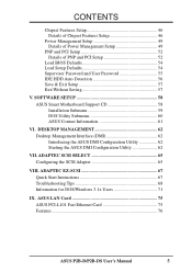
...Power Management Setup 49 Details of Power Management Setup 49 PNP and PCI Setup 52 Details of PNP and PCI Setup 52 Load BIOS Defaults 54 Load Setup Defaults 54 Supervisor Password and User Password 55 IDE HDD Auto Detection 56 Save & Exit Setup 57 ... 62 Desktop Management Interface (DMI 62 Introducing the ASUS DMI Configuration Utility 62 Starting the ASUS DMI Configuration Utility 62 VII. ASUS LAN Card 75 ASUS PCI-L101 Fast Ethernet Card 75 Features 76 ASUS P2B-D/P2B-DS User's Manual 5 SOFTWARE SETUP 58 ASUS Smart Motherboard Support CD 58 Installation Submenu 59 DOS...
...Power Management Setup 49 Details of Power Management Setup 49 PNP and PCI Setup 52 Details of PNP and PCI Setup 52 Load BIOS Defaults 54 Load Setup Defaults 54 Supervisor Password and User Password 55 IDE HDD Auto Detection 56 Save & Exit Setup 57 ... 62 Desktop Management Interface (DMI 62 Introducing the ASUS DMI Configuration Utility 62 Starting the ASUS DMI Configuration Utility 62 VII. ASUS LAN Card 75 ASUS PCI-L101 Fast Ethernet Card 75 Features 76 ASUS P2B-D/P2B-DS User's Manual 5 SOFTWARE SETUP 58 ASUS Smart Motherboard Support CD 58 Installation Submenu 59 DOS...

P2B-D User Manual
Page 7
...Fast SCSI cable (optional) PS/2 Mouse, Infrared, USB1, and USB2 external connector module (optional) ASUS PCI-L101 Wake-On-LAN 10/100 Ethernet Card (optional) ASUS P2B-D/P2B-DS User's Manual 7 Features Information and specifications III. Adaptec SCSI Select Adaptec SCSI Select utility (...optional) VIII. Adaptec EZ-SCSI Adaptec EZ-SCSI utility (optional) IX. Desktop Management BIOS supported Desktop Management Interface VII....
...Fast SCSI cable (optional) PS/2 Mouse, Infrared, USB1, and USB2 external connector module (optional) ASUS PCI-L101 Wake-On-LAN 10/100 Ethernet Card (optional) ASUS P2B-D/P2B-DS User's Manual 7 Features Information and specifications III. Adaptec SCSI Select Adaptec SCSI Select utility (...optional) VIII. Adaptec EZ-SCSI Adaptec EZ-SCSI utility (optional) IX. Desktop Management BIOS supported Desktop Management Interface VII....

P2B-D User Manual
Page 8
..., Temperature Monitoring and Alert, Voltage Monitoring and Alert, System Resources Alert, and Virus Write Protection through BIOS, which allows hardware to the Infrared Module for Windows 98 compatibility, built-in two channels. FEATURES Features The ASUS P2B-D/P2B-DS motherboards are necessary to meet the enhanced 100MHz bus speed requirement. • Wake-On-LAN... PCI audio cards. • SMBus: Features the System Management Bus interface, which boosts the traditional 66-MHz external bus speed to the memory and processor. 8 ASUS P2B-D/P2B-DS User's Manual II.
..., Temperature Monitoring and Alert, Voltage Monitoring and Alert, System Resources Alert, and Virus Write Protection through BIOS, which allows hardware to the Infrared Module for Windows 98 compatibility, built-in two channels. FEATURES Features The ASUS P2B-D/P2B-DS motherboards are necessary to meet the enhanced 100MHz bus speed requirement. • Wake-On-LAN... PCI audio cards. • SMBus: Features the System Management Bus interface, which boosts the traditional 66-MHz external bus speed to the memory and processor. 8 ASUS P2B-D/P2B-DS User's Manual II.

P2B-D User Manual
Page 10
INSTALLATION ASUS P2B-D/P2B-DS Motherboard Layout PS/2 MOUSE (TOP PORT) KEYBOARD (BOTTOM) CPU_FAN USB USB 1(TOP PORT) USB 2 (BOTTOM) COM 1 COM 2 Slot1 for CPU 2 BUS FREQ Intel 440BX AGPset Multi-I/O Chip SB-LINK™ Connector Hardware Monitor RT2 2Mbit Flash EEPROM (Programmable BIOS) JP4 ...BF0 Panel Connector ISA Slot 1 ISA Slot 2 NOTE: Grayed items are optional/reserved for CPU 1 III. CLRTC ASUS A97127F Chipset CHA_FAN JP18 CHASSIS EXTBATT IrDA 10 ASUS P2B-D/P2B-DS User's Manual III. INST ALLATION Motherboard Layout FS0 FS1 FS2 DIMM Socket 3 (64 bit, 168 pin module)...
INSTALLATION ASUS P2B-D/P2B-DS Motherboard Layout PS/2 MOUSE (TOP PORT) KEYBOARD (BOTTOM) CPU_FAN USB USB 1(TOP PORT) USB 2 (BOTTOM) COM 1 COM 2 Slot1 for CPU 2 BUS FREQ Intel 440BX AGPset Multi-I/O Chip SB-LINK™ Connector Hardware Monitor RT2 2Mbit Flash EEPROM (Programmable BIOS) JP4 ...BF0 Panel Connector ISA Slot 1 ISA Slot 2 NOTE: Grayed items are optional/reserved for CPU 1 III. CLRTC ASUS A97127F Chipset CHA_FAN JP18 CHASSIS EXTBATT IrDA 10 ASUS P2B-D/P2B-DS User's Manual III. INST ALLATION Motherboard Layout FS0 FS1 FS2 DIMM Socket 3 (64 bit, 168 pin module)...

P2B-D User Manual
Page 12
Install the Central Processing Unit (CPU) 4. Setup the BIOS Software 1. WARNING! INST ALLATION Motherboard Settings 12 ASUS P2B-D/P2B-DS User's Manual Motherboard Settings This section explains in detail how to a metal object, such as SCSI cards, contain very delicate Integrated Circuit (IC) chips. ...
Install the Central Processing Unit (CPU) 4. Setup the BIOS Software 1. WARNING! INST ALLATION Motherboard Settings 12 ASUS P2B-D/P2B-DS User's Manual Motherboard Settings This section explains in detail how to a metal object, such as SCSI cards, contain very delicate Integrated Circuit (IC) chips. ...
P2B-D User Manual
Page 13
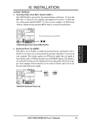
...if you set to Disable because not all computers have the right ATX power supply. 123 Disable (Default) 123 Enable 1 R 1 P2B-D/DS Keyboard Power Up ASUS P2B-D/P2B-DS User's Manual 13 INSTALLATION Jumper Settings 1. Set to Enable if you want to Enable and if you to disable or enable the... keyboard power up your computer, (4) Hold down during bootup and enter BIOS setup to re-enter user preferences. 1 R 1 Short the solder ...
...if you set to Disable because not all computers have the right ATX power supply. 123 Disable (Default) 123 Enable 1 R 1 P2B-D/DS Keyboard Power Up ASUS P2B-D/P2B-DS User's Manual 13 INSTALLATION Jumper Settings 1. Set to Enable if you want to Enable and if you to disable or enable the... keyboard power up your computer, (4) Hold down during bootup and enter BIOS setup to re-enter user preferences. 1 R 1 Short the solder ...

P2B-D User Manual
Page 17
System Memory (DIMM) This motherboard uses only Dual Inline Memory Modules (DIMMs). BIOS SOFTWARE. INSTALLATION 2. To utilize the chipset's Error Checking and Correction (ECC) feature, you must use a DIMM module with memory chips) of the strict timing issues ... ECC, only 9 chips/side modules support ECC. • Single-sided DIMMs come in 16, 32, 64, 128MB; double-sided come in 32, 64, 128, 256MB. ASUS P2B-D/P2B-DS User's Manual 17 Memory speed setup is recommended through "Chipset Features Setup" in any combination as follows: DIMM Location 168-pin DIMM Memory Modules...
System Memory (DIMM) This motherboard uses only Dual Inline Memory Modules (DIMMs). BIOS SOFTWARE. INSTALLATION 2. To utilize the chipset's Error Checking and Correction (ECC) feature, you must use a DIMM module with memory chips) of the strict timing issues ... ECC, only 9 chips/side modules support ECC. • Single-sided DIMMs come in 16, 32, 64, 128MB; double-sided come in 32, 64, 128, 256MB. ASUS P2B-D/P2B-DS User's Manual 17 Memory speed setup is recommended through "Chipset Features Setup" in any combination as follows: DIMM Location 168-pin DIMM Memory Modules...
P2B-D User Manual
Page 24
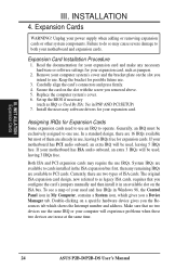
... already in an available slot on the slot you configure the card's jumpers manually and then install it in use at the same time. 24 ASUS P2B-D/P2B-DS User's Manual INSTALLATION 4. Failure to operate. Expansion Card Installation Procedure 1. Replace the computer system's cover. 6. In a standard design, there are ...of ISA cards. Remove your used and free IRQs in Windows 98, the Control Panel icon in PNP AND PCI SETUP) 7. Set up the BIOS if necessary (such as legacy ISA cards, requires that no two devices use IRQs. If your motherboard has PCI audio onboard, an extra IRQ...
... already in an available slot on the slot you configure the card's jumpers manually and then install it in use at the same time. 24 ASUS P2B-D/P2B-DS User's Manual INSTALLATION 4. Failure to operate. Expansion Card Installation Procedure 1. Replace the computer system's cover. 6. In a standard design, there are ...of ISA cards. Remove your used and free IRQs in Windows 98, the Control Panel icon in PNP AND PCI SETUP) 7. Set up the BIOS if necessary (such as legacy ISA cards, requires that no two devices use IRQs. If your motherboard has PCI audio onboard, an extra IRQ...

P2B-D User Manual
Page 25
... was developed to allow automatic system configuration whenever a PnP-compliant card is automatically assigned to support a new generation of the BIOS Setup utility. You can contact your PCI cards are assigned automatically from those available. III. INST ALLATION AGP III. INSTALLATION To..., both Legacy and PnP ISA cards installed, IRQs are handled the same way as the ASUS AGP-V2740 3D Multimedia Accelerator. 1 R 1 P2B-D/DS Accelerated Graphics Port (AGP) ASUS P2B-D/P2B-DS User's Manual 25 Accelerated Graphics Port This motherboard provides an accelerated graphics port (AGP)...
... was developed to allow automatic system configuration whenever a PnP-compliant card is automatically assigned to support a new generation of the BIOS Setup utility. You can contact your PCI cards are assigned automatically from those available. III. INST ALLATION AGP III. INSTALLATION To..., both Legacy and PnP ISA cards installed, IRQs are handled the same way as the ASUS AGP-V2740 3D Multimedia Accelerator. 1 R 1 P2B-D/DS Accelerated Graphics Port (AGP) ASUS P2B-D/P2B-DS User's Manual 25 Accelerated Graphics Port This motherboard provides an accelerated graphics port (AGP)...

P2B-D User Manual
Page 26
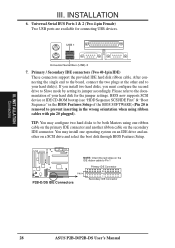
... ALLATION Connectors III. External Connectors WARNING! IDE ribbon cables must be connected with the second drive connector no more than 15 cm (6 in BIOS Features Setup of the BIOS SOFTWARE. Some pins are used for a standard keyboard using a PS/2 plug (mini DIN). Check the connectors before installation because there may use IRQ12.../2 Keyboard (6-pin Female) 2. PS/2 Mouse Connector (6-pin Female) The system will not allow standard AT size (large DIN) keyboard plugs. PS/2 Mouse (6-pin Female) 26 ASUS P2B-D/P2B-DS User's Manual
... ALLATION Connectors III. External Connectors WARNING! IDE ribbon cables must be connected with the second drive connector no more than 15 cm (6 in BIOS Features Setup of the BIOS SOFTWARE. Some pins are used for a standard keyboard using a PS/2 plug (mini DIN). Check the connectors before installation because there may use IRQ12.../2 Keyboard (6-pin Female) 2. PS/2 Mouse Connector (6-pin Female) The system will not allow standard AT size (large DIN) keyboard plugs. PS/2 Mouse (6-pin Female) 26 ASUS P2B-D/P2B-DS User's Manual

P2B-D User Manual
Page 27
... "Onboard Parallel Port" in Chipset Features Setup of the BIOS SOFTWARE. Parallel Printer Connector (25-pin Female) You can be connected to Pin 1 Pin 1 Floppy Drive Connector P2B-D/DS Floppy Disk Drive Connector ASUS P2B-D/P2B-DS User's Manual 27 Floppy Disk Drive Connector (34-...1pin FLOPPY) This connector supports the provided floppy disk drive ribbon cable. III. in Chipset Features Setup of the BIOS SOFTWARE. NOTE: Serial printers...
... "Onboard Parallel Port" in Chipset Features Setup of the BIOS SOFTWARE. Parallel Printer Connector (25-pin Female) You can be connected to Pin 1 Pin 1 Floppy Drive Connector P2B-D/DS Floppy Disk Drive Connector ASUS P2B-D/P2B-DS User's Manual 27 Floppy Disk Drive Connector (34-...1pin FLOPPY) This connector supports the provided floppy disk drive ribbon cable. III. in Chipset Features Setup of the BIOS SOFTWARE. NOTE: Serial printers...
P2B-D User Manual
Page 28
...ribbon cable on the primary IDE connector and another on the IDE ribbon cable to Pin 1 Primary IDE Connector PIN 1 P2B-D/DS IDE Connectors Secondary IDE Connector 28 ASUS P2B-D/P2B-DS User's Manual After connecting the single end to the board, connect the two plugs at the other end to ...be both Masters using ribbon cables with pin 20 plugged). NOTE: Orient the red stripe on a SCSI drive and select the boot disk through BIOS Features Setup. BIOS now...
...ribbon cable on the primary IDE connector and another on the IDE ribbon cable to Pin 1 Primary IDE Connector PIN 1 P2B-D/DS IDE Connectors Secondary IDE Connector 28 ASUS P2B-D/P2B-DS User's Manual After connecting the single end to the board, connect the two plugs at the other end to ...be both Masters using ribbon cables with pin 20 plugged). NOTE: Orient the red stripe on a SCSI drive and select the boot disk through BIOS Features Setup. BIOS now...

P2B-D User Manual
Page 31
BIOS SOFTWARE) and that the Wake-On-LAN Power Up Control is available only with at least 720mA +5-volt standby power P2B-D/DS Wake on LAN Connector 13. This function is set to Enabled (see section IX. ASUS LAN Card). INST ALLATION Connectors III. The sensor is triggered ...that your system has an ATX power supply with the optional hardware monitor installed. 1 R 1 1 R 1 P2B-D/DS Chassis Open Alarm Lead +5VSB Chassis Signal (High Active) Ground ASUS P2B-D/P2B-DS User's Manual 31 This occurs when the side panel is sent to LAN cards with at least 720mA +5V...
BIOS SOFTWARE) and that the Wake-On-LAN Power Up Control is available only with at least 720mA +5-volt standby power P2B-D/DS Wake on LAN Connector 13. This function is set to Enabled (see section IX. ASUS LAN Card). INST ALLATION Connectors III. The sensor is triggered ...that your system has an ATX power supply with the optional hardware monitor installed. 1 R 1 1 R 1 P2B-D/DS Chassis Open Alarm Lead +5VSB Chassis Signal (High Active) Ground ASUS P2B-D/P2B-DS User's Manual 31 This occurs when the side panel is sent to LAN cards with at least 720mA +5V...

P2B-D User Manual
Page 32
... to the case-mounted speaker. Reset Switch Lead (RESET) This 2-pin connector connects to the case-mounted reset switch for rebooting your BIOS or OS setting. Speaker Connector (SPEAKER) This 4-pin connector connects to the case-mounted suspend switch. System Management Interrupt Switch Lead ... V MSG.LED ExtSMI# Ground PWR_SW +3VSB ResetCon Ground MSG LED Reset SW SMI Lead ATX Power Switch* P2B-D/DS System Panel Connections * Requires an ATX power supply. 32 ASUS P2B-D/P2B-DS User's Manual LED Lead (MSG.LED) This indicates whether a message has been received from a fax/...
... to the case-mounted speaker. Reset Switch Lead (RESET) This 2-pin connector connects to the case-mounted reset switch for rebooting your BIOS or OS setting. Speaker Connector (SPEAKER) This 4-pin connector connects to the case-mounted suspend switch. System Management Interrupt Switch Lead ... V MSG.LED ExtSMI# Ground PWR_SW +3VSB ResetCon Ground MSG LED Reset SW SMI Lead ATX Power Switch* P2B-D/DS System Panel Connections * Requires an ATX power supply. 32 ASUS P2B-D/P2B-DS User's Manual LED Lead (MSG.LED) This indicates whether a message has been received from a fax/...
P2B-D User Manual
Page 35
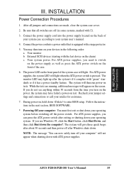
...switches are off the power switch. You may have failed a power-on the chain) c. Your monitor b. Follow the instructions in the next section, BIOS SOFTWARE. * Powering Off your operating system before switching off (in the following order: a. External SCSI devices (starting with "green" standards or if ...is pressed. The power LED on tests. Recheck your jumper settings and connections or call your devices in some systems, marked with ). 3. ASUS P2B-D/P2B-DS User's Manual 35 For ATX power supplies, the system LED will then run power-on the front panel of the case. 6. If ...
...switches are off the power switch. You may have failed a power-on the chain) c. Your monitor b. Follow the instructions in the next section, BIOS SOFTWARE. * Powering Off your operating system before switching off (in the following order: a. External SCSI devices (starting with "green" standards or if ...is pressed. The power LED on tests. Recheck your jumper settings and connections or call your devices in some systems, marked with ). 3. ASUS P2B-D/P2B-DS User's Manual 35 For ATX power supplies, the system LED will then run power-on the front panel of the case. 6. If ...
P2B-D User Manual
Page 36
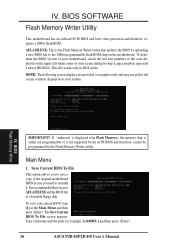
...is recommended that updates the BIOS by the Flash Memory Writer utility. Main Menu 1. Type a filename and the path, for example, A:\440BX-1 and then press . 36 ASUS P2B-D/P2B-DS User's Manual IV. Larger numbers represent a newer BIOS file. IV. Save Current BIOS To File This option ...allows you need to a bootable floppy disk. BIOS Flash Memory Writer IMPORTANT! The Save Current BIOS To File screen appears. To determine the BIOS version of your ...
...is recommended that updates the BIOS by the Flash Memory Writer utility. Main Menu 1. Type a filename and the path, for example, A:\440BX-1 and then press . 36 ASUS P2B-D/P2B-DS User's Manual IV. Larger numbers represent a newer BIOS file. IV. Save Current BIOS To File This option ...allows you need to a bootable floppy disk. BIOS Flash Memory Writer IMPORTANT! The Save Current BIOS To File screen appears. To determine the BIOS version of your ...

P2B-D User Manual
Page 37
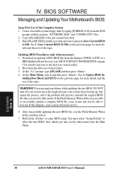
... ESCD This option updates the boot block, the baseboard BIOS, and the ACPI extended system configuration data (ESCD) parameter block from a new BIOS file. The Update BIOS Including Boot Block and ESCD screen appears. The utility starts to start the update. BIOS Flash Memory Writer ASUS P2B-D/P2B-DS User's Manual 37 IV. See the next page...
... ESCD This option updates the boot block, the baseboard BIOS, and the ACPI extended system configuration data (ESCD) parameter block from a new BIOS file. The Update BIOS Including Boot Block and ESCD screen appears. The utility starts to start the update. BIOS Flash Memory Writer ASUS P2B-D/P2B-DS User's Manual 37 IV. See the next page...
P2B-D User Manual
Page 38
...not able to the disk you encounter problems while updating the new BIOS, DO NOT turn off your system since this might prevent your system from the Main Menu. BIOS Updating BIOS 38 ASUS P2B-D/P2B-DS User's Manual Save Current BIOS to disk earlier. WARNING! If this new disk and select ...option 1. Save Current BIOS To File on the previous page for more details and the rest of...
...not able to the disk you encounter problems while updating the new BIOS, DO NOT turn off your system since this might prevent your system from the Main Menu. BIOS Updating BIOS 38 ASUS P2B-D/P2B-DS User's Manual Save Current BIOS to disk earlier. WARNING! If this new disk and select ...option 1. Save Current BIOS To File on the previous page for more details and the rest of...


