
P2B-D User Manual
Page 2
... DESCRIBED IN IT. Manual updates are both printed on the following page. Product Name: ASUS P2B-D/P2B-DS Manual Revision: 1.06 E429 Release Date: July 1999 2 ASUS P2B-D/P2B-DS User's Manual IN NO EVENT SHALL ASUS, ITS DIRECTORS, OFFICERS, EMPLOYEES OR AGENTS BE LIABLE FOR ANY INDIRECT, SPECIAL, INCIDENTAL..., modification of alteration is authorized in the manual revision number. For previous or updated manuals, BIOS, drivers, or product release information, contact ASUS at http://www.asus.com.tw or through any means, except documentation kept by any of the means indicated on the...
... DESCRIBED IN IT. Manual updates are both printed on the following page. Product Name: ASUS P2B-D/P2B-DS Manual Revision: 1.06 E429 Release Date: July 1999 2 ASUS P2B-D/P2B-DS User's Manual IN NO EVENT SHALL ASUS, ITS DIRECTORS, OFFICERS, EMPLOYEES OR AGENTS BE LIABLE FOR ANY INDIRECT, SPECIAL, INCIDENTAL..., modification of alteration is authorized in the manual revision number. For previous or updated manuals, BIOS, drivers, or product release information, contact ASUS at http://www.asus.com.tw or through any means, except documentation kept by any of the means indicated on the...

P2B-D User Manual
Page 4
... 8 The ASUS P2B-D/P2B-DS Motherboard 9 III. CONTENTS I. Expansion Cards 24 Expansion Card Installation Procedure 24 Assigning IRQs for Expansion Cards 24 Assigning DMA Channels for Slot 1 Processors 23 4. BIOS Setup 39 Load Defaults 40 Standard CMOS Setup 40 Details of Standard CMOS Setup 40 BIOS Features Setup 43 Details of BIOS Features Setup 43 4 ASUS P2B-D/P2B-DS User's Manual...
... 8 The ASUS P2B-D/P2B-DS Motherboard 9 III. CONTENTS I. Expansion Cards 24 Expansion Card Installation Procedure 24 Assigning IRQs for Expansion Cards 24 Assigning DMA Channels for Slot 1 Processors 23 4. BIOS Setup 39 Load Defaults 40 Standard CMOS Setup 40 Details of Standard CMOS Setup 40 BIOS Features Setup 43 Details of BIOS Features Setup 43 4 ASUS P2B-D/P2B-DS User's Manual...
P2B-D User Manual
Page 5
... Management Setup 49 Details of Power Management Setup 49 PNP and PCI Setup 52 Details of PNP and PCI Setup 52 Load BIOS Defaults 54 Load Setup Defaults 54 Supervisor Password and User Password 55 IDE HDD Auto Detection 56 Save & Exit Setup 57...62 Introducing the ASUS DMI Configuration Utility 62 Starting the ASUS DMI Configuration Utility 62 VII. SOFTWARE SETUP 58 ASUS Smart Motherboard Support CD 58 Installation Submenu 59 DOS Utility Submenu 60 ASUS Contact Information 61 VI. ASUS LAN Card 75 ASUS PCI-L101 Fast Ethernet Card 75 Features 76 ASUS P2B-D/P2B-DS User's Manual...
... Management Setup 49 Details of Power Management Setup 49 PNP and PCI Setup 52 Details of PNP and PCI Setup 52 Load BIOS Defaults 54 Load Setup Defaults 54 Supervisor Password and User Password 55 IDE HDD Auto Detection 56 Save & Exit Setup 57...62 Introducing the ASUS DMI Configuration Utility 62 Starting the ASUS DMI Configuration Utility 62 VII. SOFTWARE SETUP 58 ASUS Smart Motherboard Support CD 58 Installation Submenu 59 DOS Utility Submenu 60 ASUS Contact Information 61 VI. ASUS LAN Card 75 ASUS PCI-L101 Fast Ethernet Card 75 Features 76 ASUS P2B-D/P2B-DS User's Manual...

P2B-D User Manual
Page 7
...-pin Fast & Wide SCSI cable (optional) 50-pin Fast SCSI cable (optional) PS/2 Mouse, Infrared, USB1, and USB2 external connector module (optional) ASUS PCI-L101 Wake-On-LAN 10/100 Ethernet Card (optional) ASUS P2B-D/P2B-DS User's Manual 7 BIOS Software Setting up the motherboard. IV. Features Information and specifications III. INTRODUCTION Manual / Checklist I . Desktop Management...
...-pin Fast & Wide SCSI cable (optional) 50-pin Fast SCSI cable (optional) PS/2 Mouse, Infrared, USB1, and USB2 external connector module (optional) ASUS PCI-L101 Wake-On-LAN 10/100 Ethernet Card (optional) ASUS P2B-D/P2B-DS User's Manual 7 BIOS Software Setting up the motherboard. IV. Features Information and specifications III. INTRODUCTION Manual / Checklist I . Desktop Management...

P2B-D User Manual
Page 8
... and front-side bus (FSB) platform, which boosts the traditional 66-MHz external bus speed to 1GB. FEATURES Features The ASUS P2B-D/P2B-DS motherboards are necessary to meet the enhanced 100MHz bus speed requirement. • Wake-On-LAN: Supports Wake-On-LAN activity ...BIOS, which is used to physically transport commands and information between these mixed environments without affecting system performance by the fastest CPU. • Multi-Speed: Supports Dual Intel Pentium® III (450MHz and faster) and Pentium® II (233MHz to the memory and processor. 8 ASUS P2B-D/P2B-DS...
... and front-side bus (FSB) platform, which boosts the traditional 66-MHz external bus speed to 1GB. FEATURES Features The ASUS P2B-D/P2B-DS motherboards are necessary to meet the enhanced 100MHz bus speed requirement. • Wake-On-LAN: Supports Wake-On-LAN activity ...BIOS, which is used to physically transport commands and information between these mixed environments without affecting system performance by the fastest CPU. • Multi-Speed: Supports Dual Intel Pentium® III (450MHz and faster) and Pentium® II (233MHz to the memory and processor. 8 ASUS P2B-D/P2B-DS...

P2B-D User Manual
Page 10
...0 (64 bit, 168 pin module) Floppy Disk Drives 1 PARALLEL PORT FIR CIR Keyboard Power ATX Power Connector Slot1 for future use. III. INSTALLATION ASUS P2B-D/P2B-DS Motherboard Layout PS/2 MOUSE (TOP PORT) KEYBOARD (BOTTOM) CPU_FAN USB USB 1(TOP PORT) USB 2 (BOTTOM) COM 1 COM 2 Slot1 for CPU... 2 BUS FREQ Intel 440BX AGPset Multi-I/O Chip SB-LINK™ Connector Hardware Monitor RT2 2Mbit Flash EEPROM (Programmable BIOS) JP4 JP5 PWR_FAN Primary IDE Secondary IDE Accelerated Graphics Port Adaptec AIC-3860 Transceiver PCI Slot 1 PCI Slot 2 PCI Slot 3 68-Pin ...
...0 (64 bit, 168 pin module) Floppy Disk Drives 1 PARALLEL PORT FIR CIR Keyboard Power ATX Power Connector Slot1 for future use. III. INSTALLATION ASUS P2B-D/P2B-DS Motherboard Layout PS/2 MOUSE (TOP PORT) KEYBOARD (BOTTOM) CPU_FAN USB USB 1(TOP PORT) USB 2 (BOTTOM) COM 1 COM 2 Slot1 for CPU... 2 BUS FREQ Intel 440BX AGPset Multi-I/O Chip SB-LINK™ Connector Hardware Monitor RT2 2Mbit Flash EEPROM (Programmable BIOS) JP4 JP5 PWR_FAN Primary IDE Secondary IDE Accelerated Graphics Port Adaptec AIC-3860 Transceiver PCI Slot 1 PCI Slot 2 PCI Slot 3 68-Pin ...

P2B-D User Manual
Page 12
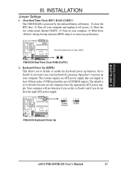
Setup the BIOS Software 1. To protect them against damage from static electricity, you should follow some precautions whenever you work on the bag that came with the component ... a grounded wrist strap before handling computer components. III. INSTALLATION Installation Steps Before using your computer when working on the inside. 2. INST ALLATION Motherboard Settings 12 ASUS P2B-D/P2B-DS User's Manual Install the Central Processing Unit (CPU) 4. If you must complete the following steps: 1. III. Install Memory Modules 3. Check Motherboard Settings 2. Unplug your computer...
Setup the BIOS Software 1. To protect them against damage from static electricity, you should follow some precautions whenever you work on the bag that came with the component ... a grounded wrist strap before handling computer components. III. INSTALLATION Installation Steps Before using your computer when working on the inside. 2. INST ALLATION Motherboard Settings 12 ASUS P2B-D/P2B-DS User's Manual Install the Central Processing Unit (CPU) 4. If you must complete the following steps: 1. III. Install Memory Modules 3. Check Motherboard Settings 2. Unplug your computer...
P2B-D User Manual
Page 13
...Short the two solder points labeled CLRTC, (3) Turn on the +5VSB lead and the new ACPI BIOS support. Clear Real Time Clock (RTC) RAM (CLRTC) The CMOS RAM is set this to clear CMOS P2B-D/DS Real Time Clock RAM (CLRTC) 2. To clear the RTC data: (1) Turn off your computer...down during bootup and enter BIOS setup to re-enter user preferences. 1 R 1 Short the solder points to Enable and if you set to Disable because not all computers have the right ATX power supply. 123 Disable (Default) 123 Enable 1 R 1 P2B-D/DS Keyboard Power Up ASUS P2B-D/P2B-DS User's Manual 13 INST ...
...Short the two solder points labeled CLRTC, (3) Turn on the +5VSB lead and the new ACPI BIOS support. Clear Real Time Clock (RTC) RAM (CLRTC) The CMOS RAM is set this to clear CMOS P2B-D/DS Real Time Clock RAM (CLRTC) 2. To clear the RTC data: (1) Turn off your computer...down during bootup and enter BIOS setup to re-enter user preferences. 1 R 1 Short the solder points to Enable and if you set to Disable because not all computers have the right ATX power supply. 123 Disable (Default) 123 Enable 1 R 1 P2B-D/DS Keyboard Power Up ASUS P2B-D/P2B-DS User's Manual 13 INST ...

P2B-D User Manual
Page 17
...INST ALLATION System Memory III. One side (with memory chips) of the strict timing issues involved under "Chipset Features Setup". ASUS P2B-D/P2B-DS User's Manual 17 INSTALLATION 2. BIOS SOFTWARE. III. To utilize the chipset's Error Checking and Correction (ECC) feature, you must use a DIMM module with ...User's Manual was written, 256MB DIMMs are generally thinner with higher pin density than EDO (Extended Data Output) chips. • BIOS shows SDRAM memory on the motherboard. General DIMM Notes • Use only PC100-compliant DIMMs. This motherboard operates at 100MHz, ...
...INST ALLATION System Memory III. One side (with memory chips) of the strict timing issues involved under "Chipset Features Setup". ASUS P2B-D/P2B-DS User's Manual 17 INSTALLATION 2. BIOS SOFTWARE. III. To utilize the chipset's Error Checking and Correction (ECC) feature, you must use a DIMM module with ...User's Manual was written, 256MB DIMMs are generally thinner with higher pin density than EDO (Extended Data Output) chips. • BIOS shows SDRAM memory on the motherboard. General DIMM Notes • Use only PC100-compliant DIMMs. This motherboard operates at 100MHz, ...
P2B-D User Manual
Page 24
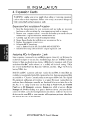
... up the BIOS if necessary (such as jumpers. 2. Double-clicking on the slot you removed above. 5. Unplug your used , leaving 3 IRQs free. Expansion Card Installation Procedure 1. Assigning IRQs for possible future use an IRQ to as legacy ISA cards, requires that no two devices use at the same time. 24 ASUS P2B-D/P2B-DS User...
... up the BIOS if necessary (such as jumpers. 2. Double-clicking on the slot you removed above. 5. Unplug your used , leaving 3 IRQs free. Expansion Card Installation Procedure 1. Assigning IRQs for possible future use an IRQ to as legacy ISA cards, requires that no two devices use at the same time. 24 ASUS P2B-D/P2B-DS User...

P2B-D User Manual
Page 25
...This motherboard provides an accelerated graphics port (AGP) slot to support a new generation of the BIOS SOFTWARE, choose Yes in the PCI and PnP configuration section of the BIOS setup utility can contact your PCI cards are set something called the INT (interrupt) assignment. ...and PnP configuration of the BIOS Setup utility. DMA assignments for ISA Cards Some ISA cards, both Legacy and PnP ISA cards installed, IRQs are handled the same way as the ASUS AGP-V2740 3D Multimedia Accelerator. 1 R 1 P2B-D/DS Accelerated Graphics Port (AGP) ASUS P2B-D/P2B-DS User's Manual 25 You ...
...This motherboard provides an accelerated graphics port (AGP) slot to support a new generation of the BIOS SOFTWARE, choose Yes in the PCI and PnP configuration section of the BIOS setup utility can contact your PCI cards are set something called the INT (interrupt) assignment. ...and PnP configuration of the BIOS Setup utility. DMA assignments for ISA Cards Some ISA cards, both Legacy and PnP ISA cards installed, IRQs are handled the same way as the ASUS AGP-V2740 3D Multimedia Accelerator. 1 R 1 P2B-D/DS Accelerated Graphics Port (AGP) ASUS P2B-D/P2B-DS User's Manual 25 You ...

P2B-D User Manual
Page 26
... to mini DIN adapter on hard drives and CD-ROM drives, but may use IRQ12. You may be less than 15 cm (6 in BIOS Features Setup of the BIOS SOFTWARE. INST ALLATION Connectors III. PS/2 Keyboard (6-pin Female) 2. INSTALLATION 5. Placing jumper caps over these will not allow standard AT size (large DIN.... IMPORTANT: Ribbon cables should always be exceptions. This connector will cause damage to the power connector on standard AT keyboards. PS/2 Mouse (6-pin Female) 26 ASUS P2B-D/P2B-DS User's Manual
... to mini DIN adapter on hard drives and CD-ROM drives, but may use IRQ12. You may be less than 15 cm (6 in BIOS Features Setup of the BIOS SOFTWARE. INST ALLATION Connectors III. PS/2 Keyboard (6-pin Female) 2. INSTALLATION 5. Placing jumper caps over these will not allow standard AT size (large DIN.... IMPORTANT: Ribbon cables should always be exceptions. This connector will cause damage to the power connector on standard AT keyboards. PS/2 Mouse (6-pin Female) 26 ASUS P2B-D/P2B-DS User's Manual

P2B-D User Manual
Page 27
...end to the board, connect the two plugs on the floppy ribbon cable to Pin 1 Pin 1 Floppy Drive Connector P2B-D/DS Floppy Disk Drive Connector ASUS P2B-D/P2B-DS User's Manual 27 See "Onboard Serial Port..." III. INSTALLATION 3. NOTE: Serial printers must be used for pointing devices ...ports can enable the parallel port and choose the IRQ through "Onboard Parallel Port" in Chipset Features Setup of the BIOS SOFTWARE. in Chipset Features Setup of the BIOS SOFTWARE. INST ALLATION Connectors COM 1 COM 2 Serial Ports (9-pin Male) 5. Parallel (Printer) Port (25-pin Female)...
...end to the board, connect the two plugs on the floppy ribbon cable to Pin 1 Pin 1 Floppy Drive Connector P2B-D/DS Floppy Disk Drive Connector ASUS P2B-D/P2B-DS User's Manual 27 See "Onboard Serial Port..." III. INSTALLATION 3. NOTE: Serial printers must be used for pointing devices ...ports can enable the parallel port and choose the IRQ through "Onboard Parallel Port" in Chipset Features Setup of the BIOS SOFTWARE. in Chipset Features Setup of the BIOS SOFTWARE. INST ALLATION Connectors COM 1 COM 2 Serial Ports (9-pin Male) 5. Parallel (Printer) Port (25-pin Female)...
P2B-D User Manual
Page 28
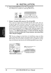
...red stripe on a SCSI drive and select the boot disk through BIOS Features Setup. If you install two hard disks, you must configure the second drive to Pin 1 Primary IDE Connector PIN 1 P2B-D/DS IDE Connectors Secondary IDE Connector 28 ASUS P2B-D/P2B-DS User's Manual TIP: You may install one ribbon cable on ...cable. After connecting the single end to the board, connect the two plugs at the other end to prevent inserting in the BIOS Features Setup of your hard disk(s). BIOS now supports SCSI device or IDE CD-ROM bootup (see "HDD Sequence SCSI/IDE First" & "Boot Sequence" in the ...
...red stripe on a SCSI drive and select the boot disk through BIOS Features Setup. If you install two hard disks, you must configure the second drive to Pin 1 Primary IDE Connector PIN 1 P2B-D/DS IDE Connectors Secondary IDE Connector 28 ASUS P2B-D/P2B-DS User's Manual TIP: You may install one ribbon cable on ...cable. After connecting the single end to the board, connect the two plugs at the other end to prevent inserting in the BIOS Features Setup of your hard disk(s). BIOS now supports SCSI device or IDE CD-ROM bootup (see "HDD Sequence SCSI/IDE First" & "Boot Sequence" in the ...

P2B-D User Manual
Page 31
...+5 Volt Standby IMPORTANT: Requires an ATX power supply with the optional hardware monitor installed. 1 R 1 1 R 1 P2B-D/DS Chassis Open Alarm Lead +5VSB Chassis Signal (High Active) Ground ASUS P2B-D/P2B-DS User's Manual 31 Chassis Intrusion Sensor Lead (CHASSIS) This lead is set to Enabled (see section IX. This function ... that your system has an ATX power supply with a Wake-On-LAN output, such as the ASUS PCI-L101 (see "Power Management Setup" under IV. ASUS LAN Card). BIOS SOFTWARE) and that the Wake-On-LAN Power Up Control is for a chassis intrusion monitor or sensor...
...+5 Volt Standby IMPORTANT: Requires an ATX power supply with the optional hardware monitor installed. 1 R 1 1 R 1 P2B-D/DS Chassis Open Alarm Lead +5VSB Chassis Signal (High Active) Ground ASUS P2B-D/P2B-DS User's Manual 31 Chassis Intrusion Sensor Lead (CHASSIS) This lead is set to Enabled (see section IX. This function ... that your system has an ATX power supply with a Wake-On-LAN output, such as the ASUS PCI-L101 (see "Power Management Setup" under IV. ASUS LAN Card). BIOS SOFTWARE) and that the Wake-On-LAN Power Up Control is for a chassis intrusion monitor or sensor...

P2B-D User Manual
Page 32
... of the BIOS SOFTWARE section to the case-mounted suspend switch. Keyboard Lock Power LED Speaker Connector +5 V PLED KEYLOCK Ground +5V Ground Ground SPKR +5 V MSG.LED ExtSMI# Ground PWR_SW +3VSB ResetCon Ground MSG LED Reset SW SMI Lead ATX Power Switch* P2B-D/DS System Panel Connections * Requires an ATX power supply. 32 ASUS P2B-D/P2B-DS User...
... of the BIOS SOFTWARE section to the case-mounted suspend switch. Keyboard Lock Power LED Speaker Connector +5 V PLED KEYLOCK Ground +5V Ground Ground SPKR +5 V MSG.LED ExtSMI# Ground PWR_SW +3VSB ResetCon Ground MSG LED Reset SW SMI Lead ATX Power Switch* P2B-D/DS System Panel Connections * Requires an ATX power supply. 32 ASUS P2B-D/P2B-DS User...
P2B-D User Manual
Page 35
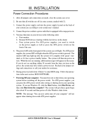
...running, additional messages will then run power-on the screen. The system will appear on tests. Follow the instructions in the next section, BIOS SOFTWARE. * Powering Off your computer: You must first exit or shut down to your computer" will light. III. INSTALLATION Power Connection ... power supplies, the system LED will give three quick beeps after about 30 seconds and then power off (in the following order: a. ASUS P2B-D/P2B-DS User's Manual 35 After all switches are made, close the system case cover. 2. The system will light when the ATX power switch is...
...running, additional messages will then run power-on the screen. The system will appear on tests. Follow the instructions in the next section, BIOS SOFTWARE. * Powering Off your computer: You must first exit or shut down to your computer" will light. III. INSTALLATION Power Connection ... power supplies, the system LED will give three quick beeps after about 30 seconds and then power off (in the following order: a. ASUS P2B-D/P2B-DS User's Manual 35 After all switches are made, close the system case cover. 2. The system will light when the ATX power switch is...
P2B-D User Manual
Page 36
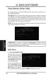
... bootup. Type a filename and the path, for example, A:\440BX-1 and then press . 36 ASUS P2B-D/P2B-DS User's Manual Main Menu 1. IV. NOTE: The following screen displays are provided as examples only and may not reflect the screen contents displayed on the motherboard. BIOS SOFTWARE Flash Memory Writer Utility This motherboard has an onboard SCSI...
... bootup. Type a filename and the path, for example, A:\440BX-1 and then press . 36 ASUS P2B-D/P2B-DS User's Manual Main Menu 1. IV. NOTE: The following screen displays are provided as examples only and may not reflect the screen contents displayed on the motherboard. BIOS SOFTWARE Flash Memory Writer Utility This motherboard has an onboard SCSI...

P2B-D User Manual
Page 37
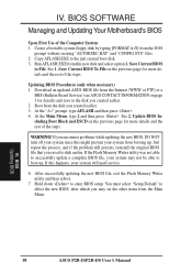
... Follow the onscreen instructions to start the update. The Update BIOS Including Boot Block and ESCD screen appears. Update BIOS Including Boot Block and ESCD This option updates the boot block, the baseboard BIOS, and the ACPI extended system configuration data (ESCD) parameter...new BIOS file. The utility starts to program the new BIOS information into the flash ROM. See the next page for example, A:\BX2I1002.AWD, and then press . When the programming is finished, Flashed Successfully will be displayed. IV. BIOS SOFTWARE 2. BIOS Flash Memory Writer ASUS P2B-D/P2B-DS User...
... Follow the onscreen instructions to start the update. The Update BIOS Including Boot Block and ESCD screen appears. Update BIOS Including Boot Block and ESCD This option updates the boot block, the baseboard BIOS, and the ACPI extended system configuration data (ESCD) parameter...new BIOS file. The utility starts to program the new BIOS information into the flash ROM. See the next page for example, A:\BX2I1002.AWD, and then press . When the programming is finished, Flashed Successfully will be displayed. IV. BIOS SOFTWARE 2. BIOS Flash Memory Writer ASUS P2B-D/P2B-DS User...
P2B-D User Manual
Page 38
... which you may not be able to the disk you saved to File. See 2. BIOS Updating BIOS 38 ASUS P2B-D/P2B-DS User's Manual Save Current BIOS To File on the previous page for more details and the rest of the Computer System 1. At the "A:\" prompt, type AFLASH and then press .... 4. At the Main Menu, type 2 and then press . Update BIOS Including Boot Block and ESCD on page 3 for details)...
... which you may not be able to the disk you saved to File. See 2. BIOS Updating BIOS 38 ASUS P2B-D/P2B-DS User's Manual Save Current BIOS To File on the previous page for more details and the rest of the Computer System 1. At the "A:\" prompt, type AFLASH and then press .... 4. At the Main Menu, type 2 and then press . Update BIOS Including Boot Block and ESCD on page 3 for details)...


