
P2B-D User Manual
Page 2
...Manual updates are trademarks of the product is defaced or missing. For previous or updated manuals, BIOS, drivers, or product release information, contact ASUS at http://www.asus.com.tw or through any means, except documentation kept by the third digit in the manual revision...' benefit, without the express written permission of the means indicated on the product itself. Product Name: ASUS P2B-D/P2B-DS Manual Revision: 1.06 E429 Release Date: July 1999 2 ASUS P2B-D/P2B-DS User's Manual Product warranty or service will not be reproduced, transmitted, transcribed, stored in a ...
...Manual updates are trademarks of the product is defaced or missing. For previous or updated manuals, BIOS, drivers, or product release information, contact ASUS at http://www.asus.com.tw or through any means, except documentation kept by the third digit in the manual revision...' benefit, without the express written permission of the means indicated on the product itself. Product Name: ASUS P2B-D/P2B-DS Manual Revision: 1.06 E429 Release Date: July 1999 2 ASUS P2B-D/P2B-DS User's Manual Product warranty or service will not be reproduced, transmitted, transcribed, stored in a ...

P2B-D User Manual
Page 4
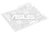
... Port 25 5. Motherboard Settings 12 Jumper Settings 13 2. System Memory (DIMM 17 DIMM Memory Installation Procedures 18 3. BIOS Setup 39 Load Defaults 40 Standard CMOS Setup 40 Details of Standard CMOS Setup 40 BIOS Features Setup 43 Details of BIOS Features Setup 43 4 ASUS P2B-D/P2B-DS User's Manual CONTENTS I. FEATURES 8 Features 8 The ASUS P2B-D/P2B-DS Motherboard 9 III.
... Port 25 5. Motherboard Settings 12 Jumper Settings 13 2. System Memory (DIMM 17 DIMM Memory Installation Procedures 18 3. BIOS Setup 39 Load Defaults 40 Standard CMOS Setup 40 Details of Standard CMOS Setup 40 BIOS Features Setup 43 Details of BIOS Features Setup 43 4 ASUS P2B-D/P2B-DS User's Manual CONTENTS I. FEATURES 8 Features 8 The ASUS P2B-D/P2B-DS Motherboard 9 III.
P2B-D User Manual
Page 5
...BIOS Defaults 54 Load Setup Defaults 54 Supervisor Password and User Password 55 IDE HDD Auto Detection 56 Save & Exit Setup 57 Exit Without Saving 57 V. ADAPTEC SCSI SELECT 65 Configuring the SCSI Adapter 65 VIII. ASUS LAN Card 75 ASUS PCI-L101 Fast Ethernet Card 75 Features 76 ASUS P2B-D/P2B...-DS User's Manual 5 SOFTWARE SETUP 58 ASUS Smart Motherboard Support CD 58 Installation Submenu 59 DOS Utility Submenu 60 ASUS Contact Information 61 VI. ADAPTEC ...
...BIOS Defaults 54 Load Setup Defaults 54 Supervisor Password and User Password 55 IDE HDD Auto Detection 56 Save & Exit Setup 57 Exit Without Saving 57 V. ADAPTEC SCSI SELECT 65 Configuring the SCSI Adapter 65 VIII. ASUS LAN Card 75 ASUS PCI-L101 Fast Ethernet Card 75 Features 76 ASUS P2B-D/P2B...-DS User's Manual 5 SOFTWARE SETUP 58 ASUS Smart Motherboard Support CD 58 Installation Submenu 59 DOS Utility Submenu 60 ASUS Contact Information 61 VI. ADAPTEC ...

P2B-D User Manual
Page 7
...for (1) 5.25" and (2) 3.5" floppy disk drives (1) Bag of spare jumpers (1) Support drivers and utilities (1) This Motherboard User's Manual (1) ASUS C-P2T PC100 Rev. 1.02 or later (1) Adaptec 7800 Family Manager Set User's Manual (optional) 68-pin Ultra2 SCSI cable with terminator (optional...optional) PS/2 Mouse, Infrared, USB1, and USB2 external connector module (optional) ASUS PCI-L101 Wake-On-LAN 10/100 Ethernet Card (optional) ASUS P2B-D/P2B-DS User's Manual 7 Desktop Management BIOS supported Desktop Management Interface VII. If you discover damaged or missing items, contact your...
...for (1) 5.25" and (2) 3.5" floppy disk drives (1) Bag of spare jumpers (1) Support drivers and utilities (1) This Motherboard User's Manual (1) ASUS C-P2T PC100 Rev. 1.02 or later (1) Adaptec 7800 Family Manager Set User's Manual (optional) 68-pin Ultra2 SCSI cable with terminator (optional...optional) PS/2 Mouse, Infrared, USB1, and USB2 external connector module (optional) ASUS PCI-L101 Wake-On-LAN 10/100 Ethernet Card (optional) ASUS P2B-D/P2B-DS User's Manual 7 Desktop Management BIOS supported Desktop Management Interface VII. If you discover damaged or missing items, contact your...

P2B-D User Manual
Page 8
...Expansion Slots: Provides four 32-bit PCI and two 16-bit ISA PCI slots. FEA TURES Specifications II. II. FEATURES Features The ASUS P2B-D/P2B-DS motherboards are necessary to communicate within a standard protocol creating a higher level of most devices for wireless connections. • Desktop ...Supports an optional infrared port module for Windows 98 compatibility, built-in hardware-based virus protection through BIOS, which is used to the memory and processor. 8 ASUS P2B-D/P2B-DS User's Manual These new SDRAMs are carefully designed for the demanding PC user who wants ...
...Expansion Slots: Provides four 32-bit PCI and two 16-bit ISA PCI slots. FEA TURES Specifications II. II. FEATURES Features The ASUS P2B-D/P2B-DS motherboards are necessary to communicate within a standard protocol creating a higher level of most devices for wireless connections. • Desktop ...Supports an optional infrared port module for Windows 98 compatibility, built-in hardware-based virus protection through BIOS, which is used to the memory and processor. 8 ASUS P2B-D/P2B-DS User's Manual These new SDRAMs are carefully designed for the demanding PC user who wants ...

P2B-D User Manual
Page 10
INSTALLATION ASUS P2B-D/P2B-DS Motherboard Layout PS/2 MOUSE (TOP PORT) KEYBOARD (BOTTOM) CPU_FAN USB USB 1(TOP PORT) USB 2 (BOTTOM) COM 1 COM 2 Slot1 for CPU 2 BUS FREQ Intel 440BX AGPset Multi-I/O Chip SB-LINK™ Connector Hardware Monitor RT2 2Mbit Flash EEPROM (Programmable BIOS) JP4 JP5... Connector ISA Slot 1 ISA Slot 2 NOTE: Grayed items are optional/reserved for CPU 1 III. III. CLRTC ASUS A97127F Chipset CHA_FAN JP18 CHASSIS EXTBATT IrDA 10 ASUS P2B-D/P2B-DS User's Manual INST ALLATION Motherboard Layout FS0 FS1 FS2 DIMM Socket 3 (64 bit, 168 pin module) DIMM...
INSTALLATION ASUS P2B-D/P2B-DS Motherboard Layout PS/2 MOUSE (TOP PORT) KEYBOARD (BOTTOM) CPU_FAN USB USB 1(TOP PORT) USB 2 (BOTTOM) COM 1 COM 2 Slot1 for CPU 2 BUS FREQ Intel 440BX AGPset Multi-I/O Chip SB-LINK™ Connector Hardware Monitor RT2 2Mbit Flash EEPROM (Programmable BIOS) JP4 JP5... Connector ISA Slot 1 ISA Slot 2 NOTE: Grayed items are optional/reserved for CPU 1 III. III. CLRTC ASUS A97127F Chipset CHA_FAN JP18 CHASSIS EXTBATT IrDA 10 ASUS P2B-D/P2B-DS User's Manual INST ALLATION Motherboard Layout FS0 FS1 FS2 DIMM Socket 3 (64 bit, 168 pin module) DIMM...

P2B-D User Manual
Page 12
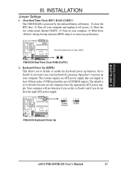
III. Setup the BIOS Software 1. Computer motherboards, baseboards and components, such as the power supply case. 3. If you do not have one, touch both of switches and/or jumpers. ... computer. 1. Motherboard Settings This section explains in detail how to touch the IC chips, leads or connectors, or other components. 4. INST ALLATION Motherboard Settings 12 ASUS P2B-D/P2B-DS User's Manual Install the Central Processing Unit (CPU) 4.
III. Setup the BIOS Software 1. Computer motherboards, baseboards and components, such as the power supply case. 3. If you do not have one, touch both of switches and/or jumpers. ... computer. 1. Motherboard Settings This section explains in detail how to touch the IC chips, leads or connectors, or other components. 4. INST ALLATION Motherboard Settings 12 ASUS P2B-D/P2B-DS User's Manual Install the Central Processing Unit (CPU) 4.
P2B-D User Manual
Page 13
... Short the two solder points labeled CLRTC, (3) Turn on the +5VSB lead and the new ACPI BIOS support. This feature requires an ATX power supply that can supply at least 300mA on your computer, (4) Hold ...down during bootup and enter BIOS setup to re-enter user preferences. 1 R 1 Short the solder points to disable or enable the ...have the right ATX power supply. 123 Disable (Default) 123 Enable 1 R 1 P2B-D/DS Keyboard Power Up ASUS P2B-D/P2B-DS User's Manual 13 III. INST ALLATION Motherboard Settings III.
... Short the two solder points labeled CLRTC, (3) Turn on the +5VSB lead and the new ACPI BIOS support. This feature requires an ATX power supply that can supply at least 300mA on your computer, (4) Hold ...down during bootup and enter BIOS setup to re-enter user preferences. 1 R 1 Short the solder points to disable or enable the ...have the right ATX power supply. 123 Disable (Default) 123 Enable 1 R 1 P2B-D/DS Keyboard Power Up ASUS P2B-D/P2B-DS User's Manual 13 III. INST ALLATION Motherboard Settings III.

P2B-D User Manual
Page 17
...) and make the proper settings through SDRAM Configuration under this User's Manual was written, 256MB DIMMs are only available as registered memory. BIOS SOFTWARE. Sockets are generally thinner with and without ECC. • SDRAM chips are available for 3.3Volt (power level) unbuffered Synchronous Dynamic... with higher pin density than EDO (Extended Data Output) chips. • BIOS shows SDRAM memory on the motherboard. Install memory in 32, 64, 128, 256MB. INST ALLATION System Memory III. ASUS P2B-D/P2B-DS User's Manual 17 One side (with memory chips) of the strict ...
...) and make the proper settings through SDRAM Configuration under this User's Manual was written, 256MB DIMMs are only available as registered memory. BIOS SOFTWARE. Sockets are generally thinner with and without ECC. • SDRAM chips are available for 3.3Volt (power level) unbuffered Synchronous Dynamic... with higher pin density than EDO (Extended Data Output) chips. • BIOS shows SDRAM memory on the motherboard. Install memory in 32, 64, 128, 256MB. INST ALLATION System Memory III. ASUS P2B-D/P2B-DS User's Manual 17 One side (with memory chips) of the strict ...
P2B-D User Manual
Page 24
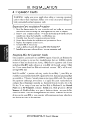
.... Set up the BIOS if necessary (such as jumpers. 2. If your computer will experience problems when those two devices are two types of ISA cards. Make sure that you a Device Manager tab. Failure to as legacy ISA cards, requires that no two devices use at the same time. 24 ASUS P2B-D/P2B-DS User...
.... Set up the BIOS if necessary (such as jumpers. 2. If your computer will experience problems when those two devices are two types of ISA cards. Make sure that you a Device Manager tab. Failure to as legacy ISA cards, requires that no two devices use at the same time. 24 ASUS P2B-D/P2B-DS User...

P2B-D User Manual
Page 25
... automatically assigned to support a new generation of the BIOS setup utility can contact your PCI cards are being used by Legacy cards. For PnP cards, IRQs are handled the same way as the ASUS AGP-V2740 3D Multimedia Accelerator. 1 R 1 P2B-D/DS Accelerated Graphics Port (AGP) ASUS P2B-D/P2B-DS User's Manual 25 Since all the PCI...
... automatically assigned to support a new generation of the BIOS setup utility can contact your PCI cards are being used by Legacy cards. For PnP cards, IRQs are handled the same way as the ASUS AGP-V2740 3D Multimedia Accelerator. 1 R 1 P2B-D/DS Accelerated Graphics Port (AGP) ASUS P2B-D/P2B-DS User's Manual 25 Since all the PCI...

P2B-D User Manual
Page 26
... the connectors before installation because there may be on the opposite side on the connectors. You may be exceptions. PS/2 Mouse (6-pin Female) 26 ASUS P2B-D/P2B-DS User's Manual III. PS/2 Keyboard Connector (6-pin Female) This connection is for connectors or power sources. PS/2 Keyboard (6-pin Female) 2. ...on standard AT keyboards. IDE ribbon cables must be connected with the second drive connector no more than 15 cm (6 in BIOS Features Setup of the BIOS SOFTWARE. PS/2 Mouse Connector (6-pin Female) The system will direct IRQ12 to the PS/2 mouse if one is usually on...
... the connectors before installation because there may be on the opposite side on the connectors. You may be exceptions. PS/2 Mouse (6-pin Female) 26 ASUS P2B-D/P2B-DS User's Manual III. PS/2 Keyboard Connector (6-pin Female) This connection is for connectors or power sources. PS/2 Keyboard (6-pin Female) 2. ...on standard AT keyboards. IDE ribbon cables must be connected with the second drive connector no more than 15 cm (6 in BIOS Features Setup of the BIOS SOFTWARE. PS/2 Mouse Connector (6-pin Female) The system will direct IRQ12 to the PS/2 mouse if one is usually on...

P2B-D User Manual
Page 27
...enable the parallel port and choose the IRQ through "Onboard Parallel Port" in Chipset Features Setup of the BIOS SOFTWARE. in Chipset Features Setup of the BIOS SOFTWARE. Parallel Printer Connector (25-pin Female) You can be connected to the serial port. NOTE: ...Serial printers must be used for pointing devices or other end to the floppy drives. (Pin 5 is removed to Pin 1 Pin 1 Floppy Drive Connector P2B-D/DS Floppy Disk Drive Connector ASUS P2B-D/P2B...
...enable the parallel port and choose the IRQ through "Onboard Parallel Port" in Chipset Features Setup of the BIOS SOFTWARE. in Chipset Features Setup of the BIOS SOFTWARE. Parallel Printer Connector (25-pin Female) You can be connected to the serial port. NOTE: ...Serial printers must be used for pointing devices or other end to the floppy drives. (Pin 5 is removed to Pin 1 Pin 1 Floppy Drive Connector P2B-D/DS Floppy Disk Drive Connector ASUS P2B-D/P2B...
P2B-D User Manual
Page 28
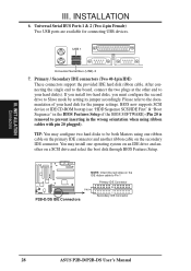
... hard disk for connecting USB devices. You may configure two hard disks to Pin 1 Primary IDE Connector PIN 1 P2B-D/DS IDE Connectors Secondary IDE Connector 28 ASUS P2B-D/P2B-DS User's Manual BIOS now supports SCSI device or IDE CD-ROM bootup (see "HDD Sequence SCSI/IDE First" & "Boot Sequence"... in the BIOS Features Setup of your hard disk(s). After connecting the single end to the board, connect the ...
... hard disk for connecting USB devices. You may configure two hard disks to Pin 1 Primary IDE Connector PIN 1 P2B-D/DS IDE Connectors Secondary IDE Connector 28 ASUS P2B-D/P2B-DS User's Manual BIOS now supports SCSI device or IDE CD-ROM bootup (see "HDD Sequence SCSI/IDE First" & "Boot Sequence"... in the BIOS Features Setup of your hard disk(s). After connecting the single end to the board, connect the ...

P2B-D User Manual
Page 31
... WOLCON) This connector connects to LAN cards with the optional hardware monitor installed. 1 R 1 1 R 1 P2B-D/DS Chassis Open Alarm Lead +5VSB Chassis Signal (High Active) Ground ASUS P2B-D/P2B-DS User's Manual 31 INST ALLATION Connectors III. Chassis Intrusion Sensor Lead (CHASSIS) This lead is received through ...the LAN card. This occurs when the side panel is set to the CHASSIS lead. III. BIOS SOFTWARE) and that the ...
... WOLCON) This connector connects to LAN cards with the optional hardware monitor installed. 1 R 1 1 R 1 P2B-D/DS Chassis Open Alarm Lead +5VSB Chassis Signal (High Active) Ground ASUS P2B-D/P2B-DS User's Manual 31 INST ALLATION Connectors III. Chassis Intrusion Sensor Lead (CHASSIS) This lead is received through ...the LAN card. This occurs when the side panel is set to the CHASSIS lead. III. BIOS SOFTWARE) and that the ...

P2B-D User Manual
Page 32
...This may use the "Turbo Switch". This 2-pin connector connects to the case-mounted speaker. The system power LED shows the status of the BIOS SOFTWARE section to save electricity and expand the life of the system's power supply. 18. Keyboard Lock Power LED Speaker Connector +5 V PLED ...MSG LED Reset SW SMI Lead ATX Power Switch* P2B-D/DS System Panel Connections * Requires an ATX power supply. 32 ASUS P2B-D/P2B-DS User's Manual ATX Power Switch / Soft Power Switch (PWR.SW) The system power is in the BIOS but the keyboard will switch the system between ON and...
...This may use the "Turbo Switch". This 2-pin connector connects to the case-mounted speaker. The system power LED shows the status of the BIOS SOFTWARE section to save electricity and expand the life of the system's power supply. 18. Keyboard Lock Power LED Speaker Connector +5 V PLED ...MSG LED Reset SW SMI Lead ATX Power Switch* P2B-D/DS System Panel Connections * Requires an ATX power supply. 32 ASUS P2B-D/P2B-DS User's Manual ATX Power Switch / Soft Power Switch (PWR.SW) The system power is in the BIOS but the keyboard will switch the system between ON and...
P2B-D User Manual
Page 35
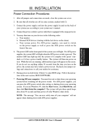
...will light. Your system power. While the tests are off your devices in the following order: a. If you turn on the chain) c. ASUS P2B-D/P2B-DS User's Manual 35 Be sure that is pressed. The system will appear on the front panel of the case. 6. NOTE: The ... with a surge protector. 5. INSTALLATION Power Connection Procedures 1. For ATX power supplies, you can now safely turn off (in the next section, BIOS SOFTWARE. * Powering Off your operating system. For ATX power supplies, you need to your retailer for assistance. 7. After all switches are running,...
...will light. Your system power. While the tests are off your devices in the following order: a. If you turn on the chain) c. ASUS P2B-D/P2B-DS User's Manual 35 Be sure that is pressed. The system will appear on the front panel of the case. 6. NOTE: The ... with a surge protector. 5. INSTALLATION Power Connection Procedures 1. For ATX power supplies, you can now safely turn off (in the next section, BIOS SOFTWARE. * Powering Off your operating system. For ATX power supplies, you need to your retailer for assistance. 7. After all switches are running,...
P2B-D User Manual
Page 36
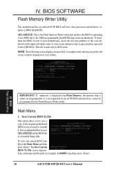
... copy of your system. To save AFLASH.EXE and the BIOS file to the 2Mbit programmable flash ROM chip on your screen during bootup. Type a filename and the path, for example, A:\440BX-1 and then press . 36 ASUS P2B-D/P2B-DS User's Manual IV. It is not supported by the... ACPI BIOS and therefore, cannot be programmed by uploading a new BIOS file to a bootable floppy disk. To determine the BIOS version of your current BIOS, type [1] at the Main Menu and then press...
... copy of your system. To save AFLASH.EXE and the BIOS file to the 2Mbit programmable flash ROM chip on your screen during bootup. Type a filename and the path, for example, A:\440BX-1 and then press . 36 ASUS P2B-D/P2B-DS User's Manual IV. It is not supported by the... ACPI BIOS and therefore, cannot be programmed by uploading a new BIOS file to a bootable floppy disk. To determine the BIOS version of your current BIOS, type [1] at the Main Menu and then press...

P2B-D User Manual
Page 37
... the ACPI extended system configuration data (ESCD) parameter block from a new BIOS file. The utility starts to start the update. Type the filename of your current BIOS, type 2 at the Main Menu and then press . BIOS Flash Memory Writer ASUS P2B-D/P2B-DS User's Manual 37 When the programming is finished, Flashed Successfully will be displayed...
... the ACPI extended system configuration data (ESCD) parameter block from a new BIOS file. The utility starts to start the update. Type the filename of your current BIOS, type 2 at the Main Menu and then press . BIOS Flash Memory Writer ASUS P2B-D/P2B-DS User's Manual 37 When the programming is finished, Flashed Successfully will be displayed...
P2B-D User Manual
Page 38
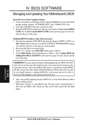
... the Main Menu, type 2 and then press . If this happens, your system from the DOS prompt without creating "AUTOEXEC.BAT" and "CONFIG.SYS" files. 2. BIOS Updating BIOS 38 ASUS P2B-D/P2B-DS User's Manual Create a bootable system floppy disk by typing [FORMAT A:/S] from booting up . If you created earlier. 2. Copy AFLASH.EXE to File. Update...
... the Main Menu, type 2 and then press . If this happens, your system from the DOS prompt without creating "AUTOEXEC.BAT" and "CONFIG.SYS" files. 2. BIOS Updating BIOS 38 ASUS P2B-D/P2B-DS User's Manual Create a bootable system floppy disk by typing [FORMAT A:/S] from booting up . If you created earlier. 2. Copy AFLASH.EXE to File. Update...


