TravelMate 4730/4730G Service Guide
Page 7
...Keys and embedded numeric keypad 12 Windows Keys 13 Hot Keys 14 Special Key 15 Using the System Utilities 16 Acer GridVista (dual-display compatible 16 Hardware Specifications and Configurations 18 System Utilities 25 BIOS Setup Utility 25 Navigating the ... BIOS Flash Utility 37 Remove HDD/BIOS Utility 39 Machine Disassembly and Replacement 43 Disassembly Requirements 43 General Information 44 Pre-disassembly Instructions 44 Disassembly Process 44 External Module Disassembly Process 45 External Modules Disassembly Flowchart 45 Removing the Battery Pack 46 Removing the SD ...
...Keys and embedded numeric keypad 12 Windows Keys 13 Hot Keys 14 Special Key 15 Using the System Utilities 16 Acer GridVista (dual-display compatible 16 Hardware Specifications and Configurations 18 System Utilities 25 BIOS Setup Utility 25 Navigating the ... BIOS Flash Utility 37 Remove HDD/BIOS Utility 39 Machine Disassembly and Replacement 43 Disassembly Requirements 43 General Information 44 Pre-disassembly Instructions 44 Disassembly Process 44 External Module Disassembly Process 45 External Modules Disassembly Flowchart 45 Removing the Battery Pack 46 Removing the SD ...
TravelMate 4730/4730G Service Guide
Page 8
... 82 Removing the RJ-11 Port 83 Removing the Thermal Module 84 Removing the CPU 86 Removing the VGA Module 87 LCD Module Disassembly Process 88 LCD Module Disassembly Flowchart 88 Removing the LCD Bezel 89 Removing the Inverter Board 90 Removing the Camera Module 91 Removing the LCD Panel 93 Removing...
... 82 Removing the RJ-11 Port 83 Removing the Thermal Module 84 Removing the CPU 86 Removing the VGA Module 87 LCD Module Disassembly Process 88 LCD Module Disassembly Flowchart 88 Removing the LCD Bezel 89 Removing the Inverter Board 90 Removing the Camera Module 91 Removing the LCD Panel 93 Removing...
TravelMate 4730/4730G Service Guide
Page 53
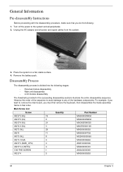
... flat screwdriver • Plastic tweezers NOTE: The screws for maintenance and troubleshooting. During the disassembly process, group the screws with the corresponding components to disassemble the notebook computer for the different components vary in size. Chapter 3 43 Machine Disassembly and Replacement Chapter 3 This chapter contains step-by-step procedures on how to avoid...
... flat screwdriver • Plastic tweezers NOTE: The screws for maintenance and troubleshooting. During the disassembly process, group the screws with the corresponding components to disassemble the notebook computer for the different components vary in size. Chapter 3 43 Machine Disassembly and Replacement Chapter 3 This chapter contains step-by-step procedures on how to avoid...
TravelMate 4730/4730G Service Guide
Page 54
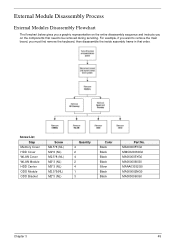
... inside assembly frame in that you do the following stages: • External module disassembly • Main unit disassembly • LCD module disassembly The flowcharts provided in the succeeding disassembly sections illustrate the entire disassembly sequence. Main Screw List Screw Quantity Part Number M2.5*3 (NL) 19 MA000005WG0 M2.5*5 (NL) 9 ...the battery pack. Unplug the AC adapter and all peripherals. 2. Place the system on a flat, stable surface. 4. Disassembly Process The disassembly process is divided into the following : 1. General Information Pre...
... inside assembly frame in that you do the following stages: • External module disassembly • Main unit disassembly • LCD module disassembly The flowcharts provided in the succeeding disassembly sections illustrate the entire disassembly sequence. Main Screw List Screw Quantity Part Number M2.5*3 (NL) 19 MA000005WG0 M2.5*5 (NL) 9 ...the battery pack. Unplug the AC adapter and all peripherals. 2. Place the system on a flat, stable surface. 4. Disassembly Process The disassembly process is divided into the following : 1. General Information Pre...
TravelMate 4730/4730G Service Guide
Page 55
...*3 (NL) Quantity 4 2 4 2 4 1 3 Color Black Black Black Black Silver Black Black Part No. MA000005YG0 MMCK20060G0 MA000005YG0 MA0000060G0 MAAA03032G0 MA000002NG0 MA0000060G0 Chapter 3 45 External Module Disassembly Process External Modules Disassembly Flowchart The flowchart below gives you a graphic representation on the components that order. For example, if you want to remove the main board, you...
...*3 (NL) Quantity 4 2 4 2 4 1 3 Color Black Black Black Black Silver Black Black Part No. MA000005YG0 MMCK20060G0 MA000005YG0 MA0000060G0 MAAA03032G0 MA000002NG0 MA0000060G0 Chapter 3 45 External Module Disassembly Process External Modules Disassembly Flowchart The flowchart below gives you a graphic representation on the components that order. For example, if you want to remove the main board, you...

TravelMate 4730/4730G Service Guide
Page 68
MA0000060G0 MA000005YG0 MA000007YG0 MA000005YG0 MA000007YG0 MA0000060G0 MA0000060G0 MA0000060G0 MA000007YG0 MA0000060G0 MA0000060G0 MA000007YG0 MA0000096G0 58 Chapter 3 Main Unit Disassembly Process Main Unit Disassembly Flowchart Screw List Step Switch Cover LCD Module LCD Module Upper Cover Upper Cover Touch Pad Bracket Launch Board Speaker I/O Board Bluetooth Board Modem Module ...
MA0000060G0 MA000005YG0 MA000007YG0 MA000005YG0 MA000007YG0 MA0000060G0 MA0000060G0 MA0000060G0 MA000007YG0 MA0000060G0 MA0000060G0 MA000007YG0 MA0000096G0 58 Chapter 3 Main Unit Disassembly Process Main Unit Disassembly Flowchart Screw List Step Switch Cover LCD Module LCD Module Upper Cover Upper Cover Touch Pad Bracket Launch Board Speaker I/O Board Bluetooth Board Modem Module ...
TravelMate 4730/4730G Service Guide
Page 89
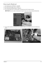
Turn the lower base over on page 67. 3. Chapter 3 79 Removing the Mainboard 1. See "Removing the Upper Cover" on a clean surface, and disconnect the DC-IN cable as shown. See "Removing the LCD Module" on page 78. 4. See "Removing the Modem Module" on page 65. 2. Turn the base rightside up, and disconnect the bluetooth cable from the bottom right of the mainboard as shown. IMPORTANT:Ensure the cable can easily pass through the lower cover during mainboard disassembly. 5.
Turn the lower base over on page 67. 3. Chapter 3 79 Removing the Mainboard 1. See "Removing the Upper Cover" on a clean surface, and disconnect the DC-IN cable as shown. See "Removing the LCD Module" on page 78. 4. See "Removing the Modem Module" on page 65. 2. Turn the base rightside up, and disconnect the bluetooth cable from the bottom right of the mainboard as shown. IMPORTANT:Ensure the cable can easily pass through the lower cover during mainboard disassembly. 5.
TravelMate 4730/4730G Service Guide
Page 135
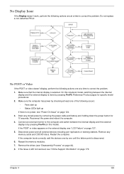
.... 3. Reseat the memory modules. 7. Chapter 4 125 Connect an external monitor to correct the problem. Make sure that the internal display is still not resolved, see "Disassembly Process" on page 127. 5.
.... 3. Reseat the memory modules. 7. Chapter 4 125 Connect an external monitor to correct the problem. Make sure that the internal display is still not resolved, see "Disassembly Process" on page 127. 5.
TravelMate 4730/4730G Service Guide
Page 136
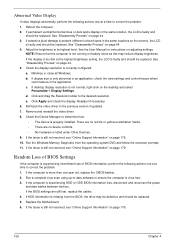
...setting, the LCD is experiencing intermittent loss of BIOS information, perform the following actions one at a time to correct the problem. 1. See "Disassembly Process" on page 44. 3. d. e. There are no red Xs or yellow exclamation marks. • There are still lost, replace the cables. 4. ...See "Disassembly Process" on page 44. 5. Check the display resolution is more than one year old, replace the CMOS battery. 2. Readjust if necessary. 6. Random ...
...setting, the LCD is experiencing intermittent loss of BIOS information, perform the following actions one at a time to correct the problem. 1. See "Disassembly Process" on page 44. 3. d. e. There are no red Xs or yellow exclamation marks. • There are still lost, replace the cables. 4. ...See "Disassembly Process" on page 44. 5. Check the display resolution is more than one year old, replace the CMOS battery. 2. Readjust if necessary. 6. Random ...
TravelMate 4730/4730G Service Guide
Page 141
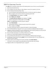
... locate and resolve issues with the computer. Remove any key to start to resolve the problem. 4. For more information see Windows Help and Support. 9. See "Disassembly Process" on the Boot menu. 6. Chapter 4 131 Select Repair your computer. f. Startup Repair attempts to enter the BIOS Utility. Check the BIOS settings are required...
... locate and resolve issues with the computer. Remove any key to start to resolve the problem. 4. For more information see Windows Help and Support. 9. See "Disassembly Process" on the Boot menu. 6. Chapter 4 131 Select Repair your computer. f. Startup Repair attempts to enter the BIOS Utility. Check the BIOS settings are required...
TravelMate 4730/4730G Service Guide
Page 144
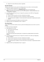
..."Hardware Specifications and Configurations" on page 44. Restart the computer and press F2 to the ODD. Check for the other discs. b. See "Disassembly Process" on the drive, motherboard, and cables. Drive Read Failure If discs cannot be replaced. 4. Test the drive using other ATA Devices ...Repeat for broken connectors on page 44. Turn off the power and remove the cover to inspect the connections to correct the problem. 1. See "Disassembly Process" on page 18. 3. NOTE: Check that the drive is probably defective and should be replaced. 3. Turn off the power and remove...
..."Hardware Specifications and Configurations" on page 44. Restart the computer and press F2 to the ODD. Check for the other discs. b. See "Disassembly Process" on the drive, motherboard, and cables. Drive Read Failure If discs cannot be replaced. 4. Test the drive using other ATA Devices ...Repeat for broken connectors on page 44. Turn off the power and remove the cover to inspect the connections to correct the problem. 1. See "Disassembly Process" on page 18. 3. NOTE: Check that the drive is probably defective and should be replaced. 3. Turn off the power and remove...
TravelMate 4730/4730G Service Guide
Page 192
LCD Bezel 89 LCD Brackets 94 LCD Failure 127 LCD Module Disassembly Flowchart 88 LCD Panel 93 lower cover 49 M Main Unit Disassembly Flowchart 58 Mainboard 79 media access on indicator 10 MediaTouch Button Failure 138 Memory Check 124 Model Definition 166 Modem Failure 135 Modem Module 78 N ...
LCD Bezel 89 LCD Brackets 94 LCD Failure 127 LCD Module Disassembly Flowchart 88 LCD Panel 93 lower cover 49 M Main Unit Disassembly Flowchart 58 Mainboard 79 media access on indicator 10 MediaTouch Button Failure 138 Memory Check 124 Model Definition 166 Modem Failure 135 Modem Module 78 N ...


