TravelMate 4730/4730G Service Guide
Page 7
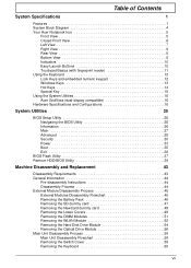
...Basics (with fingerprint reader 11 Using the Keyboard 12 Lock Keys and embedded numeric keypad 12 Windows Keys 13 Hot Keys 14 Special Key 15 Using the System Utilities 16 Acer GridVista (dual-display compatible 16 Hardware Specifications...Removing the SD dummy card 47 Removing the NewCard dummy card 48 Removing the Lower Covers 49 Removing the DIMM Modules 51 Removing the WLAN Module 52 Removing the Hard Disk Drive Module 54 Removing the Optical Drive Module 56 Main Unit Disassembly Process 58 Main Unit Disassembly Flowchart 58 Removing the Switch Cover 59 Removing the Keyboard...
...Basics (with fingerprint reader 11 Using the Keyboard 12 Lock Keys and embedded numeric keypad 12 Windows Keys 13 Hot Keys 14 Special Key 15 Using the System Utilities 16 Acer GridVista (dual-display compatible 16 Hardware Specifications...Removing the SD dummy card 47 Removing the NewCard dummy card 48 Removing the Lower Covers 49 Removing the DIMM Modules 51 Removing the WLAN Module 52 Removing the Hard Disk Drive Module 54 Removing the Optical Drive Module 56 Main Unit Disassembly Process 58 Main Unit Disassembly Flowchart 58 Removing the Switch Cover 59 Removing the Keyboard...
TravelMate 4730/4730G Service Guide
Page 8
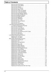
...Removing the Power Board 61 Removing the Launch Board 62 Removing the Antenna 63 Removing the LCD Module 65 Removing the Upper Cover 67 Removing the Finger Print Reader 71 Removing the Touch Pad Bracket 73 Removing the Left Speaker Module 74 Removing the Right Speaker Module 76 Removing the Bluetooth Module 77 Removing the Modem Module 78 Removing the Mainboard 79 Removing... the Upper Cover 111 Replacing the LCD Module 113 Replacing the Antenna Cables 115 Replacing the Keyboard 117 Replacing the Switch Cover 117 Replacing the WLAN Module 119 Replacing the Hard Disk Drive ...
...Removing the Power Board 61 Removing the Launch Board 62 Removing the Antenna 63 Removing the LCD Module 65 Removing the Upper Cover 67 Removing the Finger Print Reader 71 Removing the Touch Pad Bracket 73 Removing the Left Speaker Module 74 Removing the Right Speaker Module 76 Removing the Bluetooth Module 77 Removing the Modem Module 78 Removing the Mainboard 79 Removing... the Upper Cover 111 Replacing the LCD Module 113 Replacing the Antenna Cables 115 Replacing the Keyboard 117 Replacing the Switch Cover 117 Replacing the WLAN Module 119 Replacing the Hard Disk Drive ...
TravelMate 4730/4730G Service Guide
Page 54
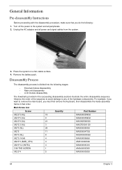
...power to the system and all power and signal cables from the system. 3. Place the system on a flat, stable surface. 4. Remove the battery pack. For example, if you want to any of the hardware components. Main Screw List Screw Quantity Part Number M2.5*3 (... Information Pre-disassembly Instructions Before proceeding with the disassembly procedure, make sure that order. Observe the order of the sequence to avoid damage to remove the main board, you do the following stages: • External module disassembly • Main unit disassembly • LCD module disassembly The ...
...power to the system and all power and signal cables from the system. 3. Place the system on a flat, stable surface. 4. Remove the battery pack. For example, if you want to any of the hardware components. Main Screw List Screw Quantity Part Number M2.5*3 (... Information Pre-disassembly Instructions Before proceeding with the disassembly procedure, make sure that order. Observe the order of the sequence to avoid damage to remove the main board, you do the following stages: • External module disassembly • Main unit disassembly • LCD module disassembly The ...
TravelMate 4730/4730G Service Guide
Page 55
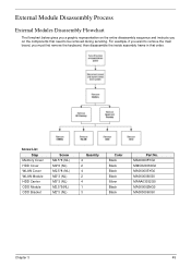
... The flowchart below gives you a graphic representation on the entire disassembly sequence and instructs you must first remove the keyboard, then disassemble the inside assembly frame in that need to remove the main board, you on the components that order. For example, if you want to be... removed during servicing. Screw List Step Memory Cover HDD Cover WLAN Cover WLAN Module HDD Carrier ODD Module ODD Bracket Screw ...
... The flowchart below gives you a graphic representation on the entire disassembly sequence and instructs you must first remove the keyboard, then disassemble the inside assembly frame in that need to remove the main board, you on the components that order. For example, if you want to be... removed during servicing. Screw List Step Memory Cover HDD Cover WLAN Cover WLAN Module HDD Carrier ODD Module ODD Bracket Screw ...
TravelMate 4730/4730G Service Guide
Page 70
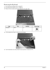
See "Removing the Switch Cover" on page 46. 2. Screw Type 5. Removing the Keyboard 1. Turn the keyboard over and pull back the securing latch to remove from the chassis. See "Removing the Battery Pack" on page 59. 3. Step Keyboard Size M2*3 Quantity 2 4. Lift the keyboard as shown to release the FFC. 60 Chapter 3 Remove the two screws securing the keyboard to the upper case.
See "Removing the Switch Cover" on page 46. 2. Screw Type 5. Removing the Keyboard 1. Turn the keyboard over and pull back the securing latch to remove from the chassis. See "Removing the Battery Pack" on page 59. 3. Step Keyboard Size M2*3 Quantity 2 4. Lift the keyboard as shown to release the FFC. 60 Chapter 3 Remove the two screws securing the keyboard to the upper case.
TravelMate 4730/4730G Service Guide
Page 71
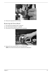
See "Removing the Keyboard" on page 46. 2. Remove the keyboard from the mainboard. 4. 6. NOTE: The left hand securing screw is shared by the eKey Board. Chapter 3 61 Removing the Power Board 1. Disconnect the Power Board cable from the chassis. Remove the two securing screws from the Power Board. See "Removing the Battery Pack" on page 60. 3.
See "Removing the Keyboard" on page 46. 2. Remove the keyboard from the mainboard. 4. 6. NOTE: The left hand securing screw is shared by the eKey Board. Chapter 3 61 Removing the Power Board 1. Disconnect the Power Board cable from the chassis. Remove the two securing screws from the Power Board. See "Removing the Battery Pack" on page 60. 3.
TravelMate 4730/4730G Service Guide
Page 72
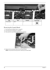
Screw Type 4. See "Removing the Keyboard" on page 46. 2. NOTE: The right hand securing screw is shared by the Power Board. 62 Chapter 3 Disconnect the Launch Board cable from the Launch Board. Remove the two securing screws from the mainboard. Step Power Board Size M2*3 Quantity 2 Removing the Launch Board 1. See "Removing the Battery Pack" on page 60. 3.
Screw Type 4. See "Removing the Keyboard" on page 46. 2. NOTE: The right hand securing screw is shared by the Power Board. 62 Chapter 3 Disconnect the Launch Board cable from the Launch Board. Remove the two securing screws from the mainboard. Step Power Board Size M2*3 Quantity 2 Removing the Launch Board 1. See "Removing the Battery Pack" on page 60. 3.


