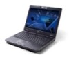
Acer TravelMate 4730 Battery
View Results Below
Free Acer TravelMate 4730 manuals!
Problems with Acer TravelMate 4730?
Ask a Question
Free Acer TravelMate 4730 manuals!
Problems with Acer TravelMate 4730?
Ask a Question
Related Manual Pages
Similar Questions


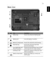
Bios Battery
I tried hard to find the bios battery of my acer travelmate 4330 laptop bt I cant find it can u plz ...
I tried hard to find the bios battery of my acer travelmate 4330 laptop bt I cant find it can u plz ...
(Posted by zainzoni14 12 years ago)

Battery Doesn't Charge
What software in my computer allows my battery to charge? This is because I have been unable to char...
What software in my computer allows my battery to charge? This is because I have been unable to char...
(Posted by gaiusnti 12 years ago)