TravelMate 3200 Service Guide
Page 7
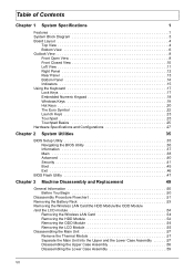
...Utility 36 Information 37 Main 38 Advanced 40 Security 41 Boot 45 Exit 46 BIOS Flash Utility 47 Chapter 3 Machine Disassembly and Replacement 49 General Information 50 Before You Begin 50 Disassembly Procedure Flowchart 51 Removing the Battery Pack 53 Removing the Wireless LAN Card/the HDD Module/the ODD Module /and... LCD module 54 Removing the Wireless LAN Card 54 Removing the HDD Module 54 Removing the ODD Module 54 Removing the LCD Module 55 Disassembling the Main Unit 57 Remove the Thermal Module 57 Separate the Main Unit Into the Upper and the Lower Case Assembly 57...
...Utility 36 Information 37 Main 38 Advanced 40 Security 41 Boot 45 Exit 46 BIOS Flash Utility 47 Chapter 3 Machine Disassembly and Replacement 49 General Information 50 Before You Begin 50 Disassembly Procedure Flowchart 51 Removing the Battery Pack 53 Removing the Wireless LAN Card/the HDD Module/the ODD Module /and... LCD module 54 Removing the Wireless LAN Card 54 Removing the HDD Module 54 Removing the ODD Module 54 Removing the LCD Module 55 Disassembling the Main Unit 57 Remove the Thermal Module 57 Separate the Main Unit Into the Upper and the Lower Case Assembly 57...
TravelMate 3200 Service Guide
Page 8
Table of Contents Disassembling the LCD Module 61 Disassembling the External Modules 63 Disassembling the HDD Module 63 Disassembling the Optical Drive Module 63 Chapter 4 Troubleshooting 65 System Check Procedures 66 External Diskette Drive Check 66 External CD-ROM ... 83 Bottom View 85 Chapter 6 FRU (Field Replaceable Unit) List 87 Exploded Diagram 88 Appendix A Model Definition and Configuration 96 TravelMate 3200 Series 96 Appendix B Test Compatible Components 97 Microsoft® Windows® XP Pro Environment Test 98 Appendix C Online Support Information 101 VIII
Table of Contents Disassembling the LCD Module 61 Disassembling the External Modules 63 Disassembling the HDD Module 63 Disassembling the Optical Drive Module 63 Chapter 4 Troubleshooting 65 System Check Procedures 66 External Diskette Drive Check 66 External CD-ROM ... 83 Bottom View 85 Chapter 6 FRU (Field Replaceable Unit) List 87 Exploded Diagram 88 Appendix A Model Definition and Configuration 96 TravelMate 3200 Series 96 Appendix B Test Compatible Components 97 Microsoft® Windows® XP Pro Environment Test 98 Appendix C Online Support Information 101 VIII
TravelMate 3200 Service Guide
Page 57
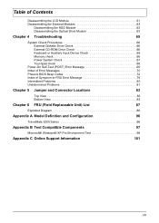
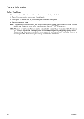
..., group the screws with the corresponding components to disassemble the notebook computer for the different components vary in size. When you need the following tools: T Wrist grounding strap and conductive mat for preventing ...electrostatic discharge T Small Philips screw driver T Philips screwdriver T Plastic flat head screw driver T Tweezers NOTE: The screws for maintenance and troubleshooting. Chapter 3 Machine Disassembly and Replacement This chapter contains step-by-step procedures on how to avoid mismatch when putting back the components. Chapter 3 49 To...
..., group the screws with the corresponding components to disassemble the notebook computer for the different components vary in size. When you need the following tools: T Wrist grounding strap and conductive mat for preventing ...electrostatic discharge T Small Philips screw driver T Philips screwdriver T Plastic flat head screw driver T Tweezers NOTE: The screws for maintenance and troubleshooting. Chapter 3 Machine Disassembly and Replacement This chapter contains step-by-step procedures on how to avoid mismatch when putting back the components. Chapter 3 49 To...
TravelMate 3200 Service Guide
Page 58
... signal cables from the system. 3. NOTE: TravelMate 3200 series product uses mylar or tape to fasten the FFC/FPC/connectors/cable, you disconnect different FFC/FPC/connectors. NOTE: There are several types of screws together during service disassembling. If you do the following: 1. General... Information Before You Begin Before proceeding with the disassembly procedure, make sure that you fasten the screw to the wrong location, the screw...
... signal cables from the system. 3. NOTE: TravelMate 3200 series product uses mylar or tape to fasten the FFC/FPC/connectors/cable, you disconnect different FFC/FPC/connectors. NOTE: There are several types of screws together during service disassembling. If you do the following: 1. General... Information Before You Begin Before proceeding with the disassembly procedure, make sure that you fasten the screw to the wrong location, the screw...
TravelMate 3200 Service Guide
Page 59
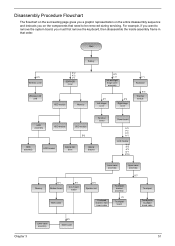
... The flowchart on the succeeding page gives you a graphic representation on the entire disassembly sequence and instructs you must first remove the keyboard, then disassemble the inside assembly frame in 1 card reader MDC cable Lower case assembly Upper case assembly E*4 Speaker set Touchpad board to main board cable Touchpad bracket ...
... The flowchart on the succeeding page gives you a graphic representation on the entire disassembly sequence and instructs you must first remove the keyboard, then disassemble the inside assembly frame in 1 card reader MDC cable Lower case assembly Upper case assembly E*4 Speaker set Touchpad board to main board cable Touchpad bracket ...
TravelMate 3200 Service Guide
Page 65
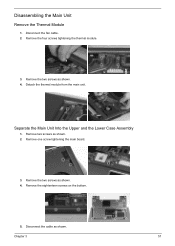
Remove one screw tightening the main board. 3. Remove the eightenteen screws on the bottom. 5. Disconnect the fan cable. 2. Remove the two screws as shown. Disconnect the cable as shown. 4. Detach the thermal module from the main unit. Separate the Main Unit Into the Upper and the Lower Case Assembly 1. Disassembling the Main Unit Remove the Thermal Module 1. Remove the two screws as shown. 2. Remove two screws as shown. 4. Chapter 3 57 Remove the four screws tightening the thermal module. 3.
Remove one screw tightening the main board. 3. Remove the eightenteen screws on the bottom. 5. Disconnect the fan cable. 2. Remove the two screws as shown. Disconnect the cable as shown. 4. Detach the thermal module from the main unit. Separate the Main Unit Into the Upper and the Lower Case Assembly 1. Disassembling the Main Unit Remove the Thermal Module 1. Remove the two screws as shown. 2. Remove two screws as shown. 4. Chapter 3 57 Remove the four screws tightening the thermal module. 3.
TravelMate 3200 Service Guide
Page 66
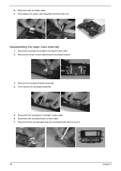
Disassembling the Upper Case Assembly 1. Then remove the touchpad assembly. 5. Disconnect touchpad touchpad to main cable. 7. Disconnect the touchpad board to touchpad board cable. 2. 6. Then detach the upper case assembly from the main unit. Remove the seven screws tightening the touchpad bracket. 3. Disconnect the touchpad cable. 7. Disconnect the touchpad to touchpad board cable. 6. Remove the touchpad bracket assembly. 4. Remove the two screws tightening the touchpad board then remove it. 58 Chapter 3
Disassembling the Upper Case Assembly 1. Then remove the touchpad assembly. 5. Disconnect touchpad touchpad to main cable. 7. Disconnect the touchpad board to touchpad board cable. 2. 6. Then detach the upper case assembly from the main unit. Remove the seven screws tightening the touchpad bracket. 3. Disconnect the touchpad cable. 7. Disconnect the touchpad to touchpad board cable. 6. Remove the touchpad bracket assembly. 4. Remove the two screws tightening the touchpad board then remove it. 58 Chapter 3
TravelMate 3200 Service Guide
Page 67
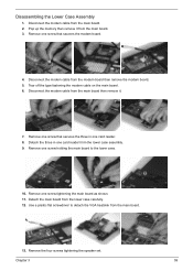
... main board from the main board. 2. Disconnect the modem cable from the lower case carefully. 12. Disconnect the modem cable from the main board. 13. Disassembling the Lower Case Assembly 1. Remove one card reader. 8. Chapter 3 59 Tear off the type fastening the modem cable on the main board. 6. Use a plastic flat...
... main board from the main board. 2. Disconnect the modem cable from the lower case carefully. 12. Disconnect the modem cable from the main board. 13. Disassembling the Lower Case Assembly 1. Remove one card reader. 8. Chapter 3 59 Tear off the type fastening the modem cable on the main board. 6. Use a plastic flat...
TravelMate 3200 Service Guide
Page 69
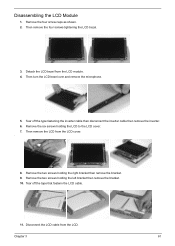
... bezel over and remove the microphone. 5. Tear off the type fastening the inverter cable then disconnect the inverter cable then remove the inverter. 6. Chapter 3 61 Disassembling the LCD Module 1. Then remove the LCD from the LCD. Disconnect the LCD cable from the LCD cover. . 8. Remove the two screws holding the LCD...
... bezel over and remove the microphone. 5. Tear off the type fastening the inverter cable then disconnect the inverter cable then remove the inverter. 6. Chapter 3 61 Disassembling the LCD Module 1. Then remove the LCD from the LCD. Disconnect the LCD cable from the LCD cover. . 8. Remove the two screws holding the LCD...

TravelMate 3200 Service Guide
Page 71
Detach the ODD bracket. Remove the two screws holding the HDD bracket on one side. 2. Chapter 3 63 Disconnect the HDD cable then remove it. Remove the two screws holding the ODD bracket. 2. Detach the hard disc drive from the HDD bracket. 4. Remove the two screws holding the HDD bracket on the other side. 3. Disassembling the Optical Drive Module 1. Disassembling the External Modules Disassembling the HDD Module 1.
Detach the ODD bracket. Remove the two screws holding the HDD bracket on one side. 2. Chapter 3 63 Disconnect the HDD cable then remove it. Remove the two screws holding the ODD bracket. 2. Detach the hard disc drive from the HDD bracket. 4. Remove the two screws holding the HDD bracket on the other side. 3. Disassembling the Optical Drive Module 1. Disassembling the External Modules Disassembling the HDD Module 1.

TravelMate 3200 Service Guide
Page 73
.... You can check the following: power cords are no obvious shorts or opens; Symptoms cannot be re-created (intermittent problems). Non-Acer products, prototype cards, or modified options can perform visual inspection before you fellow this model. If any power sources. 4. there are...symptom. No beep or error codes are no obviously burned or heated components; Chapter 4 Troubleshooting Use the following procedure as possible. 2. Disassemble and assemble the unit without any problem occurs, you can give false errors and invalid system responses. 1. POST detects an error and ...
.... You can check the following: power cords are no obvious shorts or opens; Symptoms cannot be re-created (intermittent problems). Non-Acer products, prototype cards, or modified options can perform visual inspection before you fellow this model. If any power sources. 4. there are...symptom. No beep or error codes are no obviously burned or heated components; Chapter 4 Troubleshooting Use the following procedure as possible. 2. Disassemble and assemble the unit without any problem occurs, you can give false errors and invalid system responses. 1. POST detects an error and ...
TravelMate 3200 User's Guide
Page 81
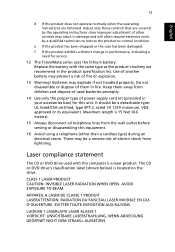
...classification label (shown below) is a laser product. It should be a remote risk of electric shock from the wall outlet before serving or disassembling this unit. APPAREIL A LASER DE CLASSE 1 PRODUIT LASERATTENTION: RADIATION DU FAISCEAU LASER INVISIBLE EN CAS D'OUVERTURE. There may result in the... promptly. 14 Use only the proper type of power supply cord set (provided in your accessories box) for service. 12 The TravelMate series uses the lithium battery. LUOKAN 1 LASERLAITE LASER KLASSE 1 VORSICHT: UNSICHTBARE LASERSTRAHLUNG, WENN ABDECKUNG GEÖFFNET NICHT DEM STRAHLL...
...classification label (shown below) is a laser product. It should be a remote risk of electric shock from the wall outlet before serving or disassembling this unit. APPAREIL A LASER DE CLASSE 1 PRODUIT LASERATTENTION: RADIATION DU FAISCEAU LASER INVISIBLE EN CAS D'OUVERTURE. There may result in the... promptly. 14 Use only the proper type of power supply cord set (provided in your accessories box) for service. 12 The TravelMate series uses the lithium battery. LUOKAN 1 LASERLAITE LASER KLASSE 1 VORSICHT: UNSICHTBARE LASERSTRAHLUNG, WENN ABDECKUNG GEÖFFNET NICHT DEM STRAHLL...

TravelMate 3200 User's Guide
Page 82
... LÁSER DE LA CLASE I STRÅLEN. Macrovision® copyright protection notice This product incorporates copyright protection technology that is prohibited. Reverse engineering or disassembly is protected by Macrovision Corporation. Nevertheless, some pixels may occasionally misfire or appear as black or red dots. Patent Nos. 4,631,603, 4,577,216, 4,819...
... LÁSER DE LA CLASE I STRÅLEN. Macrovision® copyright protection notice This product incorporates copyright protection technology that is prohibited. Reverse engineering or disassembly is protected by Macrovision Corporation. Nevertheless, some pixels may occasionally misfire or appear as black or red dots. Patent Nos. 4,631,603, 4,577,216, 4,819...


