TravelMate 3200 Service Guide
Page 7
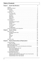
... Exit 46 BIOS Flash Utility 47 Chapter 3 Machine Disassembly and Replacement 49 General Information 50 Before You Begin 50 Disassembly Procedure Flowchart 51 Removing the Battery Pack 53 Removing the Wireless LAN Card/the HDD Module/the ODD Module /and the LCD module 54 Removing the Wireless LAN Card 54 Removing...
... Exit 46 BIOS Flash Utility 47 Chapter 3 Machine Disassembly and Replacement 49 General Information 50 Before You Begin 50 Disassembly Procedure Flowchart 51 Removing the Battery Pack 53 Removing the Wireless LAN Card/the HDD Module/the ODD Module /and the LCD module 54 Removing the Wireless LAN Card 54 Removing...
TravelMate 3200 Service Guide
Page 13
1 RJ11 2 1394 Connector 3 USB Connector 4 VGA Connector 5 Modem Cable Connector 8 LCD Connector 9 Internal MIC Connector 10 Battery Connector 11 FAN Connector 12 Line-out Connector 13 MIC Connector 14 Speaker Connector 15 DDR SO-DIMM (TOP) 16 Bluetooth Connector 17 MDC Connector 18 BIOS Socket 19 ODD Connector 20 Touchpad Connector 21 Keyboard Connector 22 QSB Cable Connector 23 RTC battery Connector 24 RJ45 Connector 25 Power Jack 26 Docking 27 3-in-1 Module Connector Chapter 1 5
1 RJ11 2 1394 Connector 3 USB Connector 4 VGA Connector 5 Modem Cable Connector 8 LCD Connector 9 Internal MIC Connector 10 Battery Connector 11 FAN Connector 12 Line-out Connector 13 MIC Connector 14 Speaker Connector 15 DDR SO-DIMM (TOP) 16 Bluetooth Connector 17 MDC Connector 18 BIOS Socket 19 ODD Connector 20 Touchpad Connector 21 Keyboard Connector 22 QSB Cable Connector 23 RTC battery Connector 24 RJ45 Connector 25 Power Jack 26 Docking 27 3-in-1 Module Connector Chapter 1 5
TravelMate 3200 Service Guide
Page 18
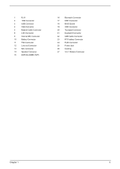
... stereo audio output. 2 Infrared port Interfaces with Bluetooth and Wireless features, respectively. NOTE: The Bluetooth and Wireless buttons and indicators only work on . 4 Battery indicator Lights when the battery is being charged 5 Bluetooth Indicates that (optional) Bluetooth is communications enabled. 6 Wireless Indicates status of wireless LAN communi- Note 10 Chapter 1 communication cation...
... stereo audio output. 2 Infrared port Interfaces with Bluetooth and Wireless features, respectively. NOTE: The Bluetooth and Wireless buttons and indicators only work on . 4 Battery indicator Lights when the battery is being charged 5 Bluetooth Indicates that (optional) Bluetooth is communications enabled. 6 Wireless Indicates status of wireless LAN communi- Note 10 Chapter 1 communication cation...
TravelMate 3200 Service Guide
Page 22
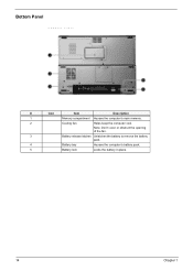
Bottom Panel Bottom view 4 # Item Description # Icon Item Description 1 Memory compartment Houses the computer's main memory. 2 Cooling fan Helps keep the computer cool. Note: Don't cover or obstruct the opening Note of the fan. 3 Battery release latches Unlatches the battery to remove the battery pack. 4 Battery bay Houses the computer's battery pack. 5 Battery lock Locks the battery in place. 14 Chapter 1
Bottom Panel Bottom view 4 # Item Description # Icon Item Description 1 Memory compartment Houses the computer's main memory. 2 Cooling fan Helps keep the computer cool. Note: Don't cover or obstruct the opening Note of the fan. 3 Battery release latches Unlatches the battery to remove the battery pack. 4 Battery bay Houses the computer's battery pack. 5 Battery lock Locks the battery in place. 14 Chapter 1
TravelMate 3200 Service Guide
Page 24
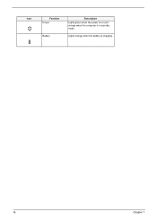
Icon Function Power Battery Description Lights green when the power is on and orange when the computer is charging. 16 Chapter 1 Lights orange when the battery is in standby mode.
Icon Function Power Battery Description Lights green when the power is on and orange when the computer is charging. 16 Chapter 1 Lights orange when the battery is in standby mode.
TravelMate 3200 Service Guide
Page 40
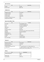
... 802.11 b+g PCMCIA Audio 3-in-1 card reader Keyboard Item Keyboard controller Total number of keypads Windows logo key Internal & external keyboard work simultaneously Battery Item Vendor & model name Battery Type Pack capacity 32 Left side IEEE 1394 TI PCI4510 Type-II One type-II Right panel Yes Yes Specification Specification Controller Intel...
... 802.11 b+g PCMCIA Audio 3-in-1 card reader Keyboard Item Keyboard controller Total number of keypads Windows logo key Internal & external keyboard work simultaneously Battery Item Vendor & model name Battery Type Pack capacity 32 Left side IEEE 1394 TI PCI4510 Type-II One type-II Right panel Yes Yes Specification Specification Controller Intel...
TravelMate 3200 Service Guide
Page 41
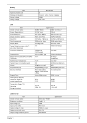
Battery Item Number of battery cell Package configuration Normal voltage Charge voltage Specification 6 3 cells in series, 2 series in parallel 14.4V 19+-0.2V LCD Item Vendor & model name Screen Diagonal (...
Battery Item Number of battery cell Package configuration Normal voltage Charge voltage Specification 6 3 cells in series, 2 series in parallel 14.4V 19+-0.2V LCD Item Vendor & model name Screen Diagonal (...
TravelMate 3200 Service Guide
Page 55
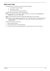
NOTE: Please use the Phlash. If the battery pack does not contain enough power to the bootable diskette. 3. Then boot the system from the bootable diskette. The Phlash utility has auto-execution function. ...
NOTE: Please use the Phlash. If the battery pack does not contain enough power to the bootable diskette. 3. Then boot the system from the bootable diskette. The Phlash utility has auto-execution function. ...
TravelMate 3200 Service Guide
Page 58
NOTE: TravelMate 3200 series product uses mylar or tape to fasten the FFC/FPC/connectors/cable, you may need to tear the tape or mylar before you fasten ... system. 3. Please also remember the screw location for each screw type. Turn off the power to secure bottom case and upper case assembly. Remove the battery pack. The screws vary in length. Unplug the AC adapter and all peripherals. 2. General Information Before You Begin Before proceeding with the disassembly procedure, make...
NOTE: TravelMate 3200 series product uses mylar or tape to fasten the FFC/FPC/connectors/cable, you may need to tear the tape or mylar before you fasten ... system. 3. Please also remember the screw location for each screw type. Turn off the power to secure bottom case and upper case assembly. Remove the battery pack. The screws vary in length. Unplug the AC adapter and all peripherals. 2. General Information Before You Begin Before proceeding with the disassembly procedure, make...
TravelMate 3200 Service Guide
Page 59
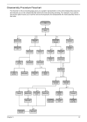
Start Battery K*2 Wireless cover Wireless LAN card E*2 K*2 F*1 DDR/HDD cover HDD module Memory G*2 L*2 left and right hinge cover assembly K*1 Left hinger cover K*2 Right hinge cover F*1 Keyboard K*5 Thermal ...
Start Battery K*2 Wireless cover Wireless LAN card E*2 K*2 F*1 DDR/HDD cover HDD module Memory G*2 L*2 left and right hinge cover assembly K*1 Left hinger cover K*2 Right hinge cover F*1 Keyboard K*5 Thermal ...
TravelMate 3200 Service Guide
Page 61
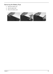
Release the battery lock. 2. Remove the battery pack. Chapter 3 53 Removing the Battery Pack 1. Slide the battery latch. 3.
Release the battery lock. 2. Remove the battery pack. Chapter 3 53 Removing the Battery Pack 1. Slide the battery latch. 3.
TravelMate 3200 Service Guide
Page 75
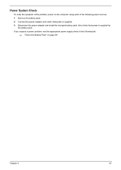
Connect the power adapter and check that power is supplied. 3. Disconnect the power adapter and install the charged battery pack; If you suspect a power problem, see the appropriate power supply check in the following power sources: 1. then check that power is supplied by the battery pack. Power System Check To verify the symptom of the following list: T "Check the Battery Pack" on the computer using each of the problem, power on page 68 Chapter 4 67 Remove the battery pack. 2.
Connect the power adapter and check that power is supplied. 3. Disconnect the power adapter and install the charged battery pack; If you suspect a power problem, see the appropriate power supply check in the following power sources: 1. then check that power is supplied by the battery pack. Power System Check To verify the symptom of the following list: T "Check the Battery Pack" on the computer using each of the problem, power on page 68 Chapter 4 67 Remove the battery pack. 2.
TravelMate 3200 Service Guide
Page 76
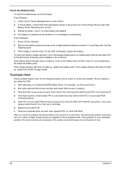
...switch board FPC is still less than 50% of time. 68 Chapter 4 Repeat the steps 1 and 2, for Current Power Source and Total Battery Power Remaining are necessary if the pointer movement stops in a short period of the total power remaining when installed in the computer. This symptom... is working. 3. Remove the battery pack and measure the voltage between battery terminals 1(+) and 6(ground). If the voltage is connected well, then check if the FCC on recharging or discharging. If ...
...switch board FPC is still less than 50% of time. 68 Chapter 4 Repeat the steps 1 and 2, for Current Power Source and Total Battery Power Remaining are necessary if the pointer movement stops in a short period of the total power remaining when installed in the computer. This symptom... is working. 3. Remove the battery pack and measure the voltage between battery terminals 1(+) and 6(ground). If the voltage is connected well, then check if the FCC on recharging or discharging. If ...
TravelMate 3200 Service Guide
Page 78
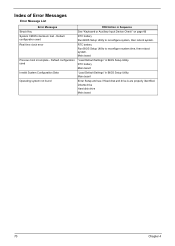
...Invalid System Configuration Data Operating system not found FRU/Action in Sequence See "Keyboard or Auxiliary Input Device Check" on page 66 RTC battery Run BIOS Setup Utility to reconfigure system time, then reboot system. Dikette drive Hard disk drive Main board 70 Chapter 4 Index of ... Messages Struck Key System CMOS checksum bad - Main board Enter Setup and see if fixed disk and drive A are properly identified. RTC battery Run BIOS Setup Utility to reconfigure system, then reboot system. Main board "Load Default Settings" in BIOS Setup Utility. Default configuration used ...
...Invalid System Configuration Data Operating system not found FRU/Action in Sequence See "Keyboard or Auxiliary Input Device Check" on page 66 RTC battery Run BIOS Setup Utility to reconfigure system time, then reboot system. Dikette drive Hard disk drive Main board 70 Chapter 4 Index of ... Messages Struck Key System CMOS checksum bad - Main board Enter Setup and see if fixed disk and drive A are properly identified. RTC battery Run BIOS Setup Utility to reconfigure system, then reboot system. Main board "Load Default Settings" in BIOS Setup Utility. Default configuration used ...
TravelMate 3200 Service Guide
Page 79
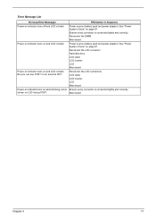
...LCD is blank. Error Message List No beep Error Messages FRU/Action in Sequence Power-on indicator turns off and LCD is blank. Power source (battery pack and power adapter.) See "Power System Check" on page 67 Ensure every connector is connected tightly and correctly. LCD cable LCD inverter LCD Main... indicator turns on and LCD is blank. Main board Chapter 4 71 Main board. But you can see POST on LCD during POST. Power source (battery pack and power adapter.) See "Power System Check" on page 67 Reconnect the LCD connector Hard disk drive LCD cable LCD inverter LCD Main board...
...LCD is blank. Error Message List No beep Error Messages FRU/Action in Sequence Power-on indicator turns off and LCD is blank. Power source (battery pack and power adapter.) See "Power System Check" on page 67 Ensure every connector is connected tightly and correctly. LCD cable LCD inverter LCD Main... indicator turns on and LCD is blank. Main board Chapter 4 71 Main board. But you can see POST on LCD during POST. Power source (battery pack and power adapter.) See "Power System Check" on page 67 Reconnect the LCD connector Hard disk drive LCD cable LCD inverter LCD Main board...
TravelMate 3200 Service Guide
Page 84
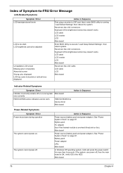
...to CRT port. Action in the HDD. See "Power System Check" on page 67. Main board Power source (battery pack and power adapter). Verify OS in Sequence Power source (battery pack and power adapter). Main board 76 Chapter 4 Action in Sequence First, plug a monitor to execute "Load Setup...Error Power shuts down during operation The system cannot power-on. Reconnect the LCD connectors. Keyboard (if the brightness function key doesn't work ). Battery pack AC adapter See if the thermal module is OK. Next, enter BIOS utility to -FRU Error Message LCD-Related Symptoms Symptom / Error LCD...
...to CRT port. Action in the HDD. See "Power System Check" on page 67. Main board Power source (battery pack and power adapter). Verify OS in Sequence Power source (battery pack and power adapter). Main board 76 Chapter 4 Action in Sequence First, plug a monitor to execute "Load Setup...Error Power shuts down during operation The system cannot power-on. Reconnect the LCD connectors. Keyboard (if the brightness function key doesn't work ). Battery pack AC adapter See if the thermal module is OK. Next, enter BIOS utility to -FRU Error Message LCD-Related Symptoms Symptom / Error LCD...
TravelMate 3200 Service Guide
Page 85
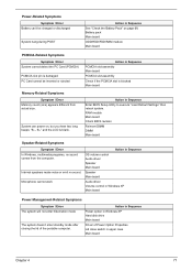
... enter hibernation mode The system doesn't enter standby mode after closing the lid of Power Option Properties Lid close switch in Sequence See "Check the Battery Pack" on , but you hear two long beeps: "B--, B--" and the LCD is damaged. System can 't be inserted or ejected Action in...Speaker Main board Speaker Main board Audio driver Volume control in Sequence Enter BIOS Setup Utility to execute "Load Default Settings" then reboot system. Battery pack Main board ODD/HDD/FDD/RAM module Main board PCMCIA-Related Symptoms Symptom / Error System cannot detect the PC Card (PCMCIA) PCMCIA...
... enter hibernation mode The system doesn't enter standby mode after closing the lid of Power Option Properties Lid close switch in Sequence See "Check the Battery Pack" on , but you hear two long beeps: "B--, B--" and the LCD is damaged. System can 't be inserted or ejected Action in...Speaker Main board Speaker Main board Audio driver Volume control in Sequence Enter BIOS Setup Utility to execute "Load Default Settings" then reboot system. Battery pack Main board ODD/HDD/FDD/RAM module Main board PCMCIA-Related Symptoms Symptom / Error System cannot detect the PC Card (PCMCIA) PCMCIA...
TravelMate 3200 Service Guide
Page 86
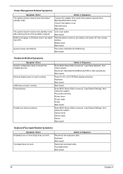
... more keys) does not work correctly. Touchpad board Main board 78 Chapter 4 Refresh battery (continue use battery until power off, then charge battery). External display does not work . USB does not work . Battery pack Main board System hangs intermittently. Run printer self-test. Action in Sequence The...system resumes from standby mode LCD cover switch after opening the lid of the portable computer. Check if the battery is low. Keyboard Main board Reconnect touchpad cable. Power Management-Related Symptoms Symptom / Error Action in Sequence Reconnect the keyboard ...
... more keys) does not work correctly. Touchpad board Main board 78 Chapter 4 Refresh battery (continue use battery until power off, then charge battery). External display does not work . USB does not work . Battery pack Main board System hangs intermittently. Run printer self-test. Action in Sequence The...system resumes from standby mode LCD cover switch after opening the lid of the portable computer. Check if the battery is low. Keyboard Main board Reconnect touchpad cable. Power Management-Related Symptoms Symptom / Error Action in Sequence Reconnect the keyboard ...
TravelMate 3200 Service Guide
Page 89
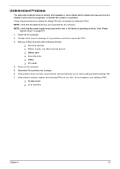
... that the power supply being used at the time of the following FRU one at a time. If the problem remains, replace the following devices: T Non-Acer devices T Printer, mouse, and other external devices T Battery pack T Hard disk drive T DIMM T PC Cards 4.
... that the power supply being used at the time of the following FRU one at a time. If the problem remains, replace the following devices: T Non-Acer devices T Printer, mouse, and other external devices T Battery pack T Hard disk drive T DIMM T PC Cards 4.
TravelMate 3200 Service Guide
Page 92
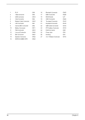
... 1394 Connector CN5 3 USB Connector CN12 4 VGA Connector CN2 5 Modem Cable Connector CN10 8 LCD Connector CN7 9 Internal MIC Connector CN4 10 Battery Connector CN11 11 FAN Connector CN15 12 Line-out Connector CN20 13 MIC Connector CN21 14 Speaker Connector CN22 15 DDR SO-DIMM (TOP) CN23 ... Socket U27 19 ODD Connector CN24 20 Touchpad Connector CN19 21 Keyboard Connector CN18 22 QSB Cable Connector CN16 23 RTC battery Connector CN14 24 RJ45 Connector CN9 25 Power Jack CN3 26 Docking CN1 27 3-in-1 Module Connector CN13 84 Chapter 5
... 1394 Connector CN5 3 USB Connector CN12 4 VGA Connector CN2 5 Modem Cable Connector CN10 8 LCD Connector CN7 9 Internal MIC Connector CN4 10 Battery Connector CN11 11 FAN Connector CN15 12 Line-out Connector CN20 13 MIC Connector CN21 14 Speaker Connector CN22 15 DDR SO-DIMM (TOP) CN23 ... Socket U27 19 ODD Connector CN24 20 Touchpad Connector CN19 21 Keyboard Connector CN18 22 QSB Cable Connector CN16 23 RTC battery Connector CN14 24 RJ45 Connector CN9 25 Power Jack CN3 26 Docking CN1 27 3-in-1 Module Connector CN13 84 Chapter 5


