Acer Aspire 7540 Service Guide
Page 7
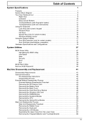
...Acer GridVista (dual-display compatible 18 Hardware Specifications and Configurations 19 System Utilities 27 BIOS Setup Utility 27 Navigating the BIOS Utility 28 Information 29 Main 31 Security 33 Boot 37 Exit 38 BIOS Flash Utility 39 Remove HDD Password 40 Machine Disassembly and Replacement 41 Disassembly... Requirements 41 General Information 42 Pre-disassembly Instructions 42 Disassembly Process 42 External Module Disassembly Process 43 External Modules Disassembly Flowchart 43 Removing the SD...
...Acer GridVista (dual-display compatible 18 Hardware Specifications and Configurations 19 System Utilities 27 BIOS Setup Utility 27 Navigating the BIOS Utility 28 Information 29 Main 31 Security 33 Boot 37 Exit 38 BIOS Flash Utility 39 Remove HDD Password 40 Machine Disassembly and Replacement 41 Disassembly... Requirements 41 General Information 42 Pre-disassembly Instructions 42 Disassembly Process 42 External Module Disassembly Process 43 External Modules Disassembly Flowchart 43 Removing the SD...
Acer Aspire 7540 Service Guide
Page 8
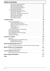
...Board 71 Removing the Bluetooth Board 72 Removing the Microphone Module 74 Removing the Main Board 75 LCD Module Disassembly Process 77 LCD Module Disassembly Flowchart 77 Removing the LCD Bezel 78 Removing the LCD panel with the Brackets 79 Removing the LCD Brackets... 105 BIOS Recovery by Crisis Disk 107 FRU (Field Replaceable Unit) List 111 Aspire 7736/7736Z/7336 Series and Aspire 7540 Series Exploded Diagram . . . . .112 Model Definition and Configuration 143 Aspire 7736/7736Z/7336 Series 144 Test Compatible Components 171 Microsoft® Windows® Vista Environment ...
...Board 71 Removing the Bluetooth Board 72 Removing the Microphone Module 74 Removing the Main Board 75 LCD Module Disassembly Process 77 LCD Module Disassembly Flowchart 77 Removing the LCD Bezel 78 Removing the LCD panel with the Brackets 79 Removing the LCD Brackets... 105 BIOS Recovery by Crisis Disk 107 FRU (Field Replaceable Unit) List 111 Aspire 7736/7736Z/7336 Series and Aspire 7540 Series Exploded Diagram . . . . .112 Model Definition and Configuration 143 Aspire 7736/7736Z/7336 Series 144 Test Compatible Components 171 Microsoft® Windows® Vista Environment ...

Acer Aspire 7540 Service Guide
Page 49
... Replacement This chapter contains step-by-step procedures on how to avoid mismatch when putting back the components. Disassembly Requirements To disassemble the computer, you need the following tools: • Wrist grounding strap and conductive mat for preventing electrostatic discharge • Flat screwdriver • Philips screwdriver • ...
... Replacement This chapter contains step-by-step procedures on how to avoid mismatch when putting back the components. Disassembly Requirements To disassemble the computer, you need the following tools: • Wrist grounding strap and conductive mat for preventing electrostatic discharge • Flat screwdriver • Philips screwdriver • ...

Acer Aspire 7540 Service Guide
Page 50
General Information Pre-disassembly Instructions Before proceeding with the disassembly procedure, make sure that order. Remove the battery pack. Turn off the power to any of the hardware ... the following stages: • External module disassembly • Main unit disassembly • LCD module disassembly The flowcharts provided in that you must first remove the keyboard, then disassemble the inside assembly frame in the succeeding disassembly sections illustrate the entire disassembly sequence. Disassembly Process The disassembly process is divided into the following : ...
General Information Pre-disassembly Instructions Before proceeding with the disassembly procedure, make sure that order. Remove the battery pack. Turn off the power to any of the hardware ... the following stages: • External module disassembly • Main unit disassembly • LCD module disassembly The flowcharts provided in that you must first remove the keyboard, then disassemble the inside assembly frame in the succeeding disassembly sections illustrate the entire disassembly sequence. Disassembly Process The disassembly process is divided into the following : ...
Acer Aspire 7540 Service Guide
Page 51
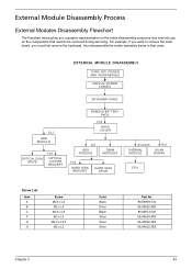
...example, if you want to remove the main board, you on the entire disassembly sequence and instructs you must first remove the keyboard, then disassemble the inside assembly frame in that need to be removed during servicing. EXTERNAL MODULE DISASSEMBLY TURN OFF POWER AND PERIPHERALS UNPLUG POWER CABLES SD DUMMY CARD Cx1 ODD...Part No. 86.00H59.734 86.9A552.4R0 86.00E12.536 86.9A554.4R0 86.9A536.3R5 86.9A552.3R0 Chapter 3 43 External Module Disassembly Process External Modules Disassembly Flowchart The flowchart below gives you a graphic representation on the components that order.
...example, if you want to remove the main board, you on the entire disassembly sequence and instructs you must first remove the keyboard, then disassemble the inside assembly frame in that need to be removed during servicing. EXTERNAL MODULE DISASSEMBLY TURN OFF POWER AND PERIPHERALS UNPLUG POWER CABLES SD DUMMY CARD Cx1 ODD...Part No. 86.00H59.734 86.9A552.4R0 86.00E12.536 86.9A554.4R0 86.9A536.3R5 86.9A552.3R0 Chapter 3 43 External Module Disassembly Process External Modules Disassembly Flowchart The flowchart below gives you a graphic representation on the components that order.
Acer Aspire 7540 Service Guide
Page 65
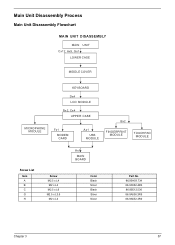
Main Unit Disassembly Process Main Unit Disassembly Flowchart MAIN UNIT DISASSEMBLY MAIN UNIT Cx12, Ax5, Gx1 LOWER CASE MIDDLE COVER MICROPHONE MODULE KEYBOARD Dx4 LCD MODULE Bx2, Cx4 UPPER CASE Fx1 MODEM CARD Ax1 USB MODULE Bx2 FINGERPRINT MODULE TOUCHPAD MODULE Screw List Item A B C G H Screw M2.5 x L4 M2 x L4 M2.5 x L6 M2.5 x L3.5 M2 x L3 Hx1 MAIN BOARD Color Black Silver Black Silver Silver Part No. 86.00H59.734 86.9A552.4R0 86.00E12.536 86.9A536.3R5 86.9A552.3R0 Chapter 3 57
Main Unit Disassembly Process Main Unit Disassembly Flowchart MAIN UNIT DISASSEMBLY MAIN UNIT Cx12, Ax5, Gx1 LOWER CASE MIDDLE COVER MICROPHONE MODULE KEYBOARD Dx4 LCD MODULE Bx2, Cx4 UPPER CASE Fx1 MODEM CARD Ax1 USB MODULE Bx2 FINGERPRINT MODULE TOUCHPAD MODULE Screw List Item A B C G H Screw M2.5 x L4 M2 x L4 M2.5 x L6 M2.5 x L3.5 M2 x L3 Hx1 MAIN BOARD Color Black Silver Black Silver Silver Part No. 86.00H59.734 86.9A552.4R0 86.00E12.536 86.9A536.3R5 86.9A552.3R0 Chapter 3 57
Acer Aspire 7540 Service Guide
Page 185
...BIOS Recovery by Crisis Disk 107 steps 107 BIOS Recovery Hotkey 107 BIOS Utility 27-39 Navigating 28 System Security 38 block diagram Aspire 7540 Series 5 Aspire 7738/7738G Series and 7735/7735G/ 7735Z/7735ZG Series 4 bluetooth board removing 72 button/indicator Bluetooth 11 Wireless LAN 11 buttons ...Disk creating 107 Crisis Recovery Disk 39 D DIMM module removing 51 E Environment Test 172 Euro 15 External CD-ROM Drive Check 86 External Module Disassembly Flowchart 43 F Fingerprint/button and touchpad boards removing 66 Flash Utility 39 FRU (Field Replaceable Unit) List 111 H Hard disk 21 HDD ...
...BIOS Recovery by Crisis Disk 107 steps 107 BIOS Recovery Hotkey 107 BIOS Utility 27-39 Navigating 28 System Security 38 block diagram Aspire 7540 Series 5 Aspire 7738/7738G Series and 7735/7735G/ 7735Z/7735ZG Series 4 bluetooth board removing 72 button/indicator Bluetooth 11 Wireless LAN 11 buttons ...Disk creating 107 Crisis Recovery Disk 39 D DIMM module removing 51 E Environment Test 172 Euro 15 External CD-ROM Drive Check 86 External Module Disassembly Flowchart 43 F Fingerprint/button and touchpad boards removing 66 Flash Utility 39 FRU (Field Replaceable Unit) List 111 H Hard disk 21 HDD ...

Acer Aspire 7540 Service Guide
Page 186
... Launch board removing 71 LCD bezel removing 78 LCD Brackets removing 81 LCD Module Disassembly Flowchart 77 LCD with the brackets removing 79 Locations connectors 103 M Main Screw List 42 Main Unit Disassembly Flowchart 57 media access on indicator 7 Memory Check 87 menu Boot 37 Exit 38... 88 Processor 19 S Screw List 42 System 4 Block Diagram 4 System Check Procedures 86 System Memory 19 System Utilities 17, 27 System utilities Acer GridVista 18 T Test Compatible Components 171 touchpad using 11 Touchpad Check 88 Troubleshooting 85 U Undetermined Problems 102 utility BIOS 27-39 V view bottom...
... Launch board removing 71 LCD bezel removing 78 LCD Brackets removing 81 LCD Module Disassembly Flowchart 77 LCD with the brackets removing 79 Locations connectors 103 M Main Screw List 42 Main Unit Disassembly Flowchart 57 media access on indicator 7 Memory Check 87 menu Boot 37 Exit 38... 88 Processor 19 S Screw List 42 System 4 Block Diagram 4 System Check Procedures 86 System Memory 19 System Utilities 17, 27 System utilities Acer GridVista 18 T Test Compatible Components 171 touchpad using 11 Touchpad Check 88 Troubleshooting 85 U Undetermined Problems 102 utility BIOS 27-39 V view bottom...


