
Acer Aspire 5810T, Aspire 5810TZ Notebook Series Start Guide
Page 4
webcam 2 Microphone Internal microphone for video communication. Top view # Icon Item Description 1 Acer Crystal Eye Web camera for sound recording. 3 Display screen Also called Liquid-Crystal Display (LCD), displays computer output (Configuration may vary by models). poster, let us show you around your computer as illustrated in the Just for Starters... English 4 Your Acer notebook tour After setting up your new Acer notebook.
webcam 2 Microphone Internal microphone for video communication. Top view # Icon Item Description 1 Acer Crystal Eye Web camera for sound recording. 3 Display screen Also called Liquid-Crystal Display (LCD), displays computer output (Configuration may vary by models). poster, let us show you around your computer as illustrated in the Just for Starters... English 4 Your Acer notebook tour After setting up your new Acer notebook.
Acer Aspire 5810T, Aspire 5810TZ Notebook Series Start Guide
Page 8
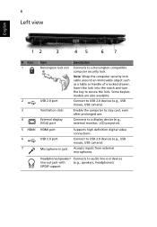
... definition digital video connections. Connect to USB 2.0 devices (e.g., USB mouse, USB camera). Accepts inputs from external microphones. Headphones/speaker/ Connects to a display device (e.g., external monitor, LCD projector). Connects to audio line-out devices line-out jack with (e.g., speakers, headphones). Insert the lock into the notch and turn the key to stay...
... definition digital video connections. Connect to USB 2.0 devices (e.g., USB mouse, USB camera). Accepts inputs from external microphones. Headphones/speaker/ Connects to a display device (e.g., external monitor, LCD projector). Connects to audio line-out devices line-out jack with (e.g., speakers, headphones). Insert the lock into the notch and turn the key to stay...
Aspire 5810TZ Service Guide
Page 7
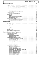
Table of Contents System Specifications 1 Features 1 Aspire 5810T/5810TZ/5410T System Block Diagram 3 Aspire 5810TG System Block Diagram 4 Your Acer Notebook tour 5 Right View 8 Indicators 11 Easy-Launch Buttons 1 Touchpad basics (with ... Keys 15 Special Key (only for certain models 15 Windows Mobility Center 16 Using the System Utilities 17 Acer GridVista (dual-display compatible 17 Hardware Specifications and Configurations 19 System Utilities 25 BIOS Setup Utility 25 Navigating ... Removing the Speaker Module 57 Removing the System Board 58 Removing the LCD Module 61 VII
Table of Contents System Specifications 1 Features 1 Aspire 5810T/5810TZ/5410T System Block Diagram 3 Aspire 5810TG System Block Diagram 4 Your Acer Notebook tour 5 Right View 8 Indicators 11 Easy-Launch Buttons 1 Touchpad basics (with ... Keys 15 Special Key (only for certain models 15 Windows Mobility Center 16 Using the System Utilities 17 Acer GridVista (dual-display compatible 17 Hardware Specifications and Configurations 19 System Utilities 25 BIOS Setup Utility 25 Navigating ... Removing the Speaker Module 57 Removing the System Board 58 Removing the LCD Module 61 VII
Aspire 5810TZ Service Guide
Page 8
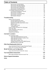
... Removing the Bluetooth Module 66 Removing the Card Reader Board 67 LCD Module Disassembly Process 69 LCD Module Disassembly Flowchart 69 Removing the LCD Bezel 70 Removing the LCD Panel Hinges 71 Removing the LCD Panel 73 Removing the Webcam 75 Troubleshooting 77 System Check Procedures...Intermittent Problems 89 Undetermined Problems 90 Connector Locations 91 Top and Bottom Views 91 Aspire 5810T/5810TZ/5410T Top View 91 Aspire 5810T/5810TZ/5410T Bottom View 92 Aspire 5810TG Top View 93 Aspire 5810TG Bottom View 94 Clearing Password Check and BIOS Recovery 95 BIOS Recovery ...
... Removing the Bluetooth Module 66 Removing the Card Reader Board 67 LCD Module Disassembly Process 69 LCD Module Disassembly Flowchart 69 Removing the LCD Bezel 70 Removing the LCD Panel Hinges 71 Removing the LCD Panel 73 Removing the Webcam 75 Troubleshooting 77 System Check Procedures...Intermittent Problems 89 Undetermined Problems 90 Connector Locations 91 Top and Bottom Views 91 Aspire 5810T/5810TZ/5410T Top View 91 Aspire 5810T/5810TZ/5410T Bottom View 92 Aspire 5810TG Top View 93 Aspire 5810TG Bottom View 94 Clearing Password Check and BIOS Recovery 95 BIOS Recovery ...
Aspire 5810TZ Service Guide
Page 13
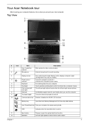
... for three-step data backup. Chapter 1 5 webcam 2 Microphone Internal microphone for video communication. Top View # Icon Item Description 1 Acer Crystal Eye Web camera for sound recording. 3 Display screen Also called Liquid-Crystal Display (LCD), displays computer output (Configuration may vary by models). 4 Power button / Turns the computer on and off . / indicator Indicates...
... for three-step data backup. Chapter 1 5 webcam 2 Microphone Internal microphone for video communication. Top View # Icon Item Description 1 Acer Crystal Eye Web camera for sound recording. 3 Display screen Also called Liquid-Crystal Display (LCD), displays computer output (Configuration may vary by models). 4 Power button / Turns the computer on and off . / indicator Indicates...
Aspire 5810TZ Service Guide
Page 15
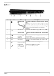
... USB 2.0 devices (e.g., USB mouse, USB camera). Chapter 1 7 USB 2.0 port Connect to audio line-out devices (e.g., speakers, headphones). USB 2.0 port Connect to a display device (e.g., external monitor, LCD projector). External display (VGA) port Connects to USB 2.0 devices (e.g., USB mouse, USB camera). Ventilation slots Enable the computer to a Kensington-compatible computer security lock. Left...
... USB 2.0 devices (e.g., USB mouse, USB camera). Chapter 1 7 USB 2.0 port Connect to audio line-out devices (e.g., speakers, headphones). USB 2.0 port Connect to a display device (e.g., external monitor, LCD projector). External display (VGA) port Connects to USB 2.0 devices (e.g., USB mouse, USB camera). Ventilation slots Enable the computer to a Kensington-compatible computer security lock. Left...

Aspire 5810TZ Service Guide
Page 32
... shutdown. Individual devices such as the CPU and hard disc may be power managed in the system are turned off the whole system. 24 Chapter 1 LCD 15.6" inch Item Vendor & model name Screen Diagonal (mm) Display resolution (pixels) Pixel Pitch Pixel Arrangement Display Mode Typical White Luminance (NIT) also called Hibernation...
... shutdown. Individual devices such as the CPU and hard disc may be power managed in the system are turned off the whole system. 24 Chapter 1 LCD 15.6" inch Item Vendor & model name Screen Diagonal (mm) Display resolution (pixels) Pixel Pitch Pixel Arrangement Display Mode Typical White Luminance (NIT) also called Hibernation...

Aspire 5810TZ Service Guide
Page 48
... following : 1. For example, if you want to remove the main board, you do the following stages: • External module disassembly • Main unit disassembly • LCD module disassembly The flowcharts provided in that you must first remove the keyboard, then disassemble the inside the card slot. Remove any of the sequence...
... following : 1. For example, if you want to remove the main board, you do the following stages: • External module disassembly • Main unit disassembly • LCD module disassembly The flowcharts provided in that you must first remove the keyboard, then disassemble the inside the card slot. Remove any of the sequence...

Aspire 5810TZ Service Guide
Page 57
Main Unit Disassembly Process Main Unit Disassembly Flowchart MAIN UNIT DISASSEMBLY MAIN UNIT KEYBOARD B x 1 WLAN BOARD MODULE A x 16 UPPER CASE Ax2 LCD MODULE B x 2 SYSTEM BOARD B x 2 FINGERPRINT MODULE B x 1 MINI BOARD CRT BOARD THERMAL MODULE TOUCHPAD POWER BUTTON MODULE BOARD BLUETOOTH MODULE B x 2 CARD READER BOARD Screw List Item A B Screw M2.5 x L6 M2 x L4 Color Black Silver Part No. 86.00E69.736 86.00E13.524 Chapter 3 49
Main Unit Disassembly Process Main Unit Disassembly Flowchart MAIN UNIT DISASSEMBLY MAIN UNIT KEYBOARD B x 1 WLAN BOARD MODULE A x 16 UPPER CASE Ax2 LCD MODULE B x 2 SYSTEM BOARD B x 2 FINGERPRINT MODULE B x 1 MINI BOARD CRT BOARD THERMAL MODULE TOUCHPAD POWER BUTTON MODULE BOARD BLUETOOTH MODULE B x 2 CARD READER BOARD Screw List Item A B Screw M2.5 x L6 M2 x L4 Color Black Silver Part No. 86.00E69.736 86.00E13.524 Chapter 3 49
Aspire 5810TZ Service Guide
Page 58
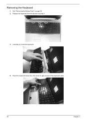
Release the keyboard from the latches securing it. 3. See "Removing the Battery Pack" on page 42. 2. Carefully pry loose the keyboard. 4. Removing the Keyboard 1. Place the keyboard below the LCD screen to gain access to the keyboard cable. 50 Chapter 3
Release the keyboard from the latches securing it. 3. See "Removing the Battery Pack" on page 42. 2. Carefully pry loose the keyboard. 4. Removing the Keyboard 1. Place the keyboard below the LCD screen to gain access to the keyboard cable. 50 Chapter 3

Aspire 5810TZ Service Guide
Page 68
15. Remove the two screws (B) securing the system board and the mini board.. Step 1 Size (Quantity) M2 x L4 (1) 17. Carefully remove the main board. Disconnect the LCD cable from the LCD1 connector on the system board. 16. Black Color Torque 1.6 kgf-cm 60 Chapter 3
15. Remove the two screws (B) securing the system board and the mini board.. Step 1 Size (Quantity) M2 x L4 (1) 17. Carefully remove the main board. Disconnect the LCD cable from the LCD1 connector on the system board. 16. Black Color Torque 1.6 kgf-cm 60 Chapter 3
Aspire 5810TZ Service Guide
Page 69
... 1. See "Removing the Lower Cover" on page 44. 5. Release the wireless antenna cables from the left and right hinge of the LCD module. See "Removing the Optical Drive Module" on page 43. 4. See "Removing the RTC Battery" on page 42. 2. See "Removing the Battery Pack" on page ...
... 1. See "Removing the Lower Cover" on page 44. 5. Release the wireless antenna cables from the left and right hinge of the LCD module. See "Removing the Optical Drive Module" on page 43. 4. See "Removing the RTC Battery" on page 42. 2. See "Removing the Battery Pack" on page ...
Aspire 5810TZ Service Guide
Page 70
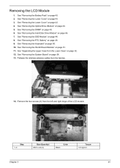
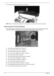
NOTE: When connecting the cable back to use the UMA model (for Aspire 5810TG) looks like the picture below: 1. See "Removing the Battery Pack" on page 48. 9. See "Removing the RTC Battery" on page 42. 2. See "Removing the .... 6. See "Removing the DIMM" on page 43. 4. See "Removing the System Board" on page 44. 5. Carefully remove the LCD module from the Lower Case" on page 51. 11. The discrete version (for Aspire 5810T/5810TZ/5410T). See "Removing the Optical Drive Module" on page 58. 62 Chapter 3 See "Removing the WLAN Board Module...
NOTE: When connecting the cable back to use the UMA model (for Aspire 5810TG) looks like the picture below: 1. See "Removing the Battery Pack" on page 48. 9. See "Removing the RTC Battery" on page 42. 2. See "Removing the .... 6. See "Removing the DIMM" on page 43. 4. See "Removing the System Board" on page 44. 5. Carefully remove the LCD module from the Lower Case" on page 51. 11. The discrete version (for Aspire 5810T/5810TZ/5410T). See "Removing the Optical Drive Module" on page 58. 62 Chapter 3 See "Removing the WLAN Board Module...

Aspire 5810TZ Service Guide
Page 78
..." on page 42. 2. See "Removing the SSD Module" on page 48. 9. See "Separating the Upper Case from the LCD bezel. 15. See "Removing the RTC Battery" on page 48. 8. Removing the LCD Bezel 1. See "Removing the WLAN Board Module" on page 43. 3. Step 1~4 Size (Quantity) M2.5 x L6 (4)... Silver Color 70 Torque 3.0 kgf-cm Chapter 3 Remove the four rubber screw covers from the Lower Case" on the LCD module as shown. See "Removing the Lower Cover" on page 51. 11. See "Removing the Lower Cover" on page 44. 5. See "Removing the Optical...
..." on page 42. 2. See "Removing the SSD Module" on page 48. 9. See "Separating the Upper Case from the LCD bezel. 15. See "Removing the RTC Battery" on page 48. 8. Removing the LCD Bezel 1. See "Removing the WLAN Board Module" on page 43. 3. Step 1~4 Size (Quantity) M2.5 x L6 (4)... Silver Color 70 Torque 3.0 kgf-cm Chapter 3 Remove the four rubber screw covers from the Lower Case" on the LCD module as shown. See "Removing the Lower Cover" on page 51. 11. See "Removing the Lower Cover" on page 44. 5. See "Removing the Optical...
Aspire 5810TZ Service Guide
Page 79
... page 46. 7. See "Removing the Hard Disk Drive Module" on page 44. 5. See "Separating the Upper Case from the LCD panel. See "Removing the LCD Module" on page 43. 4. Carefully pry open the LCD bezel and and remove the bezel from the Lower Case" on page 70. See "Removing the Lower Cover" on... page 61. 14. 16. See "Removing the RTC Battery" on page 48. 8. See "Removing the SSD Module" on page 48. 9. See "Removing the LCD Bezel" on page 52. 12. Chapter 3 71 Removing the...
... page 46. 7. See "Removing the Hard Disk Drive Module" on page 44. 5. See "Separating the Upper Case from the LCD panel. See "Removing the LCD Module" on page 43. 4. Carefully pry open the LCD bezel and and remove the bezel from the Lower Case" on page 70. See "Removing the Lower Cover" on... page 61. 14. 16. See "Removing the RTC Battery" on page 48. 8. See "Removing the SSD Module" on page 48. 9. See "Removing the LCD Bezel" on page 52. 12. Chapter 3 71 Removing the...
Aspire 5810TZ Service Guide
Page 81
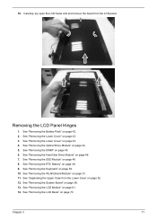
...45. 6. See "Removing the DIMM" on page 44. 5. See "Removing the WLAN Board Module" on page 61. 14. See "Removing the LCD Module" on page 51. 11. See "Removing the LCD Panel Hinges" on page 48. 8. See "Removing the SSD Module" on page 71. See "Removing the RTC Battery" on page 50.... Chapter 3 73 See "Removing the Keyboard" on page 48. 9. See "Separating the Upper Case from the Lower Case" on page 70. 15. See "Removing the LCD Bezel" on page 52. 12. See "Removing the Battery Pack" on page 43. 3. See "Removing the Lower Cover" on page 42. 2. See "Removing the Lower...
...45. 6. See "Removing the DIMM" on page 44. 5. See "Removing the WLAN Board Module" on page 61. 14. See "Removing the LCD Module" on page 51. 11. See "Removing the LCD Panel Hinges" on page 48. 8. See "Removing the SSD Module" on page 71. See "Removing the RTC Battery" on page 50.... Chapter 3 73 See "Removing the Keyboard" on page 48. 9. See "Separating the Upper Case from the Lower Case" on page 70. 15. See "Removing the LCD Bezel" on page 52. 12. See "Removing the Battery Pack" on page 43. 3. See "Removing the Lower Cover" on page 42. 2. See "Removing the Lower...

Aspire 5810TZ Service Guide
Page 82
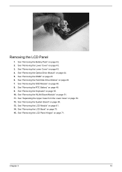
Step 1~4 Size (Quantity) M2 x L2.5 (4) Silver Color Torque 1.6 kgf-cm 17. Detach the acetic tape on the LCD cable. 74 Chapter 3 16. Remove the four screws (E) securing the LCD panel to the LCD cable. 18. Carefully lift up the LCD panel and turn it over to gain access to the back cover.
Step 1~4 Size (Quantity) M2 x L2.5 (4) Silver Color Torque 1.6 kgf-cm 17. Detach the acetic tape on the LCD cable. 74 Chapter 3 16. Remove the four screws (E) securing the LCD panel to the LCD cable. 18. Carefully lift up the LCD panel and turn it over to gain access to the back cover.

Aspire 5810TZ Service Guide
Page 83
...on page 46. 7. See "Removing the Hard Disk Drive Module" on page 43. 3. See "Removing the WLAN Board Module" on page 70. See "Removing the LCD Bezel" on page 51. 11. See "Removing the Battery Pack" on page 48. 9. See "Removing the RTC Battery" on page 42. 2. 19. See "... back cover. Chapter 3 75 See "Removing the SSD Module" on page 58. 13. See "Removing the System Board" on page 48. 8. Remove the LCD panel from the LCD panel. 20. Removing the Webcam 1. See "Removing the Lower Cover" on page 44. 5. See "Removing the Optical Drive Module" on page 43. 4....
...on page 46. 7. See "Removing the Hard Disk Drive Module" on page 43. 3. See "Removing the WLAN Board Module" on page 70. See "Removing the LCD Bezel" on page 51. 11. See "Removing the Battery Pack" on page 48. 9. See "Removing the RTC Battery" on page 42. 2. 19. See "... back cover. Chapter 3 75 See "Removing the SSD Module" on page 58. 13. See "Removing the System Board" on page 48. 8. Remove the LCD panel from the LCD panel. 20. Removing the Webcam 1. See "Removing the Lower Cover" on page 44. 5. See "Removing the Optical Drive Module" on page 43. 4....
Aspire 5810TZ Service Guide
Page 85
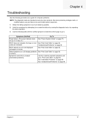
... "Undetermined Problems" on page 90 See "Post Code Table" on page 82. No beep or error codes are intended to test only Acer products. LCD display problems or others). See "Post Code Table" on page 82. See "Intermittent Problems" on page 90. Symptoms cannot be re-... as a guide for computer problems. NOTE: The diagnostic tests are indicated. Chapter 4 77 See "Undetermined Problems" on page 89. Non-Acer products, prototype cards, or modified options can give false errors and invalid system responses. 1. Chapter 4 Troubleshooting Use the following table with the...
... "Undetermined Problems" on page 90 See "Post Code Table" on page 82. No beep or error codes are intended to test only Acer products. LCD display problems or others). See "Post Code Table" on page 82. See "Intermittent Problems" on page 90. Symptoms cannot be re-... as a guide for computer problems. NOTE: The diagnostic tests are indicated. Chapter 4 77 See "Undetermined Problems" on page 89. Non-Acer products, prototype cards, or modified options can give false errors and invalid system responses. 1. Chapter 4 Troubleshooting Use the following table with the...
Aspire 5810TZ Service Guide
Page 93
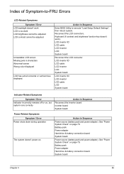
See "Power System Check" on page 79. LCD inverter ID LCD cable LCD inverter LCD System board Reconnect the LCD connector LCD inverter ID LCD cable LCD inverter LCD System board LCD inverter ID LCD inverter LCD cable LCD System board Indicator-Related Symptoms Symptom / Error Indicator incorrectly remains off or on . Action in Sequence Reconnect the inverter board Inverter board System board Power...
See "Power System Check" on page 79. LCD inverter ID LCD cable LCD inverter LCD System board Reconnect the LCD connector LCD inverter ID LCD cable LCD inverter LCD System board LCD inverter ID LCD inverter LCD cable LCD System board Indicator-Related Symptoms Symptom / Error Indicator incorrectly remains off or on . Action in Sequence Reconnect the inverter board Inverter board System board Power...


