Aspire 5810TZ Service Guide
Page 7
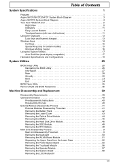
Table of Contents System Specifications 1 Features 1 Aspire 5810T/5810TZ/5410T System Block Diagram 3 Aspire 5810TG System Block Diagram 4 Your Acer Notebook tour 5 Right View 8 Indicators 11 Easy-Launch Buttons 1 Touchpad basics (with two-click buttons... Flash Utility 35 Remove HDD and BIOS Passwords 36 Machine Disassembly and Replacement 39 Disassembly Requirements 39 General Information 40 Pre-disassembly Instructions 40 Disassembly Process 40 External Module Disassembly Process 41 External Modules Disassembly Flowchart 41 Removing the Battery Pack 42 Removing the Lower ...
Table of Contents System Specifications 1 Features 1 Aspire 5810T/5810TZ/5410T System Block Diagram 3 Aspire 5810TG System Block Diagram 4 Your Acer Notebook tour 5 Right View 8 Indicators 11 Easy-Launch Buttons 1 Touchpad basics (with two-click buttons... Flash Utility 35 Remove HDD and BIOS Passwords 36 Machine Disassembly and Replacement 39 Disassembly Requirements 39 General Information 40 Pre-disassembly Instructions 40 Disassembly Process 40 External Module Disassembly Process 41 External Modules Disassembly Flowchart 41 Removing the Battery Pack 42 Removing the Lower ...
Aspire 5810TZ Service Guide
Page 8
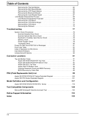
... 64 Removing the CRT Board Module 65 Removing the Bluetooth Module 66 Removing the Card Reader Board 67 LCD Module Disassembly Process 69 LCD Module Disassembly Flowchart 69 Removing the LCD Bezel 70 Removing the LCD Panel Hinges 71 Removing the LCD Panel 73 Removing the ... 85 Intermittent Problems 89 Undetermined Problems 90 Connector Locations 91 Top and Bottom Views 91 Aspire 5810T/5810TZ/5410T Top View 91 Aspire 5810T/5810TZ/5410T Bottom View 92 Aspire 5810TG Top View 93 Aspire 5810TG Bottom View 94 Clearing Password Check and BIOS Recovery 95 BIOS Recovery by Crisis ...
... 64 Removing the CRT Board Module 65 Removing the Bluetooth Module 66 Removing the Card Reader Board 67 LCD Module Disassembly Process 69 LCD Module Disassembly Flowchart 69 Removing the LCD Bezel 70 Removing the LCD Panel Hinges 71 Removing the LCD Panel 73 Removing the ... 85 Intermittent Problems 89 Undetermined Problems 90 Connector Locations 91 Top and Bottom Views 91 Aspire 5810T/5810TZ/5410T Top View 91 Aspire 5810T/5810TZ/5410T Bottom View 92 Aspire 5810TG Top View 93 Aspire 5810TG Bottom View 94 Clearing Password Check and BIOS Recovery 95 BIOS Recovery by Crisis ...

Aspire 5810TZ Service Guide
Page 47
... screwdriver • Plastic tweezers NOTE: The screws for maintenance and troubleshooting. During the disassembly process, group the screws with the corresponding components to disassemble the notebook computer for the different components vary in size. Chapter 3 39 Chapter 3 Machine Disassembly and Replacement This chapter contains step-by-step procedures on how to avoid mismatch...
... screwdriver • Plastic tweezers NOTE: The screws for maintenance and troubleshooting. During the disassembly process, group the screws with the corresponding components to disassemble the notebook computer for the different components vary in size. Chapter 3 39 Chapter 3 Machine Disassembly and Replacement This chapter contains step-by-step procedures on how to avoid mismatch...

Aspire 5810TZ Service Guide
Page 48
... signal cables from the system. 3. Turn off the power to any dummy card that might still be inside assembly frame in the succeeding disassembly sections illustrate the entire disassembly sequence. Main Screw List Item A B C D E F G H Screw M2.5 x L6 M2 x L4 M3 x L4 M2 x L3 M2 x L2.5 M2...For example, if you want to remove the main board, you do the following stages: • External module disassembly • Main unit disassembly • LCD module disassembly The flowcharts provided in that order. Unplug the AC adapter and all peripherals. 2. Remove any of the hardware ...
... signal cables from the system. 3. Turn off the power to any dummy card that might still be inside assembly frame in the succeeding disassembly sections illustrate the entire disassembly sequence. Main Screw List Item A B C D E F G H Screw M2.5 x L6 M2 x L4 M3 x L4 M2 x L3 M2 x L2.5 M2...For example, if you want to remove the main board, you do the following stages: • External module disassembly • Main unit disassembly • LCD module disassembly The flowcharts provided in that order. Unplug the AC adapter and all peripherals. 2. Remove any of the hardware ...
Aspire 5810TZ Service Guide
Page 49
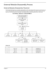
...if you want to remove the main board, you on the entire disassembly sequence and instructs you must first remove the keyboard, then disassemble the inside assembly frame in that need to be removed during servicing. EXTERNAL MODULE DISASSEMBLY TURN OFF POWER AND PERIPHERALS UNPLUG POWER CABLES REMOVE BATTERY PACK Hx4 ...x L3 M2.5 x L11 Black Silver Silver Black 86.00E69.736 86.9A524.4R0 86.9A552.3R0 86.1A353.110 Chapter 3 41 External Module Disassembly Process External Modules Disassembly Flowchart The flowchart below gives you a graphic representation on the components that order.
...if you want to remove the main board, you on the entire disassembly sequence and instructs you must first remove the keyboard, then disassemble the inside assembly frame in that need to be removed during servicing. EXTERNAL MODULE DISASSEMBLY TURN OFF POWER AND PERIPHERALS UNPLUG POWER CABLES REMOVE BATTERY PACK Hx4 ...x L3 M2.5 x L11 Black Silver Silver Black 86.00E69.736 86.9A524.4R0 86.9A552.3R0 86.1A353.110 Chapter 3 41 External Module Disassembly Process External Modules Disassembly Flowchart The flowchart below gives you a graphic representation on the components that order.

Aspire 5810TZ Service Guide
Page 57
Main Unit Disassembly Process Main Unit Disassembly Flowchart MAIN UNIT DISASSEMBLY MAIN UNIT KEYBOARD B x 1 WLAN BOARD MODULE A x 16 UPPER CASE Ax2 LCD MODULE B x 2 SYSTEM BOARD B x 2 FINGERPRINT MODULE B x 1 MINI BOARD CRT BOARD THERMAL MODULE TOUCHPAD POWER BUTTON MODULE BOARD BLUETOOTH MODULE B x 2 CARD READER BOARD Screw List Item A B Screw M2.5 x L6 M2 x L4 Color Black Silver Part No. 86.00E69.736 86.00E13.524 Chapter 3 49
Main Unit Disassembly Process Main Unit Disassembly Flowchart MAIN UNIT DISASSEMBLY MAIN UNIT KEYBOARD B x 1 WLAN BOARD MODULE A x 16 UPPER CASE Ax2 LCD MODULE B x 2 SYSTEM BOARD B x 2 FINGERPRINT MODULE B x 1 MINI BOARD CRT BOARD THERMAL MODULE TOUCHPAD POWER BUTTON MODULE BOARD BLUETOOTH MODULE B x 2 CARD READER BOARD Screw List Item A B Screw M2.5 x L6 M2 x L4 Color Black Silver Part No. 86.00E69.736 86.00E13.524 Chapter 3 49
Aspire 5810TZ Service Guide
Page 143
... Crisis Disk 96 steps 96 BIOS Recovery Hotkey 96 BIOS Utility 25-35 Flash 35 Navigating 26 Button eject 5 button / indicator 5 button/indicator Acer PowerSmart 5 Backup 5 C Clearing BIOS Password steps 96 compartment memory 10 Connector Locations 91 cooling fan 10 Core logic 19 CPU core voltage 19...81 Euro 15 Euro symbol 15 External CD-ROM Drive Check 78 External Diskette Drive Check 78 F Features 1 Flowchart External Module Disassembly 41 LCD Module Disassembly 69 Main Unit Disassembly 49 FRU (Field Replaceable Unit) List 99 H Hard disk 21 hard disk drive module removing 46 HDD 21 Hot key ...
... Crisis Disk 96 steps 96 BIOS Recovery Hotkey 96 BIOS Utility 25-35 Flash 35 Navigating 26 Button eject 5 button / indicator 5 button/indicator Acer PowerSmart 5 Backup 5 C Clearing BIOS Password steps 96 compartment memory 10 Connector Locations 91 cooling fan 10 Core logic 19 CPU core voltage 19...81 Euro 15 Euro symbol 15 External CD-ROM Drive Check 78 External Diskette Drive Check 78 F Features 1 Flowchart External Module Disassembly 41 LCD Module Disassembly 69 Main Unit Disassembly 49 FRU (Field Replaceable Unit) List 99 H Hard disk 21 hard disk drive module removing 46 HDD 21 Hot key ...


