Aspire 5510 Service Guide
Page 6
... 44 Removing the HDD Module/the Memory and the Wireless LAN Card/the Thermal Module and the CPU/ODD Module and LCD Module 45 Disassembling the Main Unit 49 Disassembling the LCD Module 53 Disassembling the External Modules 55 Chapter 4 Troubleshooting 56 System Check Procedures 57 Power-On Self-Test (POST) Error...
... 44 Removing the HDD Module/the Memory and the Wireless LAN Card/the Thermal Module and the CPU/ODD Module and LCD Module 45 Disassembling the Main Unit 49 Disassembling the LCD Module 53 Disassembling the External Modules 55 Chapter 4 Troubleshooting 56 System Check Procedures 57 Power-On Self-Test (POST) Error...
Aspire 5510 Service Guide
Page 7
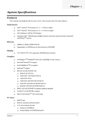
...//60 Hz T 800x600: 200/160/120/100/85/75/60 Hz MPEG-1/24 and DVD/HDTV hardware-assisted capability S-video/TV-out (NTSC/PAL) support Aspire CinemaVisionTM video technology TV Tuner T T T MiniPCI type Reserve necessary thermal solution 3 TV tuner modules at lease T Analog w/ HW MPEG2 T Analog+Digital w/ HS MPEG2(Hybrid)...Wi-Fi CERTIFIEDTM solution Memory T T 256MB or 512MB of DDRII 400/533 Upgradeable to 2GB Memory by Dual channels of SODIMM Display T 15.4" WXGA+TFT LCD, supporting 1280x800 pixel resolution Graphics T T T T T T T T ATI MOBILITYTM RADEON® X700 with the user in mind.
...//60 Hz T 800x600: 200/160/120/100/85/75/60 Hz MPEG-1/24 and DVD/HDTV hardware-assisted capability S-video/TV-out (NTSC/PAL) support Aspire CinemaVisionTM video technology TV Tuner T T T MiniPCI type Reserve necessary thermal solution 3 TV tuner modules at lease T Analog w/ HW MPEG2 T Analog+Digital w/ HS MPEG2(Hybrid)...Wi-Fi CERTIFIEDTM solution Memory T T 256MB or 512MB of DDRII 400/533 Upgradeable to 2GB Memory by Dual channels of SODIMM Display T 15.4" WXGA+TFT LCD, supporting 1280x800 pixel resolution Graphics T T T T T T T T ATI MOBILITYTM RADEON® X700 with the user in mind.
Aspire 5510 Service Guide
Page 8
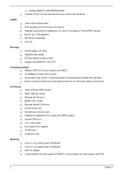
... 802.11 a/b/g dual-band tri-mode Wireless with Mini-PCI interface T Built-in 2 Antenna (which has to be placed on the top of LCD on the sides of LCD latch) I/O Ports T T T T T T T T T T T T T Three external USB 2.0 ports IEEE 1394 port (4-pin) Ethernet (RJ-45) port Modem (RJ-11) port External display (VGA) port S-video...
... 802.11 a/b/g dual-band tri-mode Wireless with Mini-PCI interface T Built-in 2 Antenna (which has to be placed on the top of LCD on the sides of LCD latch) I/O Ports T T T T T T T T T T T T T Three external USB 2.0 ports IEEE 1394 port (4-pin) Ethernet (RJ-45) port Modem (RJ-11) port External display (VGA) port S-video...
Aspire 5510 Service Guide
Page 10
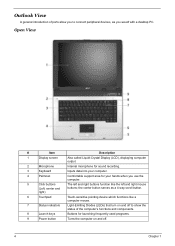
... on and off. 4 Chapter 1 the center button serves as a 4-way scroll button. Open View # Item # Item Description Description 1 Display screen Also called Liquid-Crystal Display (LCD), displaying computer output. 2 Microphone Internal microphone for sound recording. 3 Keyboard Inputs data into your hands when you to connect peripheral devicesJ,uasst fyooruSwtaorutledrsw..it.h a desktop...
... on and off. 4 Chapter 1 the center button serves as a 4-way scroll button. Open View # Item # Item Description Description 1 Display screen Also called Liquid-Crystal Display (LCD), displaying computer output. 2 Microphone Internal microphone for sound recording. 3 Keyboard Inputs data into your hands when you to connect peripheral devicesJ,uasst fyooruSwtaorutledrsw..it.h a desktop...
Aspire 5510 Service Guide
Page 14
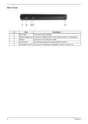
Rear View # Item Description 1 DC-in jack Connects to an AC adapter. 2 External display port Connects to a display device (e.g., external monitor, LCD projector). 3 RF jack Connects to a TV antenna or cable. 4 AV input port Accepts input signals from audiovisual(AV) devices. 5 Kensington lock slot Connects to a Kensington-compatible computer security lock. 8 Chapter 1
Rear View # Item Description 1 DC-in jack Connects to an AC adapter. 2 External display port Connects to a display device (e.g., external monitor, LCD projector). 3 RF jack Connects to a TV antenna or cable. 4 AV input port Accepts input signals from audiovisual(AV) devices. 5 Kensington lock slot Connects to a Kensington-compatible computer security lock. 8 Chapter 1
Aspire 5510 Service Guide
Page 30
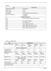
... (Note 1) B/I : Battery-In Pin TS : Connect to Thermister SMD : SMBus data interface I/O pin SMC : SMBus clock interface I/O pin GND : Battery Negative Terminal LCD :15.4" WXGA LCD Item Vendor & model name LCD display area (diagonal, inch) Display technology Resolution Specification CMO N154I1-L09 LPL LP154W01A5 Hitachi TX39D85V C1FAA Mechanical Specifications 15.4" 15.4" 15.4" Samsung...
... (Note 1) B/I : Battery-In Pin TS : Connect to Thermister SMD : SMBus data interface I/O pin SMC : SMBus clock interface I/O pin GND : Battery Negative Terminal LCD :15.4" WXGA LCD Item Vendor & model name LCD display area (diagonal, inch) Display technology Resolution Specification CMO N154I1-L09 LPL LP154W01A5 Hitachi TX39D85V C1FAA Mechanical Specifications 15.4" 15.4" 15.4" Samsung...
Aspire 5510 Service Guide
Page 31
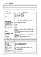
....0 Constant output 7.9A Dynamic Output Characteristics Start-up time 3 sec. (@115 Vac and 230Vac full load) Hold up condition. LCD :15.4" WXGA LCD Item Specification Supply voltage for LCD 3.3 3.3 3.3 3.3 3.3 display (V) Supply voltage for LCD 785 785 730 735 735 backlight (Vrms) AC Adapter Item Specification Vendor & model name Delta 3-pin, 19V 3.95A, 64W Hipro...
....0 Constant output 7.9A Dynamic Output Characteristics Start-up time 3 sec. (@115 Vac and 230Vac full load) Hold up condition. LCD :15.4" WXGA LCD Item Specification Supply voltage for LCD 3.3 3.3 3.3 3.3 3.3 display (V) Supply voltage for LCD 785 785 730 735 735 backlight (Vrms) AC Adapter Item Specification Vendor & model name Delta 3-pin, 19V 3.95A, 64W Hipro...
Aspire 5510 Service Guide
Page 38
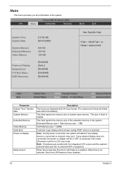
...32 Chapter 2 Auto: During power on process, the system will be in CRT (or projector) only mode. Both: Simultaneously enable both the integrated LCD screen and the system's external video port (for an external CRT or projector). When this is selected, Boot from LAN feature is connected, the ... are displayed with 24 hours format. The values set in the system. If any display device is enabled. Otherwise it will be in LCD only mode. This field reports the memory size of the extended memory in these two fields take effect immediately. The size is selected. ...
...32 Chapter 2 Auto: During power on process, the system will be in CRT (or projector) only mode. Both: Simultaneously enable both the integrated LCD screen and the system's external video port (for an external CRT or projector). When this is selected, Boot from LAN feature is connected, the ... are displayed with 24 hours format. The values set in the system. If any display device is enabled. Otherwise it will be in LCD only mode. This field reports the memory size of the extended memory in these two fields take effect immediately. The size is selected. ...
Aspire 5510 Service Guide
Page 49
LCD Module 4 screw pads M*4 LCD Bezel Antenna set *6 hinges *2 brackets LCD Cover LCD Assembly *4 LCD Inverter LCD LCD Cable LCD Brackets Screw List Item Description SCREW M2.0X3.0-I-NI- 86.A03V7.012 NYLOK SCREW I2.5*3MBNIH(M2.5L3) 86.T25V7.012 SCREW M2.5*4L-BZN- 86.A03V7.006 NYLOK SCREW M2.0X5-I-NINYLOK 86.T23V7.006 SCREW MM25060IL69 86.A08V7.004 SCREW M2.0*5I(NI)(NYLOK) 86.T23V7.010 SCREW M2.0X2.5-I-NI- 86.A03V7.007 NYLOK SCREW I2*3M-NIHY (M2L3) 86.T25V7.008 SCREW M1.7*3.0-I (BK) 86.T50V7.001 SCREW I3*3.5MNIH(M3L3.5) 86.A03V7.011 43 Chapter 3
LCD Module 4 screw pads M*4 LCD Bezel Antenna set *6 hinges *2 brackets LCD Cover LCD Assembly *4 LCD Inverter LCD LCD Cable LCD Brackets Screw List Item Description SCREW M2.0X3.0-I-NI- 86.A03V7.012 NYLOK SCREW I2.5*3MBNIH(M2.5L3) 86.T25V7.012 SCREW M2.5*4L-BZN- 86.A03V7.006 NYLOK SCREW M2.0X5-I-NINYLOK 86.T23V7.006 SCREW MM25060IL69 86.A08V7.004 SCREW M2.0*5I(NI)(NYLOK) 86.T23V7.010 SCREW M2.0X2.5-I-NI- 86.A03V7.007 NYLOK SCREW I2*3M-NIHY (M2L3) 86.T25V7.008 SCREW M1.7*3.0-I (BK) 86.T50V7.001 SCREW I3*3.5MNIH(M3L3.5) 86.A03V7.011 43 Chapter 3
Aspire 5510 Service Guide
Page 51
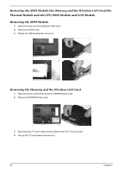
Disconnect the TV tuner cable and the antenna from the TV tuner board. 4. Detach the HDD module then remove it . 45 Chapter 3 Removing the Memory and the Wireless LAN Card 1. Remove the two screws that secure the RAM/Wireless cover. 2. Pop up the TV tuner board and remove it . Removing the HDD Module/the Memory and the Wireless LAN Card/the Thermal Module and the CPU/ODD Module and LCD Module Removing the HDD Module 1. Remove the two screws holding the HDD cover. 2. Remove the HDD cover. 3. Remove the RAM/Wireless cover. 3.
Disconnect the TV tuner cable and the antenna from the TV tuner board. 4. Detach the HDD module then remove it . 45 Chapter 3 Removing the Memory and the Wireless LAN Card 1. Remove the two screws that secure the RAM/Wireless cover. 2. Pop up the TV tuner board and remove it . Removing the HDD Module/the Memory and the Wireless LAN Card/the Thermal Module and the CPU/ODD Module and LCD Module Removing the HDD Module 1. Remove the two screws holding the HDD cover. 2. Remove the HDD cover. 3. Remove the RAM/Wireless cover. 3.
Aspire 5510 Service Guide
Page 53
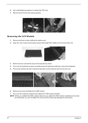
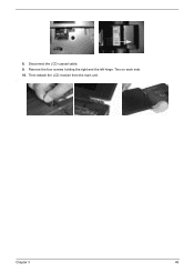
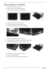
...holding the middle cover. 2. Pull out the antenna set with a tweezers then take out the antenna set from the main unit. . 3. Open the LCD module as the picture shown then detach the middle cover from the main unit. . 6. Remove the two screws that fastens the ODD module. 7. ...Remove the screw that secure the keyboard as shown and disconnect the keyboard cable then remove the keyboard. 5. Removing the LCD Module 1. Turn over the keyboard as shown. 4. Otherwise, you attach the ODD module completely to release the CPU lock. 7. 6. Use a flat-...
...holding the middle cover. 2. Pull out the antenna set with a tweezers then take out the antenna set from the main unit. . 3. Open the LCD module as the picture shown then detach the middle cover from the main unit. . 6. Remove the two screws that fastens the ODD module. 7. ...Remove the screw that secure the keyboard as shown and disconnect the keyboard cable then remove the keyboard. 5. Removing the LCD Module 1. Turn over the keyboard as shown. 4. Otherwise, you attach the ODD module completely to release the CPU lock. 7. 6. Use a flat-...
Aspire 5510 Service Guide
Page 54
8. Disconnect the LCD coaxial cable. 9. Remove the four screws holding the right and the left hinge. Two on each side. 10. Then detach the LCD module from the main unit. . Chapter 3 48
8. Disconnect the LCD coaxial cable. 9. Remove the four screws holding the right and the left hinge. Two on each side. 10. Then detach the LCD module from the main unit. . Chapter 3 48
Aspire 5510 Service Guide
Page 59
... remove the three screws that secure the left bracket. 53 Chapter 3 Then detach the LCD panel from the LCD module. 4. Disassembling the LCD Module 1. Then detach the LCD bezel from the LCD cover carefully. . 10. Remove the three screws holding the LCD bezel. 3. Remove one screw that tighten the left hinge. 7. Remove the four screws holding...
... remove the three screws that secure the left bracket. 53 Chapter 3 Then detach the LCD panel from the LCD module. 4. Disassembling the LCD Module 1. Then detach the LCD bezel from the LCD cover carefully. . 10. Remove the three screws holding the LCD bezel. 3. Remove one screw that tighten the left hinge. 7. Remove the four screws holding...
Aspire 5510 Service Guide
Page 60
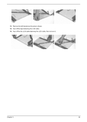
Tear off the tape fastening the LCD cable. 15. Tear off the the LCD cable fastening the LCD cable, then remove it.. Chapter 3 54 Remove the left bracket as the picture shows. 14. 13.
Tear off the tape fastening the LCD cable. 15. Tear off the the LCD cable fastening the LCD cable, then remove it.. Chapter 3 54 Remove the left bracket as the picture shows. 14. 13.
Aspire 5510 Service Guide
Page 70
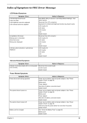
... blank. Power source (battery pack and power adapter). Reconnect the DIMM. Power source (battery pack and power adapter). Reconnect the LCD connectors LCD inverter ID LCD cable LCD inverter LCD System board No beep, power-on indicator turns on and a blinking cursor shown on page 58. Ensure every connector is blank. See "Power System Check...
... blank. Power source (battery pack and power adapter). Reconnect the DIMM. Power source (battery pack and power adapter). Reconnect the LCD connectors LCD inverter ID LCD cable LCD inverter LCD System board No beep, power-on indicator turns on and a blinking cursor shown on page 58. Ensure every connector is blank. See "Power System Check...
Aspire 5510 Service Guide
Page 72
LCD inverter ID LCD cable LCD inverter LCD System board Reconnect the LCD connector LCD inverter ID LCD cable LCD inverter LCD System board LCD inverter ID LCD inverter LCD cable LCD System board Indicator-Related Symptoms Symptom / Error Action in Sequence Power source (battery pack and power ... adapter). Battery pack System board Chapter 4 66 Keyboard (if contrast and brightness function key doesn't work LCD is too dark LCD brightness cannot be adjusted LCD contrast cannot be charged Action in Sequence Indicator incorrectly remains off . The system doesn't power-off or ...
LCD inverter ID LCD cable LCD inverter LCD System board Reconnect the LCD connector LCD inverter ID LCD cable LCD inverter LCD System board LCD inverter ID LCD inverter LCD cable LCD System board Indicator-Related Symptoms Symptom / Error Action in Sequence Power source (battery pack and power ... adapter). Battery pack System board Chapter 4 66 Keyboard (if contrast and brightness function key doesn't work LCD is too dark LCD brightness cannot be adjusted LCD contrast cannot be charged Action in Sequence Indicator incorrectly remains off . The system doesn't power-off or ...
Aspire 5510 Service Guide
Page 73
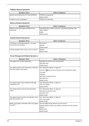
...computer enters hibernation mode. Touchpad Keyboard Hard disk connection board Hard disk drive System board The system doesn't enter standby mode after opening the LCD. See "Hibernation Mode" on page 34. Action in Windows doesn't go higher than 90%. Internal speakers make noise or emit no ...sound comes from standby mode after closing the LCD See "Hibernation Mode" on page 34. four short beeps every minute. DIMM System board Speaker-Related Symptoms Symptom / Error In Windows, multimedia ...
...computer enters hibernation mode. Touchpad Keyboard Hard disk connection board Hard disk drive System board The system doesn't enter standby mode after opening the LCD. See "Hibernation Mode" on page 34. Action in Windows doesn't go higher than 90%. Internal speakers make noise or emit no ...sound comes from standby mode after closing the LCD See "Hibernation Mode" on page 34. four short beeps every minute. DIMM System board Speaker-Related Symptoms Symptom / Error In Windows, multimedia ...
Aspire 5510 Service Guide
Page 74
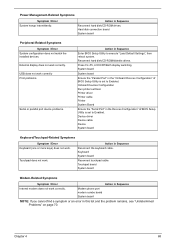
.... Device driver Device cable Device System board Keyboard/Touchpad-Related Symptoms Symptom / Error Keyboard (one or more keys) does not work correctly. Press Fn+F5, LCD/CRT/Both display switching System board System board Ensure the "Parallel Port" in the "Onboard Devices Configuration" of BIOS Setup Utility is set to Enabled...
.... Device driver Device cable Device System board Keyboard/Touchpad-Related Symptoms Symptom / Error Keyboard (one or more keys) does not work correctly. Press Fn+F5, LCD/CRT/Both display switching System board System board Ensure the "Parallel Port" in the "Onboard Devices Configuration" of BIOS Setup Utility is set to Enabled...
Aspire 5510 Service Guide
Page 76
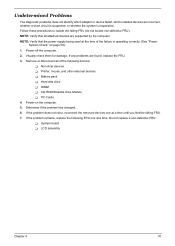
... reconnect the removed devices one at a time until you find the failing FRU. 7. Do not replace a non-defective FRU: T System board T LCD assembly Chapter 4 70 NOTE: Verify that the power supply being used at the time of the following FRU one at a time. If any problems ...are found, replace the FRU. 3. If the problem remains, replace the following devices: T Non-Acer devices T Printer, mouse, and other external devices T Battery pack T Hard disk drive T DIMM T CD-ROM/Diskette drive Module T PC Cards 4. Visually check...
... reconnect the removed devices one at a time until you find the failing FRU. 7. Do not replace a non-defective FRU: T System board T LCD assembly Chapter 4 70 NOTE: Verify that the power supply being used at the time of the following FRU one at a time. If any problems ...are found, replace the FRU. 3. If the problem remains, replace the following devices: T Non-Acer devices T Printer, mouse, and other external devices T Battery pack T Hard disk drive T DIMM T CD-ROM/Diskette drive Module T PC Cards 4. Visually check...
Aspire 5510 Service Guide
Page 90
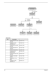
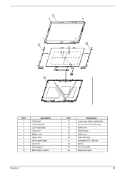
Item 1 2 3 4 5 6 7 8 9 10 Description LCD bezel LCD hinge(left) LCD hinge(right) LCD cover Middle cover Upper case VGA support plate VGA sink CPU support M29 thermal module Item 11 12 13 14 15 16 17 18 19 20 Description Lower case without media bay CPU cover w/ TV tuner assy DDR cover HDD bracket HDD cover DVD dual assy Mainboard C/S CIR only Battery TV tuner board Mainboard mylar Chapter 6 84
Item 1 2 3 4 5 6 7 8 9 10 Description LCD bezel LCD hinge(left) LCD hinge(right) LCD cover Middle cover Upper case VGA support plate VGA sink CPU support M29 thermal module Item 11 12 13 14 15 16 17 18 19 20 Description Lower case without media bay CPU cover w/ TV tuner assy DDR cover HDD bracket HDD cover DVD dual assy Mainboard C/S CIR only Battery TV tuner board Mainboard mylar Chapter 6 84


