Aspire 4720, 4720Z User's Guide EN
Page 5
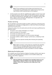
... cord set . Unplug this product. • Use the product only with your product. Replacing the battery pack The notebook uses lithium batteries. Warning! Do not disassemble or dispose of fire or explosion. Refer all servicing to dangerous voltage points or other controls may result in damage and will often require extensive...
... cord set . Unplug this product. • Use the product only with your product. Replacing the battery pack The notebook uses lithium batteries. Warning! Do not disassemble or dispose of fire or explosion. Refer all servicing to dangerous voltage points or other controls may result in damage and will often require extensive...

Aspire 4720, 4720Z User's Guide EN
Page 104
.... This product incorporates copyright protection technology that is protected by Macrovision. Use of this computer is a laser product. AVOID EXPOSURE TO BEAM. Reverse engineering or disassembly is produced with this copyright protection technology must be authorized by Macrovision, and is intended for home and other intellectual property rights. English 86 Laser...
.... This product incorporates copyright protection technology that is protected by Macrovision. Use of this computer is a laser product. AVOID EXPOSURE TO BEAM. Reverse engineering or disassembly is produced with this copyright protection technology must be authorized by Macrovision, and is intended for home and other intellectual property rights. English 86 Laser...

Aspire 4720, G, Z, 4320 Service Guide
Page 57
To disassemble the computer, you remove the stripe cover, please be careful not to avoid mismatch when putting back the components. Chapter 3 51 When you need the ... flat head screw driver T Tweezers NOTE: The screws for maintenance and troubleshooting. During the disassembly process, group the screws with the corresponding components to scrape the cover. Chapter 3 Machine Disassembly and Replacement This chapter contains step-by-step procedures on how to disassemble the notebook computer for the different components vary in size.
To disassemble the computer, you remove the stripe cover, please be careful not to avoid mismatch when putting back the components. Chapter 3 51 When you need the ... flat head screw driver T Tweezers NOTE: The screws for maintenance and troubleshooting. During the disassembly process, group the screws with the corresponding components to scrape the cover. Chapter 3 Machine Disassembly and Replacement This chapter contains step-by-step procedures on how to disassemble the notebook computer for the different components vary in size.

Aspire 4720, G, Z, 4320 Service Guide
Page 58
Remove the battery pack. 52 Chapter 3 Unplug the AC adapter and all peripherals. 2. General Information Before You Begin Before proceeding with the disassembly procedure, make sure that you do the following: 1. Turn off the power to the system and all power and signal cables from the system. 3.
Remove the battery pack. 52 Chapter 3 Unplug the AC adapter and all peripherals. 2. General Information Before You Begin Before proceeding with the disassembly procedure, make sure that you do the following: 1. Turn off the power to the system and all power and signal cables from the system. 3.

Aspire 4720, G, Z, 4320 Service Guide
Page 59
... want to remove the system board, you on the components that order. Disassembly Procedure Flowchart The flowchart on the succeeding page gives you a graphic representation on the entire disassembly sequence and instructs you must first remove the keyboard, then disassemble the inside assembly frame in that need to lower case assembly on upper...
... want to remove the system board, you on the components that order. Disassembly Procedure Flowchart The flowchart on the succeeding page gives you a graphic representation on the entire disassembly sequence and instructs you must first remove the keyboard, then disassemble the inside assembly frame in that need to lower case assembly on upper...

Aspire 4720, G, Z, 4320 Service Guide
Page 66
... and remove the three screws fastening the switch board. 3. Remove the switch board from the lower case assembly. Disassembling the Lower Case Assembly Removing the Main Board 1. Remove the main board. 60 Chapter 3 Disassembling the Main Unit Separate the Main Unit Into the Upper and the Lower Case Assembly 1. Disconnect both ends...
... and remove the three screws fastening the switch board. 3. Remove the switch board from the lower case assembly. Disassembling the Lower Case Assembly Removing the Main Board 1. Remove the main board. 60 Chapter 3 Disassembling the Main Unit Separate the Main Unit Into the Upper and the Lower Case Assembly 1. Disconnect both ends...

Aspire 4720, G, Z, 4320 Service Guide
Page 67
Removing the Audio Board 4. Remove the screw fastening the audio board. 5. Remove the two screws fastening the Bluetooth module. 2. Remove the three screws fastening the speakers. 4. Remove the audio board. Disconnect the Bluetooth cable to remove the Bluetooth module. Remove the speakers. Disassembling the Upper Case Assembly Removing the Bluetooth Module 1. Chapter 3 61 Removing the Speakers 3.
Removing the Audio Board 4. Remove the screw fastening the audio board. 5. Remove the two screws fastening the Bluetooth module. 2. Remove the three screws fastening the speakers. 4. Remove the audio board. Disconnect the Bluetooth cable to remove the Bluetooth module. Remove the speakers. Disassembling the Upper Case Assembly Removing the Bluetooth Module 1. Chapter 3 61 Removing the Speakers 3.
Aspire 4720, G, Z, 4320 Service Guide
Page 68
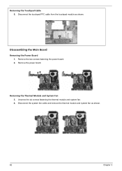
Removing the Thermal Module and System Fan 3. Remove the two screws fastening the power board. 2. Disconnect the system fan cable and remove the thermal module and system fan as shown. Unscrew the six screws fastening the thermal module and system fan. 4. Disconnect the touchpad FFC cable from the touchpad module as shown. 62 Chapter 3 Disassembling the Main Board Removing the Power Board 1. Remove the power board. Removing the Touchpad Cable 5.
Removing the Thermal Module and System Fan 3. Remove the two screws fastening the power board. 2. Disconnect the system fan cable and remove the thermal module and system fan as shown. Unscrew the six screws fastening the thermal module and system fan. 4. Disconnect the touchpad FFC cable from the touchpad module as shown. 62 Chapter 3 Disassembling the Main Board Removing the Power Board 1. Remove the power board. Removing the Touchpad Cable 5.

Aspire 4720, G, Z, 4320 Service Guide
Page 70
Remove the four screws holding the LCD. 5. Detach the two inverter cable connectors from the LCD module carefully. 4. Remove the two screws fastening the left LCD bracket and detach it . 64 Chapter 3 Detach the LCD bezel from the inverter board. 6. Remove the two screws fastening the right LCD bracket and detach it . 9. Then remove the six screws fastening the LCD bezel. 3. Disconnect the CCD cable connector from the LCD cover. 8. Disassembling the LCD Module 1. Remove the six screw rubbers as shown. 2. Take out the LCD from the CCD module. 7.
Remove the four screws holding the LCD. 5. Detach the two inverter cable connectors from the LCD module carefully. 4. Remove the two screws fastening the left LCD bracket and detach it . 64 Chapter 3 Detach the LCD bezel from the inverter board. 6. Remove the two screws fastening the right LCD bracket and detach it . 9. Then remove the six screws fastening the LCD bezel. 3. Disconnect the CCD cable connector from the LCD cover. 8. Disassembling the LCD Module 1. Remove the six screw rubbers as shown. 2. Take out the LCD from the CCD module. 7.

Aspire 4720, G, Z, 4320 Service Guide
Page 71
Disassembling the ODD Module 1. Remove the two screws holding the optical bracket. 2. Chapter 3 65 Remove the two screws fastening the bracket to the HDD module. 2. Remove the CCD module from the optical disk drive. Then remove the optical bracket from the LCD cover as shown. Remove the bracket. 10. Disconnect the LCD cable from the LCD cover and remove the microphone. 12. Disassembling the External Modules Disassembling the HDD Module 1. Detach the microphone cable from the rear of the LCD. 11.
Disassembling the ODD Module 1. Remove the two screws holding the optical bracket. 2. Chapter 3 65 Remove the two screws fastening the bracket to the HDD module. 2. Remove the CCD module from the optical disk drive. Then remove the optical bracket from the LCD cover as shown. Remove the bracket. 10. Disconnect the LCD cable from the LCD cover and remove the microphone. 12. Disassembling the External Modules Disassembling the HDD Module 1. Detach the microphone cable from the rear of the LCD. 11.


