
Aspire 4220 / 4520 User's Guide EN
Page 5
... following requirements: detachable type, UL listed/CSA certified, type SPT-2, rated 7 A 125 V minimum, VDE approved or its equivalent, 4.6 meters (15 feet) maximum length. Do not disassemble or dispose of them away from unexpected noise produced by the operating instructions, since improper adjustment of other controls may interfere with the performance of...
... following requirements: detachable type, UL listed/CSA certified, type SPT-2, rated 7 A 125 V minimum, VDE approved or its equivalent, 4.6 meters (15 feet) maximum length. Do not disassemble or dispose of them away from unexpected noise produced by the operating instructions, since improper adjustment of other controls may interfere with the performance of...

Aspire 4220 / 4520 User's Guide EN
Page 105
... (shown below) is located on the recorded image and does not constitute a malfunction. AVOID EXPOSURE TO BEAM. EVITE EXPONERSE A LOS RAYOS. VARO! Reverse engineering or disassembly is a laser product. APPAREIL A LASER DE CLASSE 1 PRODUIT LASERATTENTION: RADIATION DU FAISCEAU LASER INVISIBLE EN CAS D'OUVERTURE. LUOKAN 1 LASERLAITE LASER KLASSE 1 VORSICHT: UNSICHTBARE LASERSTRAHLUNG, WENN...
... (shown below) is located on the recorded image and does not constitute a malfunction. AVOID EXPOSURE TO BEAM. EVITE EXPONERSE A LOS RAYOS. VARO! Reverse engineering or disassembly is a laser product. APPAREIL A LASER DE CLASSE 1 PRODUIT LASERATTENTION: RADIATION DU FAISCEAU LASER INVISIBLE EN CAS D'OUVERTURE. LUOKAN 1 LASERLAITE LASER KLASSE 1 VORSICHT: UNSICHTBARE LASERSTRAHLUNG, WENN...

Service Guide
Page 59
To disassemble the computer, you remove the stripe cover, please be careful not to scrape the cover. When you need the following tools: T Wrist grounding strap and ... screw driver T Tweezers NOTE: The screws for maintenance and troubleshooting. Chapter 3 53 During the disassembly process, group the screws with the corresponding components to disassemble the notebook computer for the different components vary in size. Chapter 3 Machine Disassembly and Replacement This chapter contains step-by-step procedures on how to avoid mismatch when...
To disassemble the computer, you remove the stripe cover, please be careful not to scrape the cover. When you need the following tools: T Wrist grounding strap and ... screw driver T Tweezers NOTE: The screws for maintenance and troubleshooting. Chapter 3 53 During the disassembly process, group the screws with the corresponding components to disassemble the notebook computer for the different components vary in size. Chapter 3 Machine Disassembly and Replacement This chapter contains step-by-step procedures on how to avoid mismatch when...

Service Guide
Page 60
Remove the battery pack. 54 Chapter 3 Unplug the AC adapter and all peripherals. 2. General Information Before You Begin Before proceeding with the disassembly procedure, make sure that you do the following: 1. Turn off the power to the system and all power and signal cables from the system. 3.
Remove the battery pack. 54 Chapter 3 Unplug the AC adapter and all peripherals. 2. General Information Before You Begin Before proceeding with the disassembly procedure, make sure that you do the following: 1. Turn off the power to the system and all power and signal cables from the system. 3.

Service Guide
Page 61
... assembly on bottom side C*2 upper case assembly to be removed during servicing. Disassembly Procedure Flowchart The flowchart on the succeeding page gives you a graphic representation on the entire disassembly sequence and instructs you must first remove the keyboard, then disassemble the inside assembly frame in that need to lower case assembly on the...
... assembly on bottom side C*2 upper case assembly to be removed during servicing. Disassembly Procedure Flowchart The flowchart on the succeeding page gives you a graphic representation on the entire disassembly sequence and instructs you must first remove the keyboard, then disassemble the inside assembly frame in that need to lower case assembly on the...

Service Guide
Page 69
... Assembly Removing the Main Board 1. Chapter 3 63 Gently lift off the upper case assembly from the main unit. 4. Disconnect the touchpad, speaker and bluetooth cables. 6. Disassembling the Main Unit Separate the Main Unit Into the Upper and the Lower Case Assembly 1. Turn the notebook over and remove the three screws fastening...
... Assembly Removing the Main Board 1. Chapter 3 63 Gently lift off the upper case assembly from the main unit. 4. Disconnect the touchpad, speaker and bluetooth cables. 6. Disassembling the Main Unit Separate the Main Unit Into the Upper and the Lower Case Assembly 1. Turn the notebook over and remove the three screws fastening...

Service Guide
Page 70
Removing the Speakers 3. Remove the three screws fastening the speakers. 5. Remove the screw fastening the audio board. 5. Remove the two screws fastening the bluetooth module. 2. Remove the speaker cable from the upper case. 4. Disassembling the Upper Case Assembly Removing the Bluetooth Module 1. Remove the speakers. 64 Chapter 3 Removing the Audio Board 4. Remove the audio board. Remove the bluetooth module.
Removing the Speakers 3. Remove the three screws fastening the speakers. 5. Remove the screw fastening the audio board. 5. Remove the two screws fastening the bluetooth module. 2. Remove the speaker cable from the upper case. 4. Disassembling the Upper Case Assembly Removing the Bluetooth Module 1. Remove the speakers. 64 Chapter 3 Removing the Audio Board 4. Remove the audio board. Remove the bluetooth module.

Service Guide
Page 71
Remove the screw fastening the MDC card module. 4. Remove the two screws fastening the USB board. 2. Remove the MDC card module. Disassembling the Main Board Removing the USB Board 1. Removing the MDC Card Module 3. Disconnect the touchpad cable from the touchpad module as shown. Removing the Touchpad Cable 6. Remove the USB board. Chapter 3 65
Remove the screw fastening the MDC card module. 4. Remove the two screws fastening the USB board. 2. Remove the MDC card module. Disassembling the Main Board Removing the USB Board 1. Removing the MDC Card Module 3. Disconnect the touchpad cable from the touchpad module as shown. Removing the Touchpad Cable 6. Remove the USB board. Chapter 3 65
Service Guide
Page 73
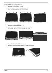
Remove the four screws holding the LCD. 5. Take out the LCD from the LCD module carefully. 4. Chapter 3 67 Detach the LCD bezel from the LCD panel. 8. Disconnect the CCD cable connector from the inverter board. 6. Then remove the six screws fastening the LCD bezel. 3. Detach the two inverter cable connectors from the CCD board. 7. Remove the six screw rubbers as shown. 2. Remove the two screws fastening the left LCD bracket and detach it. Disassembling the LCD Module 1.
Remove the four screws holding the LCD. 5. Take out the LCD from the LCD module carefully. 4. Chapter 3 67 Detach the LCD bezel from the LCD panel. 8. Disconnect the CCD cable connector from the inverter board. 6. Then remove the six screws fastening the LCD bezel. 3. Detach the two inverter cable connectors from the CCD board. 7. Remove the six screw rubbers as shown. 2. Remove the two screws fastening the left LCD bracket and detach it. Disassembling the LCD Module 1.

Service Guide
Page 74
Remove the bracket. Disassembling the External Modules Disassembling the HDD Module 1. Remove the two screws holding the optical bracket. 2. Then remove the optical bracket from the LCD cover as shown. Remove the two screws fastening the right LCD bracket and detach it. 10. 9. Remove the CCD from the optical disk drive. 68 Chapter 3 Remove the two screws fastening the bracket to the HDD module. 2. Disassembling the ODD Module 1. Detach the microphone cable from the LCD. 11. Disconnect the LCD cable from the LCD cover and remove the microphone. 12.
Remove the bracket. Disassembling the External Modules Disassembling the HDD Module 1. Remove the two screws holding the optical bracket. 2. Then remove the optical bracket from the LCD cover as shown. Remove the two screws fastening the right LCD bracket and detach it. 10. 9. Remove the CCD from the optical disk drive. 68 Chapter 3 Remove the two screws fastening the bracket to the HDD module. 2. Disassembling the ODD Module 1. Detach the microphone cable from the LCD. 11. Disconnect the LCD cable from the LCD cover and remove the microphone. 12.


