Aspire 4220 / 4520 User's Guide EN
Page 12
... for making an Acer notebook your mobile computing needs. If Adobe Reader is available in Portable Document Format (PDF) and comes preloaded on how to thank you get started with setting up your new computer. Follow the instructions on the screen to access it contains warranty information and the general regulations and safety notices for Starters... Follow these steps to complete the installation. Your guides...
... for making an Acer notebook your mobile computing needs. If Adobe Reader is available in Portable Document Format (PDF) and comes preloaded on how to thank you get started with setting up your new computer. Follow the instructions on the screen to access it contains warranty information and the general regulations and safety notices for Starters... Follow these steps to complete the installation. Your guides...

Aspire 4220 / 4520 User's Guide EN
Page 17
... Traveling internationally with the computer 67 Preparing the computer 67 What to bring with you 67 Special considerations 67 Securing your computer 68 Using a computer security lock 68 Using passwords 68 Entering passwords 69 Setting passwords 69 Expanding through options 70 Connectivity options 70 Fax/data modem 70 Built-in network feature 71 Universal Serial Bus (USB) 71 IEEE 1394 port 72 ExpressCard 73 Installing memory 74 BIOS utility 75
... Traveling internationally with the computer 67 Preparing the computer 67 What to bring with you 67 Special considerations 67 Securing your computer 68 Using a computer security lock 68 Using passwords 68 Entering passwords 69 Setting passwords 69 Expanding through options 70 Connectivity options 70 Fax/data modem 70 Built-in network feature 71 Universal Serial Bus (USB) 71 IEEE 1394 port 72 ExpressCard 73 Installing memory 74 BIOS utility 75

Aspire 4220 / 4520 User's Guide EN
Page 22
View and adjust settings for On Battery and Plugged In modes by clicking "More Power Options". You can also turn on . 4 If necessary, change the display and sleep settings you to save and quickly switch to a personalized set of power options. 1 Click the Create Power Plan icon. 2 Enter a name for configuring your power management options. Note: You cannot delete the predefined power plans. To switch between , edit, delete and restore power plans, as required. Using power plans Acer ePower Management comes with...
View and adjust settings for On Battery and Plugged In modes by clicking "More Power Options". You can also turn on . 4 If necessary, change the display and sleep settings you to save and quickly switch to a personalized set of power options. 1 Click the Create Power Plan icon. 2 Enter a name for configuring your power management options. Note: You cannot delete the predefined power plans. To switch between , edit, delete and restore power plans, as required. Using power plans Acer ePower Management comes with...

Aspire 4220 / 4520 User's Guide EN
Page 38
indicator 3 Optical drive eject Ejects the optical disk from the drive. Rear view # Icon Item 1 Ventilation slots Description Enable the computer to a Kensington-compatible computer security lock. button 4 Emergency eject Ejects the optical drive tray when the hole computer is active. accepts CDs or DVDs (slot-load or tray-load depending on model). 2 Optical disk access Lights up when the optical drive is turned off. 5 2 USB 2.0 port Connect to USB 2.0 devices (e.g., USB mouse, USB camera). 6 DC-in jack Connects to...
indicator 3 Optical drive eject Ejects the optical disk from the drive. Rear view # Icon Item 1 Ventilation slots Description Enable the computer to a Kensington-compatible computer security lock. button 4 Emergency eject Ejects the optical drive tray when the hole computer is active. accepts CDs or DVDs (slot-load or tray-load depending on model). 2 Optical disk access Lights up when the optical drive is turned off. 5 2 USB 2.0 port Connect to USB 2.0 devices (e.g., USB mouse, USB camera). 6 DC-in jack Connects to...

Aspire 4220 / 4520 User's Guide EN
Page 59
... volume control icon on the screen. If pressing a key does not turn the display back on. Press the display toggle hotkey + to toggle the display back to the computer. • If the Sleep indicator is lit, the computer is in the external USB floppy drive? In Windows, look at the volume control (speaker) icon on the power, but the computer does not start or boot up. Press and release the power button...
... volume control icon on the screen. If pressing a key does not turn the display back on. Press the display toggle hotkey + to toggle the display back to the computer. • If the Sleep indicator is lit, the computer is in the external USB floppy drive? In Windows, look at the volume control (speaker) icon on the power, but the computer does not start or boot up. Press and release the power button...

Aspire 4220 / 4520 User's Guide EN
Page 76
... and replace your cable provider is located. Using TeleText functions For regions with the TeleText service, TeleText can be activated by channel number or category. The Region option allows you to set the quality of video recorded from the TV. English 57 Find program Clicking the Find Program button allows you to search for programs by using the onscreen controller or the remote control. press...
... and replace your cable provider is located. Using TeleText functions For regions with the TeleText service, TeleText can be activated by channel number or category. The Region option allows you to set the quality of video recorded from the TV. English 57 Find program Clicking the Find Program button allows you to search for programs by using the onscreen controller or the remote control. press...

Aspire 4220 / 4520 User's Guide EN
Page 98
... instructions on screen to complete the process. English 79 Burn backup disc Using the Burn Disc page of Acer eRecovery Management, you can burn the factory default image, a user backup image, the current system configuration, or an application backup image to CD or DVD. 1 Press + or select Acer eRecovery Management from the Empowering Technology toolbar to start Acer eRecovery Management. 2 Switch to the restore and recovery page by selecting the Burn Disc button. 3 Select the type...
... instructions on screen to complete the process. English 79 Burn backup disc Using the Burn Disc page of Acer eRecovery Management, you can burn the factory default image, a user backup image, the current system configuration, or an application backup image to CD or DVD. 1 Press + or select Acer eRecovery Management from the Empowering Technology toolbar to start Acer eRecovery Management. 2 Switch to the restore and recovery page by selecting the Burn Disc button. 3 Select the type...

Service Guide
Page 24
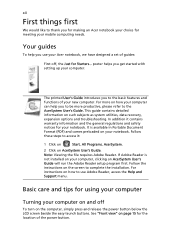
... dollar sign at the upper-center of the keyboard. NOTE: Some fonts and software do not support the Euro symbol. Please refer to return. Press any key to www.microsoft.com/ typography/faq/faq12.htm for more information. Open a text editor or word processor. 2. Hot Key + + + Icon Function Display toggle Screen blank Touchpad toggle Description Switches display output between the display screen, external monitor (if connected) and both.
... dollar sign at the upper-center of the keyboard. NOTE: Some fonts and software do not support the Euro symbol. Please refer to return. Press any key to www.microsoft.com/ typography/faq/faq12.htm for more information. Open a text editor or word processor. 2. Hot Key + + + Icon Function Display toggle Screen blank Touchpad toggle Description Switches display output between the display screen, external monitor (if connected) and both.
Service Guide
Page 38
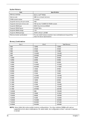
... table lists some system memory configurations. System Memory Item Memory controller Memory size DIMM socket number Supports memory size per socket Supports maximum memory size Supports DIMM type Supports DIMM Speed Supports DIMM voltage Supports DIMM package Memory module combinations Specification Built-in Intel® PM965 0MB (no on-board memory) 2 sockets 2GB 4GB (by two 1024MB SO-DIMM module) DDR 2 Synchronous DRAM 533/667 MHz 1.8V JEDEC 200-pin soDIMM You can install memory modules...
... table lists some system memory configurations. System Memory Item Memory controller Memory size DIMM socket number Supports memory size per socket Supports maximum memory size Supports DIMM type Supports DIMM Speed Supports DIMM voltage Supports DIMM package Memory module combinations Specification Built-in Intel® PM965 0MB (no on-board memory) 2 sockets 2GB 4GB (by two 1024MB SO-DIMM module) DDR 2 Synchronous DRAM 533/667 MHz 1.8V JEDEC 200-pin soDIMM You can install memory modules...
Service Guide
Page 50
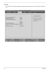
PhoenixBIOS Setup Utility Information Main Security Boot Power Exit Supervisor Password Is : User Password Is : SATA Port 0 Disk status Clear Clear Clear Set Supervisor Password [Enter] Set User Password [Enter] Set SATA Port 0 HDD Password [Enter] Password on boot : [Enabled] Item Specific Help Supervisor Password controls access to the setup utility. F1 Help Esc Exit Select Item Select Menu F5/F6 Change Values Enter Select Sub-Menu F9 Setup Defaults F10 Save and Exit 44 Chapter 2 Security The Security screen contains parameters that help safeguard and protect your ...
PhoenixBIOS Setup Utility Information Main Security Boot Power Exit Supervisor Password Is : User Password Is : SATA Port 0 Disk status Clear Clear Clear Set Supervisor Password [Enter] Set User Password [Enter] Set SATA Port 0 HDD Password [Enter] Password on boot : [Enabled] Item Specific Help Supervisor Password controls access to the setup utility. F1 Help Esc Exit Select Item Select Menu F5/F6 Change Values Enter Select Sub-Menu F9 Setup Defaults F10 Save and Exit 44 Chapter 2 Security The Security screen contains parameters that help safeguard and protect your ...
Service Guide
Page 51
...When user password is Hard Disk Password Status Set Supervisor Password Set User Password Set Hard Disk Password Password on the screen. 3. The user can not either enter the Setup menu nor change the value of parameters. Parameter Supervisor Password is User Password is set , this password protects the BIOS Setup Utility from unauthorized access. The user can not either enter the Setup menu nor change the value of parameters. The user can not exceed 8 alphanumeric characters (A-Z, a-z, 0-9, not case sensitive). Option Clear or Set Clear or Set Clear or Set Disabled or Enabled...
...When user password is Hard Disk Password Status Set Supervisor Password Set User Password Set Hard Disk Password Password on the screen. 3. The user can not either enter the Setup menu nor change the value of parameters. Parameter Supervisor Password is User Password is set , this password protects the BIOS Setup Utility from unauthorized access. The user can not either enter the Setup menu nor change the value of parameters. The user can not exceed 8 alphanumeric characters (A-Z, a-z, 0-9, not case sensitive). Option Clear or Set Clear or Set Clear or Set Disabled or Enabled...

Service Guide
Page 52
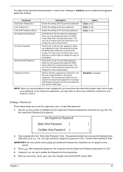
... e key. The password setting is OK, the screen will show you have changed the settings, press u to save the changes and exit the BIOS Setup Utility. Retype the password in the Confirm New Password field. 4. If the verification is complete after the user presses u. When you the Setup Warning. 46 Chapter 2 If the current password entered does not match the actual current password, the screen will display as following. Removing a Password Follow...
... e key. The password setting is OK, the screen will show you have changed the settings, press u to save the changes and exit the BIOS Setup Utility. Retype the password in the Confirm New Password field. 4. If the verification is complete after the user presses u. When you the Setup Warning. 46 Chapter 2 If the current password entered does not match the actual current password, the screen will display as following. Removing a Password Follow...
Service Guide
Page 81
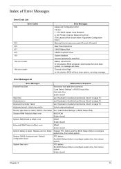
... Clock Error CMOS Battery Bad CMOS Checksum Error System disabled. Battery critical LOW In this situation BIOS will be shown before "Equipment Configuration Error") Memory Error at offset: nnnn DIMM System board System battery is specified. Error Message List Error Messages FRU/Action in BIOS Setup Utility. Default configuration used RTC battery Run BIOS Setup Utility to reconfigure system time, then reboot system. Hard disk drive System board Stuck Key see "Keyboard or Auxiliary Input Device Check" on page 70. Index of Error Messages Error Code List Error Codes...
... Clock Error CMOS Battery Bad CMOS Checksum Error System disabled. Battery critical LOW In this situation BIOS will be shown before "Equipment Configuration Error") Memory Error at offset: nnnn DIMM System board System battery is specified. Error Message List Error Messages FRU/Action in BIOS Setup Utility. Default configuration used RTC battery Run BIOS Setup Utility to reconfigure system time, then reboot system. Hard disk drive System board Stuck Key see "Keyboard or Auxiliary Input Device Check" on page 70. Index of Error Messages Error Code List Error Codes...

Service Guide
Page 82
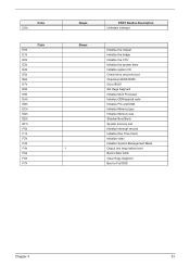
... fixed disk and drive A: are properly identified. Error Message List Error Messages Real time clock error Previous boot incomplete - Cache disabled CPU ID: DMA Test Failed Software NMI Failed Fail-Safe Timer NMI Failed Device Address Conflict Allocation Error for device Failing Bits: nnnn Fixed Disk n Invalid System Configuration Data I/O device IRQ conflict Operating system not found by POST differed from CMOS Diskette drive A error Incorrect Drive A type - Default configuration used Memory size found FRU/Action in BIOS Setup Utility See "External Diskette Drive...
... fixed disk and drive A: are properly identified. Error Message List Error Messages Real time clock error Previous boot incomplete - Cache disabled CPU ID: DMA Test Failed Software NMI Failed Fail-Safe Timer NMI Failed Device Address Conflict Allocation Error for device Failing Bits: nnnn Fixed Disk n Invalid System Configuration Data I/O device IRQ conflict Operating system not found by POST differed from CMOS Diskette drive A error Incorrect Drive A type - Default configuration used Memory size found FRU/Action in BIOS Setup Utility See "External Diskette Drive...

Service Guide
Page 85
... devices Initialize all video adapters in system QuietBoot start (optional) Shadow video BIOS ROM Display BIOS copyright notice Display CPU type and speed Initialize EISA board Test keyboard Set key click if enabled Test for unexpected interrupts Initialize POST display service Display prompt "Press F2 to enter SETUP" Disable CPU cache Test RAM between 512 and 640 KB Test extended memory Test extended memory address lines Jump to User Patch1 Configure advanced cache registers Initialize Multi Processor APIC Enable external and CPU caches Setup...
... devices Initialize all video adapters in system QuietBoot start (optional) Shadow video BIOS ROM Display BIOS copyright notice Display CPU type and speed Initialize EISA board Test keyboard Set key click if enabled Test for unexpected interrupts Initialize POST display service Display prompt "Press F2 to enter SETUP" Disable CPU cache Test RAM between 512 and 640 KB Test extended memory Test extended memory address lines Jump to User Patch1 Configure advanced cache registers Initialize Multi Processor APIC Enable external and CPU caches Setup...

Service Guide
Page 86
... for SMART drive (optional) Shadow option ROMs Set up Power Management Initialize security engine (optional) Enable hardware interrupts Determine number of ATA and SCSI drives Set time of ATA drives (optional) Initialize hard-disk controllers Initialize local-bus hard-disk controllers Jump to boot with INT 19 Initialize POST Error Manager (PEM) Initialize error logging Initialize error display function Initialize system error handler PnPnd dual CMOS (optional) Initialize notebook docking (optional) Initialize notebook docking late Force check (optional) Extended checksum (optional) Chapter...
... for SMART drive (optional) Shadow option ROMs Set up Power Management Initialize security engine (optional) Enable hardware interrupts Determine number of ATA and SCSI drives Set time of ATA drives (optional) Initialize hard-disk controllers Initialize local-bus hard-disk controllers Jump to boot with INT 19 Initialize POST Error Manager (PEM) Initialize error logging Initialize error display function Initialize system error handler PnPnd dual CMOS (optional) Initialize notebook docking (optional) Initialize notebook docking late Force check (optional) Extended checksum (optional) Chapter...
Service Guide
Page 87
... the CPU Initialize the system timer Initialize system I/O Check force recovery boot Checksum BIOS ROM Go to BIOS Set Huge Segment Initialize Multi Processor Initialize OEM special code Initialize PIC and DMA Initialize Memory type Initialize Memory size Shadow Boot Block System memory test Initialize interrupt vectors Initialize Run Time Clock Initialize video Initialize System Management Mode Output one beep before boot Boot to Mini DOS Clear Huge Segment Boot...
... the CPU Initialize the system timer Initialize system I/O Check force recovery boot Checksum BIOS ROM Go to BIOS Set Huge Segment Initialize Multi Processor Initialize OEM special code Initialize PIC and DMA Initialize Memory type Initialize Memory size Shadow Boot Block System memory test Initialize interrupt vectors Initialize Run Time Clock Initialize video Initialize System Management Mode Output one beep before boot Boot to Mini DOS Clear Huge Segment Boot...

Service Guide
Page 88
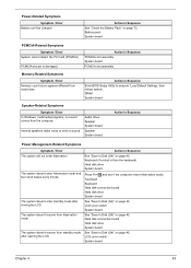
... the LCD connectors. Action in Sequence Enter BIOS Utility to -FRU Error Message LCD-Related Symptoms Symptom / Error LCD backlight doesn't work ). Keyboard (if contrast and brightness function key doesn't work LCD is too dark LCD brightness cannot be adjusted LCD contrast cannot be adjusted Unreadable LCD screen Missing pels in Sequence Indicator incorrectly remains off . LCD inverter ID LCD cable LCD inverter LCD System board Reconnect the LCD connector LCD inverter ID LCD cable LCD inverter LCD System board LCD inverter ID LCD inverter LCD cable LCD System board Indicator-Related...
... the LCD connectors. Action in Sequence Enter BIOS Utility to -FRU Error Message LCD-Related Symptoms Symptom / Error LCD backlight doesn't work ). Keyboard (if contrast and brightness function key doesn't work LCD is too dark LCD brightness cannot be adjusted LCD contrast cannot be adjusted Unreadable LCD screen Missing pels in Sequence Indicator incorrectly remains off . LCD inverter ID LCD cable LCD inverter LCD System board Reconnect the LCD connector LCD inverter ID LCD cable LCD inverter LCD System board LCD inverter ID LCD inverter LCD cable LCD System board Indicator-Related...
Service Guide
Page 89
... actual size. Hard disk connection board Hard disk drive System board See "Save to Disk (S4)" on page 45. Audio driver Speaker System board Speaker System board Action in Sequence Enter BIOS Setup Utility to execute "Load Default Settings, then reboot system. DIMM System board Speaker-Related Symptoms Symptom / Error In Windows, multimedia programs, no sound. Touchpad Keyboard Hard disk connection board Hard disk drive System board See "Save to Disk (S4)" on page 45. Keyboard (if control is damaged. Power-Related Symptoms Symptom / Error Battery can't be charged Action in...
... actual size. Hard disk connection board Hard disk drive System board See "Save to Disk (S4)" on page 45. Audio driver Speaker System board Speaker System board Action in Sequence Enter BIOS Setup Utility to execute "Load Default Settings, then reboot system. DIMM System board Speaker-Related Symptoms Symptom / Error In Windows, multimedia programs, no sound. Touchpad Keyboard Hard disk connection board Hard disk drive System board See "Save to Disk (S4)" on page 45. Keyboard (if control is damaged. Power-Related Symptoms Symptom / Error Battery can't be charged Action in...

Service Guide
Page 91
..., replace the FRU. Rerun the test to do the following: 1. Chapter 4 85 Run the advanced diagnostic test for the system board in loop mode at least 10 times. 2. Intermittent Problems Intermittent system hang problems can be considered only when a recurring problem exists. When analyzing an intermittent problem, do with a hardware defect, such as: cosmic radiation, electrostatic discharge, or software errors.
..., replace the FRU. Rerun the test to do the following: 1. Chapter 4 85 Run the advanced diagnostic test for the system board in loop mode at least 10 times. 2. Intermittent Problems Intermittent system hang problems can be considered only when a recurring problem exists. When analyzing an intermittent problem, do with a hardware defect, such as: cosmic radiation, electrostatic discharge, or software errors.


