
Acer Aspire 1410 and Aspire 1680 Service Guide
Page 8
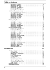
... 1 System Block Diagram 3 Board Layout 4 Top View 4 Bottom View 5 An Aspire Tour 7 Front View 7 Closed Front View 8 Left View 9 Right View 10 Rear Panel 11 Bottom Panel 12 Indicators 13 Using the Keyboard 15 Lock Keys 15 Embedded Numeric Keypad 16 Windows Keys 17 Hot Keys 18 Special...Flash Utility 49 Chapter 3 Machine Disassembly and Replacement 50 General Information 51 Before You Begin 51 Disassembly Procedure Flowchart 53 Removing the Battery Pack 55 Removing the HDD Module/the Memory and the Wireless LAN Card/the Thermal Module and the CPU/ODD Module and LCD ...
... 1 System Block Diagram 3 Board Layout 4 Top View 4 Bottom View 5 An Aspire Tour 7 Front View 7 Closed Front View 8 Left View 9 Right View 10 Rear Panel 11 Bottom Panel 12 Indicators 13 Using the Keyboard 15 Lock Keys 15 Embedded Numeric Keypad 16 Windows Keys 17 Hot Keys 18 Special...Flash Utility 49 Chapter 3 Machine Disassembly and Replacement 50 General Information 51 Before You Begin 51 Disassembly Procedure Flowchart 53 Removing the Battery Pack 55 Removing the HDD Module/the Memory and the Wireless LAN Card/the Thermal Module and the CPU/ODD Module and LCD ...

Acer Aspire 1410 and Aspire 1680 Service Guide
Page 63
...Wireless LAN Card Memory CPU *2 IO Bezel *2 Heatsink Cover *2 Thermal Module ODD Module *6 ODD Connector Board ODD Holder ODD Drive *3 Middle Cover *2 Keyboard *4 (right and left hinges) LCD Module *2 Switch Board *5 *18 Lower and Upper Case Assembly Lower Case Assembly Upper Case Assembly Touchpad *3 VGA... the entire disassembly sequence and instructs you on the components that order. For example, if you must first remove the keyboard, then disassemble the inside assembly frame in -1 Cover *4 Speaker Set *2 Modem Board Touchpad Bracket Bluetooth Module Touchpad Board 53 Chapter...
...Wireless LAN Card Memory CPU *2 IO Bezel *2 Heatsink Cover *2 Thermal Module ODD Module *6 ODD Connector Board ODD Holder ODD Drive *3 Middle Cover *2 Keyboard *4 (right and left hinges) LCD Module *2 Switch Board *5 *18 Lower and Upper Case Assembly Lower Case Assembly Upper Case Assembly Touchpad *3 VGA... the entire disassembly sequence and instructs you on the components that order. For example, if you must first remove the keyboard, then disassemble the inside assembly frame in -1 Cover *4 Speaker Set *2 Modem Board Touchpad Bracket Bluetooth Module Touchpad Board 53 Chapter...

Acer Aspire 1410 and Aspire 1680 Service Guide
Page 68
... Module 1. Two on each side. Removing the LCD Module 1. Remove the two screws that secure the keyboard as the picture shown then detach the keyboard cover from the main unit. . 3. Release the ODD latch. 2. Turn over the keyboard as shown and disconnect the keyboard cable then remove the keyboard. 5. Remove the four screws holding the keyboard cover. 2. Disconnect the LCD...
... Module 1. Two on each side. Removing the LCD Module 1. Remove the two screws that secure the keyboard as the picture shown then detach the keyboard cover from the main unit. . 3. Release the ODD latch. 2. Turn over the keyboard as shown and disconnect the keyboard cable then remove the keyboard. 5. Remove the four screws holding the keyboard cover. 2. Disconnect the LCD...

Acer Aspire 1410 and Aspire 1680 Service Guide
Page 79
... FRU: 1. Replace the external diskette drive/CD-ROM module. 3. Reconnect the external diskette drive/CD-ROM module. 2. Keyboard or Auxiliary Input Device Check Remove the external keyboard if the internal keyboard is passed as the program runs to select the test device: 1. If the tests detect... a keyboard problem, do the following one label attached to it . System Check Procedures External Diskette Drive Check...
... FRU: 1. Replace the external diskette drive/CD-ROM module. 3. Reconnect the external diskette drive/CD-ROM module. 2. Keyboard or Auxiliary Input Device Check Remove the external keyboard if the internal keyboard is passed as the program runs to select the test device: 1. If the tests detect... a keyboard problem, do the following one label attached to it . System Check Procedures External Diskette Drive Check...

Acer Aspire 1410 and Aspire 1680 Service Guide
Page 90
.... Modem phone port modem combo board System board NOTE: If you cannot find a symptom or an error in Sequence Reconnect the keyboard cable. Remove battery pack and let it cool for 2 hours. Battery pack System board System hangs intermittently. External display does not work .... Port" in the "Onboard Devices Configuration" of BIOS Setup Utility is set to execute "Load Default Settings", then reboot system. Keyboard System board Reconnect touchpad cable. Power Management-Related Symptoms Symptom / Error Action in Sequence Battery fuel gauge in Sequence Internal modem does...
.... Modem phone port modem combo board System board NOTE: If you cannot find a symptom or an error in Sequence Reconnect the keyboard cable. Remove battery pack and let it cool for 2 hours. Battery pack System board System hangs intermittently. External display does not work .... Port" in the "Onboard Devices Configuration" of BIOS Setup Utility is set to execute "Load Default Settings", then reboot system. Keyboard System board Reconnect touchpad cable. Power Management-Related Symptoms Symptom / Error Action in Sequence Battery fuel gauge in Sequence Internal modem does...
Aspire 1410/1680 User Guide
Page 36
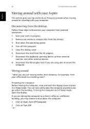
...If you are just moving within the building. or - Moving around or traveling with your Aspire This section gives you go within short distances, for example, from your office desk to ... the desktop Follow these steps to disconnect your computer from the AC adapter. 7 Disconnect the keyboard, pointing device, printer, external monitor, and other external devices. 8 Disconnect the Kensington lock if...consider when moving the computer, close and latch the display cover to place it in progress. 2 Remove any media or compact disc from the drive(s). 3 Shut down the operating system. 4 Turn off ...
...If you are just moving within the building. or - Moving around or traveling with your Aspire This section gives you go within short distances, for example, from your office desk to ... the desktop Follow these steps to disconnect your computer from the AC adapter. 7 Disconnect the keyboard, pointing device, printer, external monitor, and other external devices. 8 Disconnect the Kensington lock if...consider when moving the computer, close and latch the display cover to place it in progress. 2 Remove any media or compact disc from the drive(s). 3 Shut down the operating system. 4 Turn off ...

Acer Aspire 1410, 1810T, and 1810TZ Service Guide
Page 7
... Modules Disassembly Flowchart 44 Removing the Battery Pack 45 Removing the Dummy Card 46 Removing the Hard Disk Drive Module 47 Removing the DIMM Module 50 Removing the WLAN Module 52 Main Unit Disassembly Process 54 Main Unit Disassembly Flowchart 54 Removing the Keyboard 56 Removing the Upper Cover 58 Removing the Button Board 61 Removing the LCD Module 64...
... Modules Disassembly Flowchart 44 Removing the Battery Pack 45 Removing the Dummy Card 46 Removing the Hard Disk Drive Module 47 Removing the DIMM Module 50 Removing the WLAN Module 52 Main Unit Disassembly Process 54 Main Unit Disassembly Flowchart 54 Removing the Keyboard 56 Removing the Upper Cover 58 Removing the Button Board 61 Removing the LCD Module 64...
Acer Aspire 1410, 1810T, and 1810TZ Service Guide
Page 8
...Modules 76 LCD Module Disassembly Process 78 LCD Module Disassembly Flowchart 78 Removing the LCD Bezel 79 Removing the Camera Board 82 Removing the LCD Panel 83 Removing the LCD Brackets 85 Removing the FPC Cable 86 Removing the Antennas 87 LCD Reassembly Procedure 90 Replacing the Antennas 90 Replacing...Common Problems 131 Power On Issue 132 No Display Issue 133 Random Loss of BIOS Settings 134 LCD Failure 135 Built-In Keyboard Failure 136 TouchPad Failure 137 Internal Speaker Failure 138 Internal Microphone Failure 139 HDD Not Operating Correctly 140 USB Failure (Right up...
...Modules 76 LCD Module Disassembly Process 78 LCD Module Disassembly Flowchart 78 Removing the LCD Bezel 79 Removing the Camera Board 82 Removing the LCD Panel 83 Removing the LCD Brackets 85 Removing the FPC Cable 86 Removing the Antennas 87 LCD Reassembly Procedure 90 Replacing the Antennas 90 Replacing...Common Problems 131 Power On Issue 132 No Display Issue 133 Random Loss of BIOS Settings 134 LCD Failure 135 Built-In Keyboard Failure 136 TouchPad Failure 137 Internal Speaker Failure 138 Internal Microphone Failure 139 HDD Not Operating Correctly 140 USB Failure (Right up...

Acer Aspire 1410, 1810T, and 1810TZ Service Guide
Page 53
... want to any of the hardware components. Observe the order of the sequence to avoid damage to remove the Mainboard, you must first remove the Keyboard, and LCD Module then disassemble the inside assembly frame in the succeeding disassembly sections illustrate the entire ...disassembly sequence. Main Screw List Screw Quantity Acer Part Number M2-0.4*2- 2 I(BNI)(NYLOK)(7,0.6)IRON 86.W4107.002 M2.0X2.5-I(BNI)(NYLOK) ...
... want to any of the hardware components. Observe the order of the sequence to avoid damage to remove the Mainboard, you must first remove the Keyboard, and LCD Module then disassemble the inside assembly frame in the succeeding disassembly sections illustrate the entire ...disassembly sequence. Main Screw List Screw Quantity Acer Part Number M2-0.4*2- 2 I(BNI)(NYLOK)(7,0.6)IRON 86.W4107.002 M2.0X2.5-I(BNI)(NYLOK) ...

Acer Aspire 1410, 1810T, and 1810TZ Service Guide
Page 64
Main Unit Disassembly Flowchart Remove External Modules before proceeding Remove Keyboard Remove Upper Cover Remove Button Board Remove LCD Module Remove I/O Board Remove Bluetooth Module Remove LED Board Remove Mainboard Remove Speaker Module Remove CRT Board Remove Thermal Module Remove RTC Battery 54 Chapter 3 During the removal and replacement of components, ensure all available cable channels and clips are used and that the cables are replaced...
Main Unit Disassembly Flowchart Remove External Modules before proceeding Remove Keyboard Remove Upper Cover Remove Button Board Remove LCD Module Remove I/O Board Remove Bluetooth Module Remove LED Board Remove Mainboard Remove Speaker Module Remove CRT Board Remove Thermal Module Remove RTC Battery 54 Chapter 3 During the removal and replacement of components, ensure all available cable channels and clips are used and that the cables are replaced...

Acer Aspire 1410, 1810T, and 1810TZ Service Guide
Page 66
...45. 2. Removing the Keyboard IMPORTANT: The keyboard is easily warped or damaged during the removal process. NOTE: The keyboard will spring up slightly when all retaining clips are unlocked. 56 Chapter 3 See "Removing the Battery Pack" on page 47. 3. See "Removing the WLAN Module" on page 50. 4. See "Removing the DIMM... Module" on page 52. 5. Using the plastic pry, press in the four latches along the top of the keyboard to prevent damage. 1. Take...
...45. 2. Removing the Keyboard IMPORTANT: The keyboard is easily warped or damaged during the removal process. NOTE: The keyboard will spring up slightly when all retaining clips are unlocked. 56 Chapter 3 See "Removing the Battery Pack" on page 47. 3. See "Removing the WLAN Module" on page 50. 4. See "Removing the DIMM... Module" on page 52. 5. Using the plastic pry, press in the four latches along the top of the keyboard to prevent damage. 1. Take...

Acer Aspire 1410, 1810T, and 1810TZ Service Guide
Page 68
Screw List Step Upper Cover Disassembly Size M2*2.5 M2*3 M2*5 Quantity 3 (blue call out) 3 (green call out) 6 (red call out) Screw Type 58 Chapter 3 See "Removing the Keyboard" on page 56. 2. Remove the twelve screws in the upper cover. Removing the Upper Cover 1. Disconnect the button board FCC from the main board by unlocking the FCC cable and pulling away. 3.
Screw List Step Upper Cover Disassembly Size M2*2.5 M2*3 M2*5 Quantity 3 (blue call out) 3 (green call out) 6 (red call out) Screw Type 58 Chapter 3 See "Removing the Keyboard" on page 56. 2. Remove the twelve screws in the upper cover. Removing the Upper Cover 1. Disconnect the button board FCC from the main board by unlocking the FCC cable and pulling away. 3.

Acer Aspire 1410, 1810T, and 1810TZ Service Guide
Page 235
... mode hotkey 13 Hot Keys 11 I Indicators 9 Intermittent Problems 142 Internal Microphone Failure 139 Internal Speaker Failure 138 J Jumper and Connector Locations 147 K Keyboard Removing 56 Keyboard Failure 136 L LCD Bezel Removing 79, 98 LCD Brackets Removing 86 LCD Cable Removing 86 LCD Failure 135 LCD Module Removing 113 LCD Module Disassembly Flowchart 78 LCD Panel 225
... mode hotkey 13 Hot Keys 11 I Indicators 9 Intermittent Problems 142 Internal Microphone Failure 139 Internal Speaker Failure 138 J Jumper and Connector Locations 147 K Keyboard Removing 56 Keyboard Failure 136 L LCD Bezel Removing 79, 98 LCD Brackets Removing 86 LCD Cable Removing 86 LCD Failure 135 LCD Module Removing 113 LCD Module Disassembly Flowchart 78 LCD Panel 225

