AL1751 Service Guide
Page 5
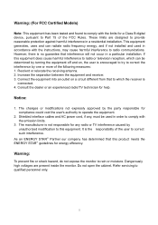
...void the user's authority to this product meets the ENERGY STAR® guidelines for energy efficiency. These limits are present inside the monitor. Increase the separation between the equipment and receiver. 3. Connect the equipment into an outlet on , the user is not responsible for...Consult the dealer or an experienced radio/TV technician for help. Warning: To prevent fire or shock hazard, do not expose the monitor to radio communications. This equipment generates, uses and can be determined by unauthorized modification to operate the equipment. 2. Shielded interface cables ...
...void the user's authority to this product meets the ENERGY STAR® guidelines for energy efficiency. These limits are present inside the monitor. Increase the separation between the equipment and receiver. 3. Connect the equipment into an outlet on , the user is not responsible for...Consult the dealer or an experienced radio/TV technician for help. Warning: To prevent fire or shock hazard, do not expose the monitor to radio communications. This equipment generates, uses and can be determined by unauthorized modification to operate the equipment. 2. Shielded interface cables ...
AL1751 Service Guide
Page 6
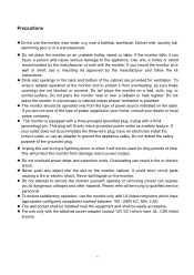
...sold with the attached power adapter (output 12V DC) which have an electrician install the correct outlet, or use an adapter to service the monitor yourself; Do not overload power strips and extension cords. near the equipment and shall be installed near a bathtub, washbowl, kitchen sink, laundry ... does not accommodate the three-wire plug, have appropriate configured receptacles marked between 100 - 240V AC, Min. 3.5A. Do not place the monitor on an unstable trolley, stand, or table. This plug will not be operated only from the type of the grounded plug. Precautions Do not...
...sold with the attached power adapter (output 12V DC) which have an electrician install the correct outlet, or use an adapter to service the monitor yourself; Do not overload power strips and extension cords. near the equipment and shall be installed near a bathtub, washbowl, kitchen sink, laundry ... does not accommodate the three-wire plug, have appropriate configured receptacles marked between 100 - 240V AC, Min. 3.5A. Do not place the monitor on an unstable trolley, stand, or table. This plug will not be operated only from the type of the grounded plug. Precautions Do not...
AL1751 Service Guide
Page 7
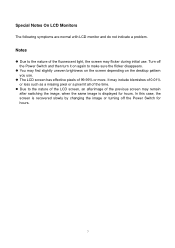
... following symptoms are normal with LCD monitor and do not indicate a problem. It may include blemishes of 0.01% or less such as a missing pixel or a pixel lit all of the fluorescent light, ...
... following symptoms are normal with LCD monitor and do not indicate a problem. It may include blemishes of 0.01% or less such as a missing pixel or a pixel lit all of the fluorescent light, ...
AL1751 Service Guide
Page 8
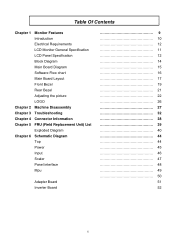
Table Of Contents Chapter 1 Monitor Features Introduction Electrical Requirements LCD Monitor General Specification LCD Panel Specification Block Diagram Main Board Diagram Software Flow chart Main Board Layout Front Bezel Rear Bezel Adjusting the picture LOGO Chapter 2 ...
Table Of Contents Chapter 1 Monitor Features Introduction Electrical Requirements LCD Monitor General Specification LCD Panel Specification Block Diagram Main Board Diagram Software Flow chart Main Board Layout Front Bezel Rear Bezel Adjusting the picture LOGO Chapter 2 ...

AL1751 Service Guide
Page 9
... is 50k hours or more desktop space, and comparing to general 15 pin D-sub VGA connector and 24 pin DVI connector. Chapter 1 Monitor Features Introduction Scope This specification defines the requirements for the 17" MICRO-PROCESSOR based Multi-mode supported high resolution color LCD...plug & play function. It is designed with the latest LCD technology to provide a performance oriented product with OSD control to drive a pair of AL1751 Panel Signal Interface Sync Type Color Temp User Adjust DDC Speaker Headphone Jack Microphone Jack USB Hub Tilt / Swivel 17" SEC LTM170EU-L21 D-SUB DVI...
... is 50k hours or more desktop space, and comparing to general 15 pin D-sub VGA connector and 24 pin DVI connector. Chapter 1 Monitor Features Introduction Scope This specification defines the requirements for the 17" MICRO-PROCESSOR based Multi-mode supported high resolution color LCD...plug & play function. It is designed with the latest LCD technology to provide a performance oriented product with OSD control to drive a pair of AL1751 Panel Signal Interface Sync Type Color Temp User Adjust DDC Speaker Headphone Jack Microphone Jack USB Hub Tilt / Swivel 17" SEC LTM170EU-L21 D-SUB DVI...
AL1751 Service Guide
Page 10
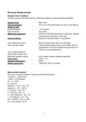
.../white balance and Blue/white balance control : Power input : Ambient temperature : Analog input mode : Set to Factory preset value (cut off raster) T Set to the monitor under the following conditions, unless otherwise specified. In the center (unless otherwise specified) 230V 5Ċ 20+5¥ 1280x1024, 60 Hz, all white Measurement systems The...
.../white balance and Blue/white balance control : Power input : Ambient temperature : Analog input mode : Set to Factory preset value (cut off raster) T Set to the monitor under the following conditions, unless otherwise specified. In the center (unless otherwise specified) 230V 5Ċ 20+5¥ 1280x1024, 60 Hz, all white Measurement systems The...
AL1751 Service Guide
Page 14
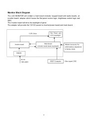
Flat Panel and CCFL backlight Inverter board Adapter AC-IN 100V-240V Main Board (Include: Audio board, keyboard) RS232 Connector For white balance adjustment in factory mode HOST Computer Video signal, DDC 14 The adapter will drive the backlight of panel. CCFL Drive. The Inverter board will provide the 12V DC-power to inverter/power board and main board. Monitor Block Diagram The LCD MONITOR will contain a main board (include: keypad board and audio board), an inverter board, adapter which house the flat panel control logic, brightness control logic and DDC.
Flat Panel and CCFL backlight Inverter board Adapter AC-IN 100V-240V Main Board (Include: Audio board, keyboard) RS232 Connector For white balance adjustment in factory mode HOST Computer Video signal, DDC 14 The adapter will drive the backlight of panel. CCFL Drive. The Inverter board will provide the 12V DC-power to inverter/power board and main board. Monitor Block Diagram The LCD MONITOR will contain a main board (include: keypad board and audio board), an inverter board, adapter which house the flat panel control logic, brightness control logic and DDC.
AL1751 Service Guide
Page 26
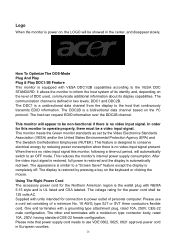
...accessory power cord for the power cord shall be a video input signal. Please note that continuously transmits EDID information. This monitor meets the Green monitor standards as set consisting of personal computer: Please use VDE 0602, 0625, 0821 approval power cord in European counties. 26...display is restored by reducing power consumption when there is no video input signal. The other end terminates with units intended for this monitor, following a time-out period, will automatically switch to the VESA DDC STANDARD. The communication channel is defined in the center, ...
...accessory power cord for the power cord shall be a video input signal. Please note that continuously transmits EDID information. This monitor meets the Green monitor standards as set consisting of personal computer: Please use VDE 0602, 0625, 0821 approval power cord in European counties. 26...display is restored by reducing power consumption when there is no video input signal. The other end terminates with units intended for this monitor, following a time-out period, will automatically switch to the VESA DDC STANDARD. The communication channel is defined in the center, ...
AL1751 Service Guide
Page 27
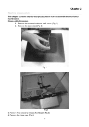
Remove four screws to assemble the monitor for maintenance. Chapter 2 Machine Disassembly This chapter contains step-by-step procedures on how to release front bezel. (Fig 3) 4. Remove the base stand (Fig 2) Fig 1 Fig2 3. Remove the hinge cap. (Fig 4) 27 Disassembly Procedure 1. Remove two screws to release back cover. (Fig 1). 2.
Remove four screws to assemble the monitor for maintenance. Chapter 2 Machine Disassembly This chapter contains step-by-step procedures on how to release front bezel. (Fig 3) 4. Remove the base stand (Fig 2) Fig 1 Fig2 3. Remove the hinge cap. (Fig 4) 27 Disassembly Procedure 1. Remove two screws to release back cover. (Fig 1). 2.
AL1751 Service Guide
Page 38
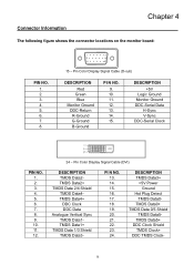
... Clock DDC Data Analogue Vertical Sync TMDS Data1TMDS Data1+ TMDS Data 1/3 Shield TMDS Data3- Pin Color Display Signal Cable (D-sub) DESCRIPTION Red Green Blue Monitor Ground DDC-Return R-Ground G-Ground B-Ground PI N NO. 9. 10. 11. 12. 13. 14. 15. DESCRIPTION TMDS Data3+ +5V Power ...Ground Hot Plug Detect TMDS Data0- Connector Information Chapter 4 The following figure shows the connector locations on the monitor board: PIN NO. 1. 2. 3. 4. 5. 6. 7. 8. 1 5 6 10 11 15 15 - TMDS Data0+ TMDS Data 0/5 Shield TMDS Data5TMDS Data5+ DDC Clock Shield...
... Clock DDC Data Analogue Vertical Sync TMDS Data1TMDS Data1+ TMDS Data 1/3 Shield TMDS Data3- Pin Color Display Signal Cable (D-sub) DESCRIPTION Red Green Blue Monitor Ground DDC-Return R-Ground G-Ground B-Ground PI N NO. 9. 10. 11. 12. 13. 14. 15. DESCRIPTION TMDS Data3+ +5V Power ...Ground Hot Plug Detect TMDS Data0- Connector Information Chapter 4 The following figure shows the connector locations on the monitor board: PIN NO. 1. 2. 3. 4. 5. 6. 7. 8. 1 5 6 10 11 15 15 - TMDS Data0+ TMDS Data 0/5 Shield TMDS Data5TMDS Data5+ DDC Clock Shield...


