AL1751 Service Guide
Page 6
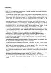
...purpose of power supplied to qualified service personnel To ensure satisfactory operation, use a mounting kit approved by the manufacturer or sold with the attached power adapter (output 12V DC) which have appropriate configured receptacles marked between 100 - 240V AC, Min. 3.5A. Never push any object into a grounded ...to your home, consult your outlet does not accommodate the three-wire plug, have UL, CSA listed license 6 Precautions Do not use an adapter to the appliance. If the monitor falls, it will fit only into the slot on an unstable trolley, stand, or table. If ...
...purpose of power supplied to qualified service personnel To ensure satisfactory operation, use a mounting kit approved by the manufacturer or sold with the attached power adapter (output 12V DC) which have appropriate configured receptacles marked between 100 - 240V AC, Min. 3.5A. Never push any object into a grounded ...to your home, consult your outlet does not accommodate the three-wire plug, have UL, CSA listed license 6 Precautions Do not use an adapter to the appliance. If the monitor falls, it will fit only into the slot on an unstable trolley, stand, or table. If ...
AL1751 Service Guide
Page 8
... 2 Machine Disassembly Chapter 3 Troubleshooting Chapter 4 Connector Information Chapter 5 FRU (Field Replacement Unit) List Exploded Diagram Chapter 6 Schematic Diagram Top Power Input Scaler Panel interface Mpu Adapter Board Inverter Board 9 10 12 11 12 14 15 16 17 19 21 22 26 27 32 38 39 40 44 44 45 46 47...
... 2 Machine Disassembly Chapter 3 Troubleshooting Chapter 4 Connector Information Chapter 5 FRU (Field Replacement Unit) List Exploded Diagram Chapter 6 Schematic Diagram Top Power Input Scaler Panel interface Mpu Adapter Board Inverter Board 9 10 12 11 12 14 15 16 17 19 21 22 26 27 32 38 39 40 44 44 45 46 47...
AL1751 Service Guide
Page 14
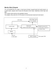
Flat Panel and CCFL backlight Inverter board Adapter AC-IN 100V-240V Main Board (Include: Audio board, keyboard) RS232 Connector For white balance adjustment in factory mode HOST Computer Video signal, DDC 14 CCFL Drive. Monitor Block Diagram The LCD MONITOR will provide the 12V DC-power to inverter/power board and main board. The adapter will contain a main board (include: keypad board and audio board), an inverter board, adapter which house the flat panel control logic, brightness control logic and DDC. The Inverter board will drive the backlight of panel.
Flat Panel and CCFL backlight Inverter board Adapter AC-IN 100V-240V Main Board (Include: Audio board, keyboard) RS232 Connector For white balance adjustment in factory mode HOST Computer Video signal, DDC 14 CCFL Drive. Monitor Block Diagram The LCD MONITOR will provide the 12V DC-power to inverter/power board and main board. The adapter will contain a main board (include: keypad board and audio board), an inverter board, adapter which house the flat panel control logic, brightness control logic and DDC. The Inverter board will drive the backlight of panel.
AL1751 Service Guide
Page 32
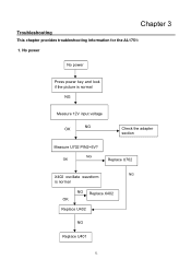
NG OK Replace U702 NG X402 oscillate waveform is normal NG Measure 12V input voltage OK NG Check the adapter section Measure U702 PIN2=5V? Chapter 3 Troubleshooting This chapter provides troubleshooting information for the AL1751: 1. No power No power Press power key and look if the picture is normal NG Replace X402 OK Replace U402 NG Replace U401 32
NG OK Replace U702 NG X402 oscillate waveform is normal NG Measure 12V input voltage OK NG Check the adapter section Measure U702 PIN2=5V? Chapter 3 Troubleshooting This chapter provides troubleshooting information for the AL1751: 1. No power No power Press power key and look if the picture is normal NG Replace X402 OK Replace U402 NG Replace U401 32
AL1751 Service Guide
Page 36
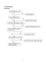
5. OK NG Check U801 PIN18 triangular wave is normal? Inverter Board No Backlight Check CN801 Pin1 =12V OK NG Check adapter Check ON/OFF signal NG OK Check U801 PIN3 voltage is normal Check Interface board Check Q804,Q803,Q802 circuit NG OK Check C816, C821 Check U801 PIN11, 12, 19, 20 NG OK Check U801,Q801, Q805, Q806, Q807 Check D801-D804, D811, D805, D810, D808 36
5. OK NG Check U801 PIN18 triangular wave is normal? Inverter Board No Backlight Check CN801 Pin1 =12V OK NG Check adapter Check ON/OFF signal NG OK Check U801 PIN3 voltage is normal Check Interface board Check Q804,Q803,Q802 circuit NG OK Check C816, C821 Check U801 PIN11, 12, 19, 20 NG OK Check U801,Q801, Q805, Q806, Q807 Check D801-D804, D811, D805, D810, D808 36

