
AL1751 Service Guide
Page 3
... any electronic machine readable form without notice. ACER AL1751 Service Manual Printed in part, be copied, photocopied, reproduced, translated, or converted to change without prior written permission of LiteOn Technology Corp. Intel is ". Should the programs prove defective following their respective holders. 3 Acer is subject to any particular purpose. Acer Incorporated makes no representations or warranties, either expressed or...
... any electronic machine readable form without notice. ACER AL1751 Service Manual Printed in part, be copied, photocopied, reproduced, translated, or converted to change without prior written permission of LiteOn Technology Corp. Intel is ". Should the programs prove defective following their respective holders. 3 Acer is subject to any particular purpose. Acer Incorporated makes no representations or warranties, either expressed or...
AL1751 Service Guide
Page 4
... list of their respective owners. All other trademarks are used in the printed Service Guide. You MUST use the list provided by your Acer office may have decided to order FRU parts for whatever reason, a part number change is a registered trademark of additional information related to the current topic. Gives precautionary measures to avoid possible hardware or software problems. Remind you with...
... list of their respective owners. All other trademarks are used in the printed Service Guide. You MUST use the list provided by your Acer office may have decided to order FRU parts for whatever reason, a part number change is a registered trademark of additional information related to the current topic. Gives precautionary measures to avoid possible hardware or software problems. Remind you with...
AL1751 Service Guide
Page 5
... a Class B digital device, pursuant to this equipment. Warning: To prevent fire or shock hazard, do not expose the monitor to which can radiate radio frequency energy, and if not installed and used in accordance with the emission limits. 3. If this product meets the ENERGY STAR® guidelines for energy efficiency. Shielded interface cables and AC power cord, if...
... a Class B digital device, pursuant to this equipment. Warning: To prevent fire or shock hazard, do not expose the monitor to which can radiate radio frequency energy, and if not installed and used in accordance with the emission limits. 3. If this product meets the ENERGY STAR® guidelines for energy efficiency. Shielded interface cables and AC power cord, if...
AL1751 Service Guide
Page 6
... follow the kit instructions. The monitor is provided. Do not defeat the safety purpose of time. Do not overload power strips and extension cords. Overloading can result in a bookcase or cabinet unless proper ventilation is equipped with a three-pronged grounded plug, a plug with the monitor. For use an adapter to qualified service personnel To ensure satisfactory operation, use a mounting kit approved by...
... follow the kit instructions. The monitor is provided. Do not defeat the safety purpose of time. Do not overload power strips and extension cords. Overloading can result in a bookcase or cabinet unless proper ventilation is equipped with a three-pronged grounded plug, a plug with the monitor. For use an adapter to qualified service personnel To ensure satisfactory operation, use a mounting kit approved by...
AL1751 Service Guide
Page 7
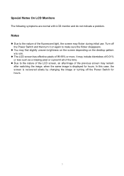
... switching the image, when the same image is recovered slowly by changing the image or turning off the Power Switch and then turn it on the desktop pattern you use . Turn off the Power Switch for hours. In this case, the screen is displayed for hours. 7 The LCD screen has effective pixels of the time. Special Notes On LCD Monitors The following symptoms are normal with LCD monitor and do not indicate a problem...
... switching the image, when the same image is recovered slowly by changing the image or turning off the Power Switch and then turn it on the desktop pattern you use . Turn off the Power Switch for hours. In this case, the screen is displayed for hours. 7 The LCD screen has effective pixels of the time. Special Notes On LCD Monitors The following symptoms are normal with LCD monitor and do not indicate a problem...
AL1751 Service Guide
Page 8
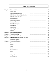
Table Of Contents Chapter 1 Monitor Features Introduction Electrical Requirements LCD Monitor General Specification LCD Panel Specification Block Diagram Main Board Diagram Software Flow chart Main Board Layout Front Bezel Rear Bezel Adjusting the picture LOGO Chapter 2 Machine Disassembly Chapter 3 Troubleshooting Chapter 4 Connector Information Chapter 5 FRU (Field Replacement Unit) List Exploded Diagram Chapter 6 Schematic Diagram Top Power Input Scaler Panel interface Mpu Adapter Board Inverter Board 9 10 12 11 12 14 15 16 17 19 21 22 26 27...
Table Of Contents Chapter 1 Monitor Features Introduction Electrical Requirements LCD Monitor General Specification LCD Panel Specification Block Diagram Main Board Diagram Software Flow chart Main Board Layout Front Bezel Rear Bezel Adjusting the picture LOGO Chapter 2 Machine Disassembly Chapter 3 Troubleshooting Chapter 4 Connector Information Chapter 5 FRU (Field Replacement Unit) List Exploded Diagram Chapter 6 Schematic Diagram Top Power Input Scaler Panel interface Mpu Adapter Board Inverter Board 9 10 12 11 12 14 15 16 17 19 21 22 26 27...

AL1751 Service Guide
Page 9
... a build-in stereo audio amplifier with OSD control to drive a pair of AL1751 Panel Signal Interface Sync Type Color Temp User Adjust DDC Speaker Headphone Jack Microphone Jack USB Hub Tilt / Swivel 17" SEC LTM170EU-L21 D-SUB DVI Separate / Compatible Support DDC2B 1.5W + 1.5W (Rated power) 3.5mm stereo phone jack, green color No Not support Yes / No 9 Description The LCD monitor is designed with no radiation. It also supports VESA DPMS power management and plug & play function...
... a build-in stereo audio amplifier with OSD control to drive a pair of AL1751 Panel Signal Interface Sync Type Color Temp User Adjust DDC Speaker Headphone Jack Microphone Jack USB Hub Tilt / Swivel 17" SEC LTM170EU-L21 D-SUB DVI Separate / Compatible Support DDC2B 1.5W + 1.5W (Rated power) 3.5mm stereo phone jack, green color No Not support Yes / No 9 Description The LCD monitor is designed with no radiation. It also supports VESA DPMS power management and plug & play function...
AL1751 Service Guide
Page 10
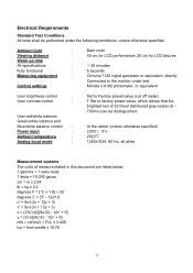
... All tests shall be distinguished. Control settings Minolta CA100 photometer, or equivalent User brightness control : User contrast control : User red/white balance, Green/white balance and Blue/white balance control : Power input : Ambient temperature : Analog input mode : Set to Factory preset value (cut off raster) T Set to the monitor under the following conditions, unless otherwise specified. In the center (unless otherwise specified) 230V 5Ċ 20+5¥ 1280x1024, 60 Hz, all white Measurement systems The units of...
... All tests shall be distinguished. Control settings Minolta CA100 photometer, or equivalent User brightness control : User contrast control : User red/white balance, Green/white balance and Blue/white balance control : Power input : Ambient temperature : Analog input mode : Set to Factory preset value (cut off raster) T Set to the monitor under the following conditions, unless otherwise specified. In the center (unless otherwise specified) 230V 5Ċ 20+5¥ 1280x1024, 60 Hz, all white Measurement systems The units of...
AL1751 Service Guide
Page 12
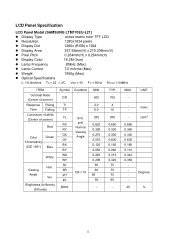
... % 12 LCD Panel Specification LCD Panel Model (SAMSUNG LTM170EU-L21) Display Type active matrix color TFT LCD Resolution 1280x1024 pixels Display Dot 1280x (RGB) x 1024 Display Area 337.92mm(H) x 270.336mm(V) Pixel Pitch 0.264mm(H) x 0.264mm(V) Display Color 16.2M (true) Lamp Frequency 80kHz (Max) Lamp Current 7.0 mArms (Max) Weight 1950g (Max) Optical Specifications IL = 6.5mArms Ta = 25 2¢C VDD = 5V FV = 60Hz FDCLK = 54MHz ITEM Contrast Ratio (Center of screen) Response Rising...
... % 12 LCD Panel Specification LCD Panel Model (SAMSUNG LTM170EU-L21) Display Type active matrix color TFT LCD Resolution 1280x1024 pixels Display Dot 1280x (RGB) x 1024 Display Area 337.92mm(H) x 270.336mm(V) Pixel Pitch 0.264mm(H) x 0.264mm(V) Display Color 16.2M (true) Lamp Frequency 80kHz (Max) Lamp Current 7.0 mArms (Max) Weight 1950g (Max) Optical Specifications IL = 6.5mArms Ta = 25 2¢C VDD = 5V FV = 60Hz FDCLK = 54MHz ITEM Contrast Ratio (Center of screen) Response Rising...
AL1751 Service Guide
Page 14
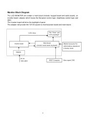
Flat Panel and CCFL backlight Inverter board Adapter AC-IN 100V-240V Main Board (Include: Audio board, keyboard) RS232 Connector For white balance adjustment in factory mode HOST Computer Video signal, DDC 14 The adapter will contain a main board (include: keypad board and audio board), an inverter board, adapter which house the flat panel control logic, brightness control logic and DDC. Monitor Block Diagram The LCD MONITOR will provide the 12V DC-power to inverter/power board and main board. CCFL Drive. The Inverter board will drive the backlight of panel.
Flat Panel and CCFL backlight Inverter board Adapter AC-IN 100V-240V Main Board (Include: Audio board, keyboard) RS232 Connector For white balance adjustment in factory mode HOST Computer Video signal, DDC 14 The adapter will contain a main board (include: keypad board and audio board), an inverter board, adapter which house the flat panel control logic, brightness control logic and DDC. Monitor Block Diagram The LCD MONITOR will provide the 12V DC-power to inverter/power board and main board. CCFL Drive. The Inverter board will drive the backlight of panel.
AL1751 Service Guide
Page 16
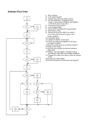
Scalar initializes. 10) In standby mode? 11) Update the lifetime of brightness from analog or digital port? 16) Display " No Input Signal " message. Software Flow Chart 1 2 Y 3 N 4 5 N Y 6 7 N 8 Y 9 1) MCU initialize. 2) Is the eeprom blank? 3) Program the eeprom by default values. 4) Get the PWM value of back light. 12) Check the analog and digital port, are there any signals coming? 13) Does the scalar send out a interrupt request? 14) Wake up...
Scalar initializes. 10) In standby mode? 11) Update the lifetime of brightness from analog or digital port? 16) Display " No Input Signal " message. Software Flow Chart 1 2 Y 3 N 4 5 N Y 6 7 N 8 Y 9 1) MCU initialize. 2) Is the eeprom blank? 3) Program the eeprom by default values. 4) Get the PWM value of back light. 12) Check the analog and digital port, are there any signals coming? 13) Does the scalar send out a interrupt request? 14) Wake up...
AL1751 Service Guide
Page 26
... is no video input signal. The DDC1 is a unidirectional data channel from the display to the host that power supply cord needs to the VESA DDC STANDARD. After the video input signal is restored, full power is restored and the display is a bidirectional data channel based on the I²C protocol. Using The Right Power Cord The accessory power cord for this monitor, following a time-out period, will automatically switch to power outlet of...
... is no video input signal. The DDC1 is a unidirectional data channel from the display to the host that power supply cord needs to the VESA DDC STANDARD. After the video input signal is restored, full power is restored and the display is a bidirectional data channel based on the I²C protocol. Using The Right Power Cord The accessory power cord for this monitor, following a time-out period, will automatically switch to power outlet of...
AL1751 Service Guide
Page 27
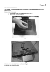
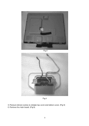
Chapter 2 Machine Disassembly This chapter contains step-by-step procedures on how to release front bezel. (Fig 3) 4. Remove the hinge cap. (Fig 4) 27 Remove four screws to assemble the monitor for maintenance. Disassembly Procedure 1. Remove two screws to release back cover. (Fig 1). 2. Remove the base stand (Fig 2) Fig 1 Fig2 3.
Chapter 2 Machine Disassembly This chapter contains step-by-step procedures on how to release front bezel. (Fig 3) 4. Remove the hinge cap. (Fig 4) 27 Remove four screws to assemble the monitor for maintenance. Disassembly Procedure 1. Remove two screws to release back cover. (Fig 1). 2. Remove the base stand (Fig 2) Fig 1 Fig2 3.
AL1751 Service Guide
Page 28
Remove eleven screws to release top cover and bottom cover. (Fig 5) 6. Fig 3 Fig 4 5. Remove the main board. (Fig 6) 28
Remove eleven screws to release top cover and bottom cover. (Fig 5) 6. Fig 3 Fig 4 5. Remove the main board. (Fig 6) 28
AL1751 Service Guide
Page 32
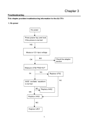
Chapter 3 Troubleshooting This chapter provides troubleshooting information for the AL1751: 1. NG OK Replace U702 NG X402 oscillate waveform is normal NG Measure 12V input voltage OK NG Check the adapter section Measure U702 PIN2=5V? No power No power Press power key and look if the picture is normal NG Replace X402 OK Replace U402 NG Replace U401 32
Chapter 3 Troubleshooting This chapter provides troubleshooting information for the AL1751: 1. NG OK Replace U702 NG X402 oscillate waveform is normal NG Measure 12V input voltage OK NG Check the adapter section Measure U702 PIN2=5V? No power No power Press power key and look if the picture is normal NG Replace X402 OK Replace U402 NG Replace U401 32
AL1751 Service Guide
Page 33
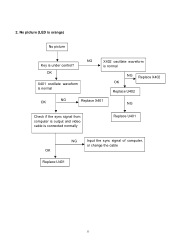
No picture (LED is orange) No picture NG Key is connected normally Replace U401 NG OK Replace U401 Input the sync signal of computer, or change the cable 33 OK X401 oscillate waveform is normal X402 oscillate waveform is normal NG Replace X402 OK Replace U402 OK NG Replace X401 NG Check if the sync signal from computer is output and video cable is under control? 2.
No picture (LED is orange) No picture NG Key is connected normally Replace U401 NG OK Replace U401 Input the sync signal of computer, or change the cable 33 OK X401 oscillate waveform is normal X402 oscillate waveform is normal NG Replace X402 OK Replace U402 OK NG Replace X401 NG Check if the sync signal from computer is output and video cable is under control? 2.
AL1751 Service Guide
Page 35
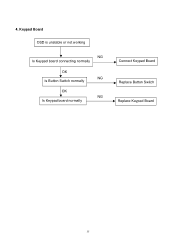
Keypad Board OSD is unstable or not working NG Is Keypad board connecting normally OK NG Is Button Switch normally OK NG Is Keypad board normally Connect Keypad Board Replace Button Switch Replace Keypad Board 35 4.
Keypad Board OSD is unstable or not working NG Is Keypad board connecting normally OK NG Is Button Switch normally OK NG Is Keypad board normally Connect Keypad Board Replace Button Switch Replace Keypad Board 35 4.
AL1751 Service Guide
Page 37
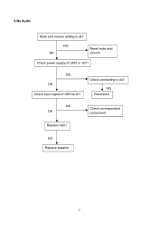
6.No Audio Mute and volume setting is ok? NG Reconnect NG OK Check correspondent component Replace U601 NG Replace speaker 37 Check connecting is ok? NG OK Reset mute and volume Check power supply of U601is ok? NG OK Check input signal of U601 is 12V?
6.No Audio Mute and volume setting is ok? NG Reconnect NG OK Check correspondent component Replace U601 NG Replace speaker 37 Check connecting is ok? NG OK Reset mute and volume Check power supply of U601is ok? NG OK Check input signal of U601 is 12V?
AL1751 Service Guide
Page 38
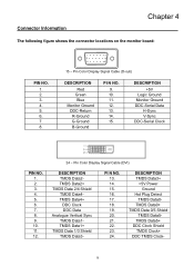
... Clock DDC Data Analogue Vertical Sync TMDS Data1TMDS Data1+ TMDS Data 1/3 Shield TMDS Data3- Pin Color Display Signal Cable (D-sub) DESCRIPTION Red Green Blue Monitor Ground DDC-Return R-Ground G-Ground B-Ground PI N NO. 9. 10. 11. 12. 13. 14. 15. DESCRIPTION TMDS Data3+ +5V Power Ground Hot Plug Detect TMDS Data0- DESCRIPTION +5V Logic Ground Monitor Ground DDC-Serial Data H-Sync V-Sync DDC-Serial Clock PIN NO. 1. 2. 3. 4. 5. 6. 7. 8. 9. 10...
... Clock DDC Data Analogue Vertical Sync TMDS Data1TMDS Data1+ TMDS Data 1/3 Shield TMDS Data3- Pin Color Display Signal Cable (D-sub) DESCRIPTION Red Green Blue Monitor Ground DDC-Return R-Ground G-Ground B-Ground PI N NO. 9. 10. 11. 12. 13. 14. 15. DESCRIPTION TMDS Data3+ +5V Power Ground Hot Plug Detect TMDS Data0- DESCRIPTION +5V Logic Ground Monitor Ground DDC-Serial Data H-Sync V-Sync DDC-Serial Clock PIN NO. 1. 2. 3. 4. 5. 6. 7. 8. 9. 10...
AL1751 Service Guide
Page 39
... printed Service Guide. You MUST use the local FRU list provided by your Acer office may have a DIFFERENT part number code from those given in the FRU list of this chapter whenever ordering for parts to repair or for repair and service of AL1922.Refer to return it. 39 For whatever reasons a part number change is made, it properly, or follow the rules set by...
... printed Service Guide. You MUST use the local FRU list provided by your Acer office may have a DIFFERENT part number code from those given in the FRU list of this chapter whenever ordering for parts to repair or for repair and service of AL1922.Refer to return it. 39 For whatever reasons a part number change is made, it properly, or follow the rules set by...


