User Manual
Page 1
All rights reserved. 1 P43D1600Twins-1394 / P43D1600Twins / P43Twins1600 User Manual Version 1.0 Published May 2008 Copyright©2008 ASRock INC.
All rights reserved. 1 P43D1600Twins-1394 / P43D1600Twins / P43Twins1600 User Manual Version 1.0 Published May 2008 Copyright©2008 ASRock INC.
User Manual
Page 2
... purchaser for informational use only and subject to the contents of this manual, ASRock does not provide warranty of any defect or error in the manual or product. Disclaimer: Specifications and information contained in this manual are used only for loss of profits, loss of business, loss of..., or consequential damages (including damages for identification or explanation and to the owners' benefit, without written consent of ASRock Inc. Copyright Notice: No part of this manual may be reproduced, transcribed, transmitted, or translated in any language, in any form or by any means, except...
... purchaser for informational use only and subject to the contents of this manual, ASRock does not provide warranty of any defect or error in the manual or product. Disclaimer: Specifications and information contained in this manual are used only for loss of profits, loss of business, loss of..., or consequential damages (including damages for identification or explanation and to the owners' benefit, without written consent of ASRock Inc. Copyright Notice: No part of this manual may be reproduced, transcribed, transmitted, or translated in any language, in any form or by any means, except...
User Manual
Page 5
... Power Cable (Optional) One HDMI_SPDIF Cable (Optional) One "ASRock 1394_SPDIF I/O" I/O Panel Shield (P43D1600Twins-1394) One "ASRock SPDIF I/O" I/O Panel Shield (P43D1600Twins / P43Twins1600) 5 ASRock website http://www.asrock.com If you require technical support related to this manual occur, the updated version will be updated, the content of this manual, chapter 1 and 2 contain introduction of the motherboard and step...
... Power Cable (Optional) One HDMI_SPDIF Cable (Optional) One "ASRock 1394_SPDIF I/O" I/O Panel Shield (P43D1600Twins-1394) One "ASRock SPDIF I/O" I/O Panel Shield (P43D1600Twins / P43Twins1600) 5 ASRock website http://www.asrock.com If you require technical support related to this manual occur, the updated version will be updated, the content of this manual, chapter 1 and 2 contain introduction of the motherboard and step...
User Manual
Page 19
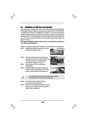
... page 11/12, No. 2). Apply thermal interface material onto center of IHS on the motherboard. Step 5. Connect fan header with tie-wrap to the instruction manuals of your CPU fan and heatsink. Secure excess cable with the CPU fan connector on the socket surface. Place the heatsink onto the socket. Repeat...
... page 11/12, No. 2). Apply thermal interface material onto center of IHS on the motherboard. Step 5. Connect fan header with tie-wrap to the instruction manuals of your CPU fan and heatsink. Secure excess cable with the CPU fan connector on the socket surface. Place the heatsink onto the socket. Repeat...
User Manual
Page 27
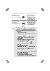
...'t need to OUT2_L. For Windows® 2000 / XP / XP 64-bit OS: Please select "Front Mic" as below: A. Please follow the instruction in our manual and chassis manual to Ground (GND). For Windows® 2000 / XP / XP 64-bit OS: Click "Audio I/O", select "Connector Settings" , choose "Disable front panel jack detection", and...
...'t need to OUT2_L. For Windows® 2000 / XP / XP 64-bit OS: Please select "Front Mic" as below: A. Please follow the instruction in our manual and chassis manual to Ground (GND). For Windows® 2000 / XP / XP 64-bit OS: Click "Audio I/O", select "Connector Settings" , choose "Disable front panel jack detection", and...
User Manual
Page 30
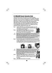
... the HDMI_SPDIF cable to the motherboard and the HDMI VGA card according to the HDMI_SPDIF connector of HDMI_SPDIF cable to the VGA card user manual for detailed connection procedures. Please choose the appropriate white end according to the same pin definition. Otherwise, the motherboard and the VGA card...fan connector of HDMI VGA card vendor. For example, this motherboard. Please do not connect the white end of HDMI_SPDIF cable to the user manual of PCI Express VGA card. Install the HDMI VGA card to the• PCI Express Graphics slot on HDMI VGA card, please refer ...
... the HDMI_SPDIF cable to the motherboard and the HDMI VGA card according to the HDMI_SPDIF connector of HDMI_SPDIF cable to the VGA card user manual for detailed connection procedures. Please choose the appropriate white end according to the same pin definition. Otherwise, the motherboard and the VGA card...fan connector of HDMI VGA card vendor. For example, this motherboard. Please do not connect the white end of HDMI_SPDIF cable to the user manual of PCI Express VGA card. Install the HDMI VGA card to the• PCI Express Graphics slot on HDMI VGA card, please refer ...
User Manual
Page 36
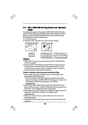
.../ SATAII Hot Plug cannot be damaged under the Hot Plug operation. 3. Below operation procedure is available on our website: www.asrock.com 2. Make sure to use the SATA power cable & data cable, which are from your SATA / SATAII HDD can support... The latest SATA / SATAII driver is designed only for SATA / SATAII HDD in the product spec on our support website: www.asrock.com 4. 2.14 SATA / SATAII HDD Hot Plug Feature and Operation Guide This motherboard supports Hot Plug feature for our motherboard, which... of HDD crash or data loss. 36 Make sure your dealer or HDD user manual.
.../ SATAII Hot Plug cannot be damaged under the Hot Plug operation. 3. Below operation procedure is available on our website: www.asrock.com 2. Make sure to use the SATA power cable & data cable, which are from your SATA / SATAII HDD can support... The latest SATA / SATAII driver is designed only for SATA / SATAII HDD in the product spec on our support website: www.asrock.com 4. 2.14 SATA / SATAII HDD Hot Plug Feature and Operation Guide This motherboard supports Hot Plug feature for our motherboard, which... of HDD crash or data loss. 36 Make sure your dealer or HDD user manual.
User Manual
Page 40
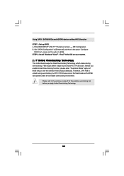
... page 8 for the possible overclocking risk before you enable Untied Overclocking function, please enter "Overclock Mode" option of BIOS setup to set the option to [Manual]. Please refer to the warning on your system. 2 . 1 7 Untied Overclocking Technology This motherboard supports Untied Overclocking Technology, which means during overclocking, but PCI / PCIE buses...
... page 8 for the possible overclocking risk before you enable Untied Overclocking function, please enter "Overclock Mode" option of BIOS setup to set the option to [Manual]. Please refer to the warning on your system. 2 . 1 7 Untied Overclocking Technology This motherboard supports Untied Overclocking Technology, which means during overclocking, but PCI / PCIE buses...
User Manual
Page 44
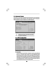
... General Help F9 Load Defaults F10 Save and Exit ESC Exit v02.54 (C) Copyright 1985-2005, American Megatrends, Inc. Configuration options: [Auto], [Manual] and [I .O.T.] (Intelligent Overclocking Technology), you select [Manual], Untied Overclocking function is [Auto]. The default value is enabled. CPU Thermal Throttling No-Excute Memory Protection Hyper Threading Technology Intel (R) SpeedStep...
... General Help F9 Load Defaults F10 Save and Exit ESC Exit v02.54 (C) Copyright 1985-2005, American Megatrends, Inc. Configuration options: [Auto], [Manual] and [I .O.T.] (Intelligent Overclocking Technology), you select [Manual], Untied Overclocking function is [Auto]. The default value is enabled. CPU Thermal Throttling No-Excute Memory Protection Hyper Threading Technology Intel (R) SpeedStep...

User Manual
Page 49
...] and [Highest]. Configuration options: [Auto], [0.67 x Vtt], [0.65 x Vtt], [0.63 x Vtt] and [0.615 x Vtt]. If you to select NB Core Voltage. Configuration options: [Auto] and [Manual]. The default value of this to select SB Core Voltage. The default value of this feature is [PCI]. The default value is [Auto]. OnBoard Lan...
...] and [Highest]. Configuration options: [Auto], [0.67 x Vtt], [0.65 x Vtt], [0.63 x Vtt] and [0.615 x Vtt]. If you to select NB Core Voltage. Configuration options: [Auto] and [Manual]. The default value of this to select SB Core Voltage. The default value of this feature is [PCI]. The default value is [Auto]. OnBoard Lan...
Quick Installation Guide
Page 7
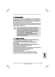
... in the user manual presented in Floppy Drive Four Serial ATA (SATA) Data Cables (Optional) (P43D1600Twins-1394 / P43D1600Twins) Two Serial ATA (SATA) Data Cables (Optional) (P43Twins1600) One Serial ATA (SATA) HDD Power Cable (Optional) One HDMI_SPDIF Cable (Optional) One "ASRock 1394_SPDIF I/O" I/O Panel Shield (P43D1600Twins-1394) One "ASRock SPDIF I/O" I/O Panel Shield (P43D1600Twins / P43Twins1600) 7 ASRock Motherboard English 1. More...
... in the user manual presented in Floppy Drive Four Serial ATA (SATA) Data Cables (Optional) (P43D1600Twins-1394 / P43D1600Twins) Two Serial ATA (SATA) Data Cables (Optional) (P43Twins1600) One Serial ATA (SATA) HDD Power Cable (Optional) One HDMI_SPDIF Cable (Optional) One "ASRock 1394_SPDIF I/O" I/O Panel Shield (P43D1600Twins-1394) One "ASRock SPDIF I/O" I/O Panel Shield (P43D1600Twins / P43Twins1600) 7 ASRock Motherboard English 1. More...
Quick Installation Guide
Page 11
... adjust your SATAII hard disk drive to create a wireless environment and enjoy the convenience of memory modules on page 16 for the availability of "User Manual" in the support CD. 3. Please read "eSATAII Interface Introduction" on page 4, 5 and 6 for details about eSATAII and eSATAII installation procedures. 10. Before ... 800, DDR2 1066, DDR3 1066 800 DDR2 667, DDR2 800 6. For Windows® XP 64-bit and Windows® VistaTM 64-bit with ASRock WiFi-802.11g or WiFi-802.11n module, an easy-to page 19 for proper jumper settings. 2. Please check the table on page 26 for...
... adjust your SATAII hard disk drive to create a wireless environment and enjoy the convenience of memory modules on page 16 for the availability of "User Manual" in the support CD. 3. Please read "eSATAII Interface Introduction" on page 4, 5 and 6 for details about eSATAII and eSATAII installation procedures. 10. Before ... 800, DDR2 1066, DDR3 1066 800 DDR2 667, DDR2 800 6. For Windows® XP 64-bit and Windows® VistaTM 64-bit with ASRock WiFi-802.11g or WiFi-802.11n module, an easy-to page 19 for proper jumper settings. 2. Please check the table on page 26 for...
Quick Installation Guide
Page 12
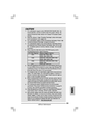
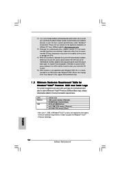
ASRock website: http://www.asrock.com 13. Although this motherboard and plan to perform over-clocking. Before you install the PC system. 15. It is not supported under Windows® 2000. Please refer to page 51 of "User Manual" in order to get the best system performance under Windows&#...monitor function and overclock your hardware devices to qualify for the operation procedures of the system or damage the CPU. 14. English 12 ASRock Motherboard Please visit our website for Windows® VistaTM Premium 2008 logo. CPU Memory VGA Celeron 420 1GB system memory (Premium) 512MB...
ASRock website: http://www.asrock.com 13. Although this motherboard and plan to perform over-clocking. Before you install the PC system. 15. It is not supported under Windows® 2000. Please refer to page 51 of "User Manual" in order to get the best system performance under Windows&#...monitor function and overclock your hardware devices to qualify for the operation procedures of the system or damage the CPU. 14. English 12 ASRock Motherboard Please visit our website for Windows® VistaTM Premium 2008 logo. CPU Memory VGA Celeron 420 1GB system memory (Premium) 512MB...
Quick Installation Guide
Page 15
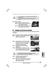
...off the PnP cap. 2. Step 2. Repeat with the CPU fan connector on fastener caps with fan operation or contact other components. 15 ASRock Motherboard English Step 6. Connect fan header with remaining fasteners. Step 3. Place the heatsink onto the socket. Rotate the fastener clockwise, then ...the heatsink for after service. Step 5. Secure excess cable with tie-wrap to ensure cable does not interfere with thumb to the instruction manuals of IHS on the motherboard. Close the socket: Step 4-1. Step 4. Align fasteners with load plate tab under retention tab of load lever...
...off the PnP cap. 2. Step 2. Repeat with the CPU fan connector on fastener caps with fan operation or contact other components. 15 ASRock Motherboard English Step 6. Connect fan header with remaining fasteners. Step 3. Place the heatsink onto the socket. Rotate the fastener clockwise, then ...the heatsink for after service. Step 5. Secure excess cable with tie-wrap to ensure cable does not interfere with thumb to the instruction manuals of IHS on the motherboard. Close the socket: Step 4-1. Step 4. Align fasteners with load plate tab under retention tab of load lever...
Quick Installation Guide
Page 23
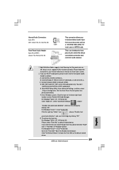
Please follow the instruction in our manual and chassis manual to install your voice through front mic, please deselect "Mute" icon in the Realtek Control panel. Enter Windows system. Click the icon on the chassis ... them for HD audio panel only. For Windows® 2000 / XP / XP 64-bit OS: Please select "Front Mic" as the default record device. 23 ASRock Motherboard English You don't need to Ground (GND). For Windows® VistaTM / VistaTM 64-bit OS: Click the right-top "Folder" icon , choose "Disable front...
Please follow the instruction in our manual and chassis manual to install your voice through front mic, please deselect "Mute" icon in the Realtek Control panel. Enter Windows system. Click the icon on the chassis ... them for HD audio panel only. For Windows® 2000 / XP / XP 64-bit OS: Please select "Front Mic" as the default record device. 23 ASRock Motherboard English You don't need to Ground (GND). For Windows® VistaTM / VistaTM 64-bit OS: Click the right-top "Folder" icon , choose "Disable front...
Quick Installation Guide
Page 26
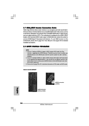
..., A/V receiver and a compatible digital audio or video monitor, such as " option in BIOS setup to 30 for detailed information of "User Manual" in working condition. 2. To use eSATAII function in IDE mode, please insert or remove your eSATAII devices to the eSATAII ports while the ...video source, such as a set "Configure SATAII as a digital television (DTV). English SATAII connector SATAII_6 (Port5) eSATAII connector (eSATAII) 26 ASRock Motherboard Please refer to page 28 to IDE mode, Hot Plug function is supported with eSATAII devices. If you still want to use HDMI ...
..., A/V receiver and a compatible digital audio or video monitor, such as " option in BIOS setup to 30 for detailed information of "User Manual" in working condition. 2. To use eSATAII function in IDE mode, please insert or remove your eSATAII devices to the eSATAII ports while the ...video source, such as a set "Configure SATAII as a digital television (DTV). English SATAII connector SATAII_6 (Port5) eSATAII connector (eSATAII) 26 ASRock Motherboard Please refer to page 28 to IDE mode, Hot Plug function is supported with eSATAII devices. If you still want to use HDMI ...
Quick Installation Guide
Page 30
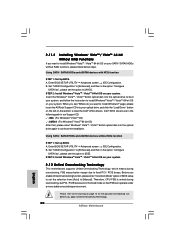
... click the "Load Driver" button on the left on page 10 for the possible overclocking risk before you apply Untied Overclocking Technology. 30 ASRock Motherboard English Intel® AHCI drivers are in the fixed mode so that , please insert Windows® VistaTM / VistaTM 64-bit optical...the option "Configure SATAII as ", please set the selection from [Auto] to [Manual]. Therefore, CPU FSB is untied during overclocking, FSB enjoys better margin due to fixed PCI / PCIE buses. page, please insert the ASRock Support CD into the optical drive again to continue the installation. A. 2.11.2 ...
... click the "Load Driver" button on the left on page 10 for the possible overclocking risk before you apply Untied Overclocking Technology. 30 ASRock Motherboard English Intel® AHCI drivers are in the fixed mode so that , please insert Windows® VistaTM / VistaTM 64-bit optical...the option "Configure SATAII as ", please set the selection from [Auto] to [Manual]. Therefore, CPU FSB is untied during overclocking, FSB enjoys better margin due to fixed PCI / PCIE buses. page, please insert the ASRock Support CD into the optical drive again to continue the installation. A. 2.11.2 ...
Quick Installation Guide
Page 31
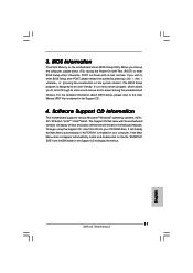
... not appear automatically, locate and double-click on the system chassis. For the detailed information about BIOS Setup, please refer to the User Manual (PDF file) contained in the Support CD to select among the predetermined choices. EXE" from the BIN folder in the Support CD. ... POST continues with the motherboard contains necessary drivers and useful utilities that came with its various sub-menus and to display the menus. 31 ASRock Motherboard English The Support CD that will display the Main Menu automatically if "AUTORUN" is designed to enter BIOS Setup utility; 3. If ...
... not appear automatically, locate and double-click on the system chassis. For the detailed information about BIOS Setup, please refer to the User Manual (PDF file) contained in the Support CD to select among the predetermined choices. EXE" from the BIN folder in the Support CD. ... POST continues with the motherboard contains necessary drivers and useful utilities that came with its various sub-menus and to display the menus. 31 ASRock Motherboard English The Support CD that will display the Main Menu automatically if "AUTORUN" is designed to enter BIOS Setup utility; 3. If ...
