User Manual
Page 9
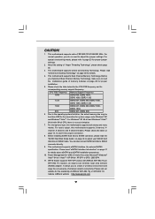
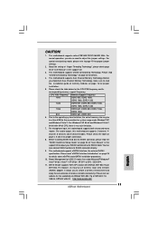
... adjust your SATAII hard disk drive to page 23 for USB 2.0 works fine under Windows® XP and Windows® VistaTM. This motherboard supports native FSB1600/1333/1066/800 MHz. You can also connect SATA hard disk to -use wireless local area network (WLAN) adapter. CAUTION! 1. About the setting of memory modules on page 20 for the availability of wireless network connectivity. This motherboard supports Untied Overclocking Technology. This motherboard supports Dual Channel Memory Technology. CPU FSB Frequency Memory Support Frequency 1600 DDR2 800...
... adjust your SATAII hard disk drive to page 23 for USB 2.0 works fine under Windows® XP and Windows® VistaTM. This motherboard supports native FSB1600/1333/1066/800 MHz. You can also connect SATA hard disk to -use wireless local area network (WLAN) adapter. CAUTION! 1. About the setting of memory modules on page 20 for the availability of wireless network connectivity. This motherboard supports Untied Overclocking Technology. This motherboard supports Dual Channel Memory Technology. CPU FSB Frequency Memory Support Frequency 1600 DDR2 800...
User Manual
Page 12
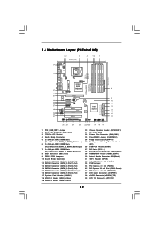
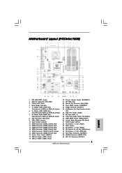
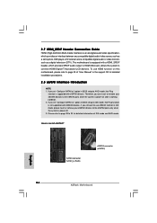
... USB 2.0 Header (USB6_7, Blue) 20 Chassis Speaker Header (SPEAKER 1) 21 SPI BIOS Chip 22 Chassis Fan Connector (CHA_FAN1) 23 Clear CMOS Jumper (CLRCMOS1) 24 Floppy Connector (FLOPPY1) 25 DeskExpress Hot Plug Detection Header (IR1) 26 COM Port Header (COM1) 27 PCI Slots (PCI1 - 3) 28 Front Panel Audio Header (HD_AUDIO1) 29 HDMI_SPDIF Header (HDMI_SPDIF1) 30 Internal Audio Connector: CD1 (Black) 31 WiFi/E Header (WIFI/E) 32 PCI Express x1 Slot (PCIE4) 33 FSB1 Jumper 34 PCI Express x1 Slot (PCIE3) 35 PCI Express 2.0 x16 Slot (PCIE2, Green) 36 PCI Express x1 Slot (PCIE1/DE) 37 ATX Power Connector...
... USB 2.0 Header (USB6_7, Blue) 20 Chassis Speaker Header (SPEAKER 1) 21 SPI BIOS Chip 22 Chassis Fan Connector (CHA_FAN1) 23 Clear CMOS Jumper (CLRCMOS1) 24 Floppy Connector (FLOPPY1) 25 DeskExpress Hot Plug Detection Header (IR1) 26 COM Port Header (COM1) 27 PCI Slots (PCI1 - 3) 28 Front Panel Audio Header (HD_AUDIO1) 29 HDMI_SPDIF Header (HDMI_SPDIF1) 30 Internal Audio Connector: CD1 (Black) 31 WiFi/E Header (WIFI/E) 32 PCI Express x1 Slot (PCIE4) 33 FSB1 Jumper 34 PCI Express x1 Slot (PCIE3) 35 PCI Express 2.0 x16 Slot (PCIE2, Green) 36 PCI Express x1 Slot (PCIE1/DE) 37 ATX Power Connector...
User Manual
Page 27
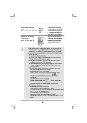
...-bit OS: Click "Audio I/O", select "Connector Settings" , choose "Disable front panel jack detection", and save the change by clicking "OK". Connect Audio_R (RIN) to OUT2_R and Audio_L (LIN) to install your voice through front mic, please deselect "Mute" icon in the Realtek Control panel. For Windows® 2000 / XP / XP 64-bit OS: Please select "Front Mic" as a CD-ROM, DVD-ROM, TV tuner card, or MPEG card. B. Internal Audio Connectors (4-pin...
...-bit OS: Click "Audio I/O", select "Connector Settings" , choose "Disable front panel jack detection", and save the change by clicking "OK". Connect Audio_R (RIN) to OUT2_R and Audio_L (LIN) to install your voice through front mic, please deselect "Mute" icon in the Realtek Control panel. For Windows® 2000 / XP / XP 64-bit OS: Please select "Front Mic" as a CD-ROM, DVD-ROM, TV tuner card, or MPEG card. B. Internal Audio Connectors (4-pin...
User Manual
Page 30
... user manual of HDMI VGA card. (There are two white ends (2-pin and 3-pin) on page 22. Please refer to the installation guide on HDMI_SPDIF cable. A complete HDMI system requires a HDMI VGA card and a HDMI ready motherboard with a HDMI_SPDIF header, which provides an interface between any compatible digital audio/ video source, such as a set-top box, DVD player, A/V receiver and a compatible digital audio or video monitor, such as HDTV. This motherboard is an all-digital audio/video specification, which provides SPDIF audio...
... user manual of HDMI VGA card. (There are two white ends (2-pin and 3-pin) on page 22. Please refer to the installation guide on HDMI_SPDIF cable. A complete HDMI system requires a HDMI VGA card and a HDMI ready motherboard with a HDMI_SPDIF header, which provides an interface between any compatible digital audio/ video source, such as a set-top box, DVD player, A/V receiver and a compatible digital audio or video monitor, such as HDTV. This motherboard is an all-digital audio/video specification, which provides SPDIF audio...
User Manual
Page 31
... to use eSATAII function in BIOS setup to 42 for external interface. Therefore, you to 3.0Gb/s, and the convenient mobility like USB. eSATAII is supported with Hot Plug capability that enables you can insert or remove your computer, offering the high speed data transfer rate up to exchange drives easily. If you set "Configure SATAII as " option in IDE mode, please insert or remove your SATAII hard disk. How...
... to use eSATAII function in BIOS setup to 42 for external interface. Therefore, you to 3.0Gb/s, and the convenient mobility like USB. eSATAII is supported with Hot Plug capability that enables you can insert or remove your computer, offering the high speed data transfer rate up to exchange drives easily. If you set "Configure SATAII as " option in IDE mode, please insert or remove your SATAII hard disk. How...
User Manual
Page 38
...-bit Without RAID Functions If you want to generate Serial ATA driver diskette [YN]?", press . WARNING! B. STEP 2: Make a SATA / SATAII driver diskette. D. The system will lose ALL data in the option "Configure SATAII as the boot device. C. E. Enter BIOS SETUP UTILITY Advanced screen IDE Configuration. Formatting the floppy diskette will start to format the floppy diskette and copy SATA / SATAII drivers into the floppy drive, and press . A. Then, the drivers compatible to your system. A. 2.15 Driver Installation Guide To install...
...-bit Without RAID Functions If you want to generate Serial ATA driver diskette [YN]?", press . WARNING! B. STEP 2: Make a SATA / SATAII driver diskette. D. The system will lose ALL data in the option "Configure SATAII as the boot device. C. E. Enter BIOS SETUP UTILITY Advanced screen IDE Configuration. Formatting the floppy diskette will start to format the floppy diskette and copy SATA / SATAII drivers into the floppy drive, and press . A. Then, the drivers compatible to your system. A. 2.15 Driver Installation Guide To install...
User Manual
Page 44
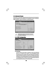
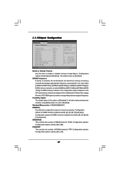
... section, you may set the configurations for the details of Untied Overclocking Technology. CPU Configuration Chipset Configuration ACPI Configuration IDE Configuration PCIPnP Configuration Floppy Configuration SuperIO Configuration USB Configuration Configure CPU Select Screen Select Item Enter Go to malfunction. 3.3.1CPU Configuration BIOS SETUP UTILITY Advanced CPU Configuration Overclock Mode CPU Frequency (MHz) PCIE Frequency (MHz) Boot Failure Guard Spread Spectrum [Auto] [266] [100] [Enabled] [Auto] Ratio Status Ratio Actual Value Unlocked (Min: 06, Max: 08) 8 Enhanced Halt...
... section, you may set the configurations for the details of Untied Overclocking Technology. CPU Configuration Chipset Configuration ACPI Configuration IDE Configuration PCIPnP Configuration Floppy Configuration SuperIO Configuration USB Configuration Configure CPU Select Screen Select Item Enter Go to malfunction. 3.3.1CPU Configuration BIOS SETUP UTILITY Advanced CPU Configuration Overclock Mode CPU Frequency (MHz) PCIE Frequency (MHz) Boot Failure Guard Spread Spectrum [Auto] [266] [100] [Enabled] [Auto] Ratio Status Ratio Actual Value Unlocked (Min: 06, Max: 08) 8 Enhanced Halt...
User Manual
Page 47
... item to [Enabled]. Configuration options for DDR2 memory modules are [5], [6], [7], [8], [9], [10] and [Auto]. The default value is selected, the motherboard will allow remapping of memory accessing. DRAM tRAS This controls the number of overlapped PCI memory above the total physical memory. Memory Remap Feature Use this motherboard. DRAM Frequency If [Auto] is [Disabled]. 3.3.2Chipset Configuration BIOS SETUP UTILITY Advanced Chipset Configuration Memory Remap Feature [Disabled] DRAM Frequency [Auto] Flexibility Option [Disabled] Standard Memory Info : 4-15...
... item to [Enabled]. Configuration options for DDR2 memory modules are [5], [6], [7], [8], [9], [10] and [Auto]. The default value is selected, the motherboard will allow remapping of memory accessing. DRAM tRAS This controls the number of overlapped PCI memory above the total physical memory. Memory Remap Feature Use this motherboard. DRAM Frequency If [Auto] is [Disabled]. 3.3.2Chipset Configuration BIOS SETUP UTILITY Advanced Chipset Configuration Memory Remap Feature [Disabled] DRAM Frequency [Auto] Flexibility Option [Disabled] Standard Memory Info : 4-15...
User Manual
Page 51
... motherboard to submit Windows® VistaTM certification. 3.3.4IDE Configuration BIOS SETUP UTILITY Advanced IDE Configuration SATAII Configuration Configure SATAII as Hot Plug OnBoard IDE Controller [Enhanced] [AHCI] [Enabled] [Enabled] Options Disabled Compatible Enhanced SATAII 1 SATAII 2 SATAII 3 SATAII 4 SATAII 5 SATAII 6 IDE1 Master IDE1 Slave AHCI CD/DVD Boot Time out [Hard Disk] [Not Detected] [Not Detected] [Not Detected] [Not Detected] [Not Detected] [Not Detected] [Not Detected] [20] +F1 F9 F10 ESC Select Screen Select Item Change Option General Help Load Defaults...
... motherboard to submit Windows® VistaTM certification. 3.3.4IDE Configuration BIOS SETUP UTILITY Advanced IDE Configuration SATAII Configuration Configure SATAII as Hot Plug OnBoard IDE Controller [Enhanced] [AHCI] [Enabled] [Enabled] Options Disabled Compatible Enhanced SATAII 1 SATAII 2 SATAII 3 SATAII 4 SATAII 5 SATAII 6 IDE1 Master IDE1 Slave AHCI CD/DVD Boot Time out [Hard Disk] [Not Detected] [Not Detected] [Not Detected] [Not Detected] [Not Detected] [Not Detected] [Not Detected] [20] +F1 F9 F10 ESC Select Screen Select Item Change Option General Help Load Defaults...
User Manual
Page 52
... new IDE hard disk drives. BIOS SETUP UTILITY Advanced Primary IDE Master Device Vendor Size LBA Mode Block Mode PIO Mode Async DMA Ultra DMA S.M.A.R.T. Configuration options: [Not Installed], [Auto], [CD/DVD], and [ARMD]. [Not Installed]: Select [Not Installed] to disable the use of the Primary IDE hard disk drives to enable or disable onboard IDE controller. Type LBA/Large Mode Block (Multi-Sector Transfer) PIO Mode DMA Mode S.M.A.R.T. 32Bit Data Transfer :Hard Disk :ST340014A :40.0 GB :Supported :16Sectors :4 :MultiWord DMA-2 :Ultra DMA-5 :Supported [Auto] [Auto] [Auto] [Auto...
... new IDE hard disk drives. BIOS SETUP UTILITY Advanced Primary IDE Master Device Vendor Size LBA Mode Block Mode PIO Mode Async DMA Ultra DMA S.M.A.R.T. Configuration options: [Not Installed], [Auto], [CD/DVD], and [ARMD]. [Not Installed]: Select [Not Installed] to disable the use of the Primary IDE hard disk drives to enable or disable onboard IDE controller. Type LBA/Large Mode Block (Multi-Sector Transfer) PIO Mode DMA Mode S.M.A.R.T. 32Bit Data Transfer :Hard Disk :ST340014A :40.0 GB :Supported :16Sectors :4 :MultiWord DMA-2 :Ultra DMA-5 :Supported [Auto] [Auto] [Auto] [Auto...
User Manual
Page 53
.... Configuration options: [Disabled], [Auto], [Enabled]. 32-Bit Data Transfer Use this item to maximize the IDE hard disk data transfer rate. 53 Use this item to enable 32-bit access to enable or disable the S.M.A.R.T. (Self-Monitoring, Analysis, and Reporting Technology) feature. S.M.A.R.T. for compatible IDE devices. Block (Multi-Sector Transfer) The default value of this feature is used for IDE ARMD (ATAPI Removable Media Device), such as MO. [CD/DVD]: This is used for IDE CD/DVD drives. [ARMD]: This is enabled...
.... Configuration options: [Disabled], [Auto], [Enabled]. 32-Bit Data Transfer Use this item to maximize the IDE hard disk data transfer rate. 53 Use this item to enable 32-bit access to enable or disable the S.M.A.R.T. (Self-Monitoring, Analysis, and Reporting Technology) feature. S.M.A.R.T. for compatible IDE devices. Block (Multi-Sector Transfer) The default value of this feature is used for IDE ARMD (ATAPI Removable Media Device), such as MO. [CD/DVD]: This is used for IDE CD/DVD drives. [ARMD]: This is enabled...
User Manual
Page 56
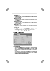
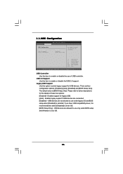
... details of USB controller. Please refer to use under BIOS setup and Windows / Linux OS. 56 USB Controller Use this item to use only under legacy OS and BIOS setup when [Disabled] is selected. USB devices are not allowed to enable or disable the USB 2.0 support. 3.3.8USB Configuration BIOS SETUP UTILITY Advanced USB Configuration USB Controller USB 2.0 Support Legacy USB Support [Enabled] [Enabled] [BIOS Setup Only] To enable or disable the onboard USB controllers. +F1 F9 F10 ESC Select Screen Select Item Change Option General Help Load Defaults Save and Exit...
... details of USB controller. Please refer to use under BIOS setup and Windows / Linux OS. 56 USB Controller Use this item to use only under legacy OS and BIOS setup when [Disabled] is selected. USB devices are not allowed to enable or disable the USB 2.0 support. 3.3.8USB Configuration BIOS SETUP UTILITY Advanced USB Configuration USB Controller USB 2.0 Support Legacy USB Support [Enabled] [Enabled] [BIOS Setup Only] To enable or disable the onboard USB controllers. +F1 F9 F10 ESC Select Screen Select Item Change Option General Help Load Defaults Save and Exit...
User Manual
Page 59
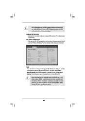
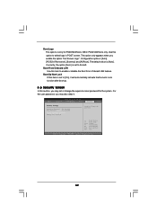
... . BIOS SETUP UTILITY Main Advanced H/W Monitor Boot Security Exit Security Settings Supervisor Password : Not Installed User Password : Not Installed Change Supervisor Password Change User Password Install or Change the password. Select Screen Select Item Enter Change F1 General Help F9 Load Defaults F10 Save and Exit ESC Exit v02.54 (C) Copyright 1985-2005, American Megatrends, Inc. 59 Configuration options: [Auto], [PCIE2.0 Revolution], [Scenery] and [ASRock]. Boot Up Num-Lock If this section, you enable the option "Full Screen Logo". Currently, the option [Auto] is...
... . BIOS SETUP UTILITY Main Advanced H/W Monitor Boot Security Exit Security Settings Supervisor Password : Not Installed User Password : Not Installed Change Supervisor Password Change User Password Install or Change the password. Select Screen Select Item Enter Change F1 General Help F9 Load Defaults F10 Save and Exit ESC Exit v02.54 (C) Copyright 1985-2005, American Megatrends, Inc. 59 Configuration options: [Auto], [PCIE2.0 Revolution], [Scenery] and [ASRock]. Boot Up Num-Lock If this section, you enable the option "Full Screen Logo". Currently, the option [Auto] is...
User Manual
Page 61
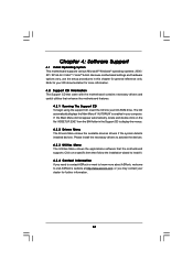
... CD-ROM drive. If the Main Menu did not appear automatically, locate and double click on a specific item then follow the installation wizard to activate the devices. 4.2.3 Utilities Menu The Utilities Menu shows the applications software that enhance the motherboard features. 4.2.1 Running The Support CD To begin using the support CD, insert the CD into your dealer for general reference only. Because motherboard settings and hardware options vary, use the setup procedures...
... CD-ROM drive. If the Main Menu did not appear automatically, locate and double click on a specific item then follow the installation wizard to activate the devices. 4.2.3 Utilities Menu The Utilities Menu shows the applications software that enhance the motherboard features. 4.2.1 Running The Support CD To begin using the support CD, insert the CD into your dealer for general reference only. Because motherboard settings and hardware options vary, use the setup procedures...
Quick Installation Guide
Page 3
... USB 2.0 Header (USB6_7, Blue) 20 Chassis Speaker Header (SPEAKER 1) 21 SPI BIOS Chip 22 Chassis Fan Connector (CHA_FAN1) 23 Clear CMOS Jumper (CLRCMOS1) 24 Floppy Connector (FLOPPY1) 25 DeskExpress Hot Plug Detection Header (IR1) 26 COM Port Header (COM1) 27 PCI Slots (PCI1 - 3) 28 Front Panel Audio Header (HD_AUDIO1) 29 HDMI_SPDIF Header (HDMI_SPDIF1) 30 Internal Audio Connector: CD1 (Black) 31 WiFi/E Header (WIFI/E) 32 PCI Express x1 Slot (PCIE4) 33 FSB1 Jumper 34 PCI Express x1 Slot (PCIE3) 35 PCI Express 2.0 x16 Slot (PCIE2, Green) 36 PCI Express x1 Slot (PCIE1/DE) 37 ATX Power Connector...
... USB 2.0 Header (USB6_7, Blue) 20 Chassis Speaker Header (SPEAKER 1) 21 SPI BIOS Chip 22 Chassis Fan Connector (CHA_FAN1) 23 Clear CMOS Jumper (CLRCMOS1) 24 Floppy Connector (FLOPPY1) 25 DeskExpress Hot Plug Detection Header (IR1) 26 COM Port Header (COM1) 27 PCI Slots (PCI1 - 3) 28 Front Panel Audio Header (HD_AUDIO1) 29 HDMI_SPDIF Header (HDMI_SPDIF1) 30 Internal Audio Connector: CD1 (Black) 31 WiFi/E Header (WIFI/E) 32 PCI Express x1 Slot (PCIE4) 33 FSB1 Jumper 34 PCI Express x1 Slot (PCIE3) 35 PCI Express 2.0 x16 Slot (PCIE2, Green) 36 PCI Express x1 Slot (PCIE1/DE) 37 ATX Power Connector...
Quick Installation Guide
Page 11
...-to adjust the jumper settings. This motherboard supports eSATAII interface, the external SATAII specification. It allows you do no such limitation. 7. channel, 6-channel, and 8-channel modes. WiFi/E header supports WiFi+AP function with 64-bit CPU, there is no need to -use wireless local area network (WLAN) adapter. Please read the installation guide of wireless network connectivity. For normal operation, you to SATAII connector directly. 9. This motherboard supports Untied Overclocking Technology. Please check the...
...-to adjust the jumper settings. This motherboard supports eSATAII interface, the external SATAII specification. It allows you do no such limitation. 7. channel, 6-channel, and 8-channel modes. WiFi/E header supports WiFi+AP function with 64-bit CPU, there is no need to -use wireless local area network (WLAN) adapter. Please read the installation guide of wireless network connectivity. For normal operation, you to SATAII connector directly. 9. This motherboard supports Untied Overclocking Technology. Please check the...
Quick Installation Guide
Page 26
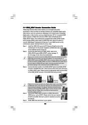
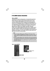
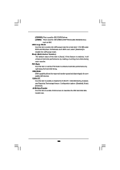
... for detailed installation procedures. 2.8 eSATAII Interface Introduction NOTE: 1. 2.7 HDMI_SPDIF Header Connection Guide HDMI (High-Definition Multi-media Interface) is supported with eSATAII devices. To use eSATAII function in BIOS setup to install eSATAII? If you set -top box, DVD player, A/V receiver and a compatible digital audio or video monitor, such as " option in IDE mode, please insert or remove your eSATAII devices to connect HDMI Digital TV/projector/LCD devices. English SATAII connector SATAII_6 (Port5) eSATAII connector (eSATAII) 26 ASRock Motherboard
... for detailed installation procedures. 2.8 eSATAII Interface Introduction NOTE: 1. 2.7 HDMI_SPDIF Header Connection Guide HDMI (High-Definition Multi-media Interface) is supported with eSATAII devices. To use eSATAII function in BIOS setup to install eSATAII? If you set -top box, DVD player, A/V receiver and a compatible digital audio or video monitor, such as " option in IDE mode, please insert or remove your eSATAII devices to connect HDMI Digital TV/projector/LCD devices. English SATAII connector SATAII_6 (Port5) eSATAII connector (eSATAII) 26 ASRock Motherboard
Quick Installation Guide
Page 28
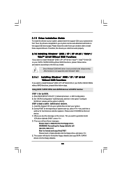
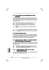
... hard disk. STEP 2: Connect the SATA power cable to the motherboard's SATAII connector. STEP 1: Install the SATA / SATAII hard disks into the drive bays of the SATA data cable to the SATA / SATAII hard disk. It is not supported under Windows® 2000. 2.11.1 Installing Windows® 2000 / XP / XP 64-bit Without RAID Functions If you want to install Windows® 2000 / XP / XP 64-bit / VistaTM / VistaTM 64-bit OS on this motherboard for internal storage devices. 2 . 9 Serial ATA (SATA) / Serial ATAII (SATAII) Hard Disks Installation...
... hard disk. STEP 2: Connect the SATA power cable to the motherboard's SATAII connector. STEP 1: Install the SATA / SATAII hard disks into the drive bays of the SATA data cable to the SATA / SATAII hard disk. It is not supported under Windows® 2000. 2.11.1 Installing Windows® 2000 / XP / XP 64-bit Without RAID Functions If you want to install Windows® 2000 / XP / XP 64-bit / VistaTM / VistaTM 64-bit OS on this motherboard for internal storage devices. 2 . 9 Serial ATA (SATA) / Serial ATAII (SATAII) Hard Disks Installation...
Quick Installation Guide
Page 30
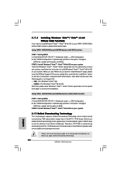
.... Enter BIOS SETUP UTILITY Advanced screen IDE Configuration. Insert the Windows® VistaTM / VistaTM 64-bit optical disk into your system. 2.12 Untied Overclocking Technology This motherboard supports Untied Overclocking Technology, which means during overclocking, but PCI / PCIE buses are in the following path in the option "Configure SATAII as ", please set the selection from [Auto] to install Windows® VistaTM / VistaTM 64-bit OS on your SATA / SATAII HDDs without NCQ function STEP 1: Set up BIOS. Using SATA / SATAII HDDs and eSATAII devices...
.... Enter BIOS SETUP UTILITY Advanced screen IDE Configuration. Insert the Windows® VistaTM / VistaTM 64-bit optical disk into your system. 2.12 Untied Overclocking Technology This motherboard supports Untied Overclocking Technology, which means during overclocking, but PCI / PCIE buses are in the following path in the option "Configure SATAII as ", please set the selection from [Auto] to install Windows® VistaTM / VistaTM 64-bit OS on your SATA / SATAII HDDs without NCQ function STEP 1: Set up BIOS. Using SATA / SATAII HDDs and eSATAII devices...
Quick Installation Guide
Page 31
... motherboard stores BIOS Setup Utility. EXE" from the BIN folder in your CD-ROM drive. Software Support CD information This motherboard supports various Microsoft® Windows® operating systems: 2000 / XP / XP 64-bit / VistaTM / VistaTM 64-bit. It will enhance motherboard features. BIOS Information The Flash Memory on the file "ASSETUP. When you wish to enter BIOS Setup utility; It is designed to the User Manual (PDF file) contained in the Support CD. 4. To begin using the Support...
... motherboard stores BIOS Setup Utility. EXE" from the BIN folder in your CD-ROM drive. Software Support CD information This motherboard supports various Microsoft® Windows® operating systems: 2000 / XP / XP 64-bit / VistaTM / VistaTM 64-bit. It will enhance motherboard features. BIOS Information The Flash Memory on the file "ASSETUP. When you wish to enter BIOS Setup utility; It is designed to the User Manual (PDF file) contained in the Support CD. 4. To begin using the Support...


