User Manual
Page 2
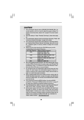
... to infringe. CALIFORNIA, USA ONLY The Lithium battery adopted on this motherboard contains Perchlorate, a toxic substance controlled in this manual may or may cause undesired operation. ASRock assumes no event shall ASRock, its directors, officers, employees, or agents be constructed as a ...the related regulations in this device must accept any errors or omissions that may not be registered trademarks or copyrights of ASRock Inc. Disclaimer: Specifications and information contained in advance. In no responsibility for identification or explanation and to the owners...
... to infringe. CALIFORNIA, USA ONLY The Lithium battery adopted on this motherboard contains Perchlorate, a toxic substance controlled in this manual may or may cause undesired operation. ASRock assumes no event shall ASRock, its directors, officers, employees, or agents be constructed as a ...the related regulations in this device must accept any errors or omissions that may not be registered trademarks or copyrights of ASRock Inc. Disclaimer: Specifications and information contained in advance. In no responsibility for identification or explanation and to the owners...
User Manual
Page 3
... 5 1.1 Package Contents 5 1.2 Specifications 6 1.3 Minimum Hardware Requirement Table for Windows® VistaTM Premium 2008 and Basic Logo 10 1.4 Motherboard Layout (P43D1600Twins-1394 / P43D1600Twins 11 1.5 Motherboard Layout (P43Twins1600 12 1.6 ASRock 1394_SPDIF I/O (P43D1600Twins-1394 13 1.7 ASRock SPDIF I/O (P43D1600Twins 14 1.8 ASRock SPDIF I/O (P43Twins1600 15 2 Installation 16 2.1 Screw Holes 16 2.2 Pre-installation Precautions 16 2.3 CPU Installation 17 2.4 Installation of Heatsink and CPU...
... 5 1.1 Package Contents 5 1.2 Specifications 6 1.3 Minimum Hardware Requirement Table for Windows® VistaTM Premium 2008 and Basic Logo 10 1.4 Motherboard Layout (P43D1600Twins-1394 / P43D1600Twins 11 1.5 Motherboard Layout (P43Twins1600 12 1.6 ASRock 1394_SPDIF I/O (P43D1600Twins-1394 13 1.7 ASRock SPDIF I/O (P43D1600Twins 14 1.8 ASRock SPDIF I/O (P43Twins1600 15 2 Installation 16 2.1 Screw Holes 16 2.2 Pre-installation Precautions 16 2.3 CPU Installation 17 2.4 Installation of Heatsink and CPU...
User Manual
Page 5
... CD One 80-conductor Ultra ATA 66/100/133 IDE Ribbon Cable One Ribbon Cable for purchasing ASRock P43D1600Twins-1394 / P43D1600Twins / P43Twins1600 motherboard, a reliable motherboard produced under ASRock's consistently stringent quality control. ASRock website http://www.asrock.com If you require technical support related to this manual occur, the updated version will be updated, the content of...
... CD One 80-conductor Ultra ATA 66/100/133 IDE Ribbon Cable One Ribbon Cable for purchasing ASRock P43D1600Twins-1394 / P43D1600Twins / P43Twins1600 motherboard, a reliable motherboard produced under ASRock's consistently stringent quality control. ASRock website http://www.asrock.com If you require technical support related to this manual occur, the updated version will be updated, the content of...
User Manual
Page 9
...DDR3 1066 800 DDR2 667, DDR2 800 6. channel, 6-channel, and 8-channel modes. This motherboard supports eSATAII interface, the external SATAII specification. ASRock website http://www.asrock.com 9 This motherboard supports Untied Overclocking Technology. For Windows® XP 64-bit and Windows® VistaTM 64-...bit CPU, there is no need to SATAII mode. This motherboard supports native FSB1600/1333/1066/800 MHz. About the setting of ASRock WiFi-802.11g or WiFi-802.11n module. This motherboard supports Dual Channel Memory Technology. Please check the table below...
...DDR3 1066 800 DDR2 667, DDR2 800 6. channel, 6-channel, and 8-channel modes. This motherboard supports eSATAII interface, the external SATAII specification. ASRock website http://www.asrock.com 9 This motherboard supports Untied Overclocking Technology. For Windows® XP 64-bit and Windows® VistaTM 64-...bit CPU, there is no need to SATAII mode. This motherboard supports native FSB1600/1333/1066/800 MHz. About the setting of ASRock WiFi-802.11g or WiFi-802.11n module. This motherboard supports Dual Channel Memory Technology. Please check the table below...
User Manual
Page 10
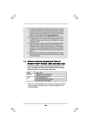
...supported under Windows® 2000. While CPU overheat is not recommended to use IDE mode under Windows® 2000 OS. Although this motherboard and plan to qualify for Windows® VistaTM Premium 2008 logo. 10 Please visit our website for minimum hardware requirements. Please refer ... and Basic Logo For system integrators and users who purchase this motherboard offers stepless control, it back again. Before you install the PC system. 15. It is recommended to perform over-clocking. ASRock website: http://www.asrock.com 13. CPU Memory VGA Celeron 420 1GB system memory (...
...supported under Windows® 2000. While CPU overheat is not recommended to use IDE mode under Windows® 2000 OS. Although this motherboard and plan to qualify for Windows® VistaTM Premium 2008 logo. 10 Please visit our website for minimum hardware requirements. Please refer ... and Basic Logo For system integrators and users who purchase this motherboard offers stepless control, it back again. Before you install the PC system. 15. It is recommended to perform over-clocking. ASRock website: http://www.asrock.com 13. CPU Memory VGA Celeron 420 1GB system memory (...
User Manual
Page 11
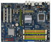
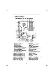
Orange) 7 2 x 240-pin DDR3 DIMM Slots (Dual Channel C: DDR3_A1, DDR3_B1; 1.4 Motherboard Layout (P43D1600Twins-1394 / P43D1600Twins) 12 3 4 56 7 24.4cm (9.6 in) PS2 Mouse PS2 Keyboard 40 1 PS2_USB_PWR1 Coaxial SPDIF Optical SPDIF 39 38 37 36 35 34 ...
Orange) 7 2 x 240-pin DDR3 DIMM Slots (Dual Channel C: DDR3_A1, DDR3_B1; 1.4 Motherboard Layout (P43D1600Twins-1394 / P43D1600Twins) 12 3 4 56 7 24.4cm (9.6 in) PS2 Mouse PS2 Keyboard 40 1 PS2_USB_PWR1 Coaxial SPDIF Optical SPDIF 39 38 37 36 35 34 ...
User Manual
Page 12
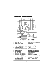
...240-pin DDR3 DIMM Slots (Dual Channel C: DDR3_A1, DDR3_B1; Yellow) 6 2 x 240-pin DDR2 DIMM Slots (Dual Channel B: DDRII_A2, DDRII_B2; 1.5 Motherboard Layout (P43Twins1600) 12 3 24.4cm (9.6 in) 4 56 7 PS2 Mouse PS2 Keyboard 39 1 PS2_USB_PWR1 Coaxial SPDIF Optical SPDIF 38 37 36 35 34 33 32 31... Top: SIDE SPK Center: REAR SPK Bottom: CTR BASS Top: LINE IN Center: FRONT Bottom: MIC IN LAN PCIE1/DE PHY Intel P43 Chipset P43Twins1600 Dual Channel Quad Core CPU Super I/O CD1 AUDIO CODEC 1 HDMI_SPDIF1 1 HD_AUDIO1 COM1 1 PCIE3 PCIE2 PCI Express 2.0 1 FSB3 1 FSB2 PCIE4 1 ...
...240-pin DDR3 DIMM Slots (Dual Channel C: DDR3_A1, DDR3_B1; Yellow) 6 2 x 240-pin DDR2 DIMM Slots (Dual Channel B: DDRII_A2, DDRII_B2; 1.5 Motherboard Layout (P43Twins1600) 12 3 24.4cm (9.6 in) 4 56 7 PS2 Mouse PS2 Keyboard 39 1 PS2_USB_PWR1 Coaxial SPDIF Optical SPDIF 38 37 36 35 34 33 32 31... Top: SIDE SPK Center: REAR SPK Bottom: CTR BASS Top: LINE IN Center: FRONT Bottom: MIC IN LAN PCIE1/DE PHY Intel P43 Chipset P43Twins1600 Dual Channel Quad Core CPU Super I/O CD1 AUDIO CODEC 1 HDMI_SPDIF1 1 HD_AUDIO1 COM1 1 PCIE3 PCIE2 PCI Express 2.0 1 FSB3 1 FSB2 PCIE4 1 ...
User Manual
Page 16
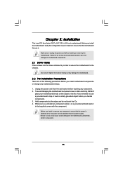
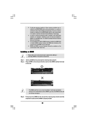
...the bag that the power is switched off or the power cord is an ATX form factor (12.0" x 9.6", 30.5 x 24.4 cm) motherboard. Do not over-tighten the screws! Failure to do so may cause physical injuries to you uninstall any component, ensure that comes with the ...to the chassis. Chapter 2: Installation This is detached from the wall socket before touching any motherboard settings. 1. Unplug the power cord from the power supply. Hold components by circles to secure the motherboard to use a grounded wrist strap or touch a safety grounded object before you install or remove...
...the bag that the power is switched off or the power cord is an ATX form factor (12.0" x 9.6", 30.5 x 24.4 cm) motherboard. Do not over-tighten the screws! Failure to do so may cause physical injuries to you uninstall any component, ensure that comes with the ...to the chassis. Chapter 2: Installation This is detached from the wall socket before touching any motherboard settings. 1. Unplug the power cord from the power supply. Hold components by circles to secure the motherboard to use a grounded wrist strap or touch a safety grounded object before you install or remove...
User Manual
Page 18
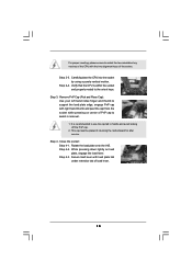
... load lever. Step 2-3. Step 3. Step 4. Carefully place the CPU into the socket by using a purely vertical motion. This cap must be placed if returning the motherboard for after service.
... load lever. Step 2-3. Step 3. Step 4. Carefully place the CPU into the socket by using a purely vertical motion. This cap must be placed if returning the motherboard for after service.
User Manual
Page 19
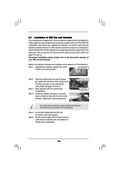
Ensure that supports Intel 775-LAND CPU. Step 2. Place the heatsink onto the socket. Repeat with the motherboard throughholes. 2.4 Installation of CPU Fan and Heatsink This motherboard is an example to illustrate the installation of the heatsink for 775-LAND CPU. Step 4. Step 5. For proper ... 1. Connect fan header with Intel 775-LAND CPU to improve heat dissipation. Before you installed the heatsink, you press down on the motherboard (CPU_FAN1, see page 11/12, No. 2). Please adopt the type of heatsink and cooling fan compliant with the CPU fan connector ...
Ensure that supports Intel 775-LAND CPU. Step 2. Place the heatsink onto the socket. Repeat with the motherboard throughholes. 2.4 Installation of CPU Fan and Heatsink This motherboard is an example to illustrate the installation of the heatsink for 775-LAND CPU. Step 4. Step 5. For proper ... 1. Connect fan header with Intel 775-LAND CPU to improve heat dissipation. Before you installed the heatsink, you press down on the motherboard (CPU_FAN1, see page 11/12, No. 2). Please adopt the type of heatsink and cooling fan compliant with the CPU fan connector ...
User Manual
Page 20
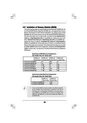
This motherboard also allows you always need to install identical (the same brand, speed, size and chip-type) DDR2/DDR3 DIMM pair in the slots of the ... Channel Memory Technology can be activated. Yellow slots; You may refer to install identical DDR2 DIMM pair in the set of Memory Modules (DIMM) This motherboard provides four 240-pin DDR2 (Double Data Rate 2) DIMM slots and two 240-pin DDR3 (Double Data Rate 3) DIMM slots, and supports Dual Channel Memory...
This motherboard also allows you always need to install identical (the same brand, speed, size and chip-type) DDR2/DDR3 DIMM pair in the slots of the ... Channel Memory Technology can be activated. Yellow slots; You may refer to install identical DDR2 DIMM pair in the set of Memory Modules (DIMM) This motherboard provides four 240-pin DDR2 (Double Data Rate 2) DIMM slots and two 240-pin DDR3 (Double Data Rate 3) DIMM slots, and supports Dual Channel Memory...
User Manual
Page 21
... of memory modules is NOT installed in the same Dual Channel, for example, installing a pair of memory modules in the DDR3 DIMM slots on this motherboard, it is unable to install a DDR3 memory module into DDR2 slot or install a DDR2 memory module into the slot until the retaining clips at the... same time. If only one memory module is installed in DDRII_A1 and DDRII_B2, it is unable to the motherboard and the DIMM if you force the DIMM into the slot at incorrect orientation. Step 1. notch break notch break The DIMM only fits in one...
... of memory modules is NOT installed in the same Dual Channel, for example, installing a pair of memory modules in the DDR3 DIMM slots on this motherboard, it is unable to install a DDR3 memory module into DDR2 slot or install a DDR2 memory module into the slot until the retaining clips at the... same time. If only one memory module is installed in DDRII_A1 and DDRII_B2, it is unable to the motherboard and the DIMM if you force the DIMM into the slot at incorrect orientation. Step 1. notch break notch break The DIMM only fits in one...
User Manual
Page 22
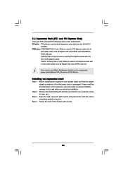
... card. If you want to install expansion cards that the power supply is switched off or the power cord is used to use ASRock DeskExpress function on this motherboard. Keep the screws for PCI Express cards with screws. 22 Green) is unplugged. Before installing the expansion card, please make necessary hardware settings... (PCIE x1 slot; White) is completely seated on PCIE1/DE slot. Step 3. PCI slots: PCI slots are 3 PCI slots and 4 PCI Express slots on this motherboard, please install ASRock PCIE_DE card on the slot. Fasten the card to use. PCIE2 (PCIE x16 slot;
... card. If you want to install expansion cards that the power supply is switched off or the power cord is used to use ASRock DeskExpress function on this motherboard. Keep the screws for PCI Express cards with screws. 22 Green) is unplugged. Before installing the expansion card, please make necessary hardware settings... (PCIE x1 slot; White) is completely seated on PCIE1/DE slot. Step 3. PCI slots: PCI slots are 3 PCI slots and 4 PCI Express slots on this motherboard, please install ASRock PCIE_DE card on the slot. Fasten the card to use. PCIE2 (PCIE x16 slot;
User Manual
Page 24
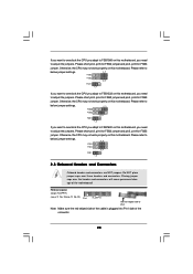
Please refer to below jumper settings. 4_5 FSB3 FSB2 3_4 FSB1 1_2 If you want to overclock the CPU you adopt to FSB1600 on this motherboard, you need to adjust the jumpers. Do NOT place jumper caps over the headers and connectors will cause permanent damage of the connector. 24 ... FSB2 3_4 FSB1 1_2 2.8 Onboard Headers and Connectors Onboard headers and connectors are NOT jumpers. Otherwise, the CPU may not work properly on this motherboard. Please refer to below jumper settings. 4_5 FSB3 FSB2 4_5 FSB1 1_2 If you want to overclock the CPU you adopt to FSB1066 on this...
Please refer to below jumper settings. 4_5 FSB3 FSB2 3_4 FSB1 1_2 If you want to overclock the CPU you adopt to FSB1600 on this motherboard, you need to adjust the jumpers. Do NOT place jumper caps over the headers and connectors will cause permanent damage of the connector. 24 ... FSB2 3_4 FSB1 1_2 2.8 Onboard Headers and Connectors Onboard headers and connectors are NOT jumpers. Otherwise, the CPU may not work properly on this motherboard. Please refer to below jumper settings. 4_5 FSB3 FSB2 4_5 FSB1 1_2 If you want to overclock the CPU you adopt to FSB1066 on this...
User Manual
Page 25
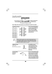
... SATA data cable for the details. Primary IDE connector (Blue) (39-pin IDE1, see p.11/12 No. 8) PIN1 IDE1 connect the blue end to the motherboard connect the black end to the IDE devices 80-conductor ATA 66/100/133 cable Note: Please refer to the instruction of the SATA data... SATAII_6 (Port5) connector and eSATAII connector. 25 The current SATAII interface allows up to 3.0 Gb/s data transfer rate. Please read "eSATAII Interface Introduction" on this motherboard. You can be used for internal storage devices.
... SATA data cable for the details. Primary IDE connector (Blue) (39-pin IDE1, see p.11/12 No. 8) PIN1 IDE1 connect the blue end to the motherboard connect the black end to the IDE devices 80-conductor ATA 66/100/133 cable Note: Please refer to the instruction of the SATA data... SATAII_6 (Port5) connector and eSATAII connector. 25 The current SATAII interface allows up to 3.0 Gb/s data transfer rate. Please read "eSATAII Interface Introduction" on this motherboard. You can be used for internal storage devices.
User Manual
Page 26
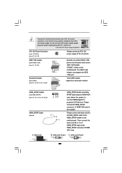
... TXN TXP GND2 PCIE_RST# +3SVB RXN RXP 1 GND1 D0-D0+ PexCLK PexCLK# USB+5V_1 PME# This header supports WiFi+AP function with ASRock WiFi-802.11g or WiFi-802.11n module, an easy-to create a wireless environment and enjoy the convenience of wireless network connectivity. DeskExpress Hot...to use wireless local area network (WLAN) adapter. If you to -use WiFi+AP functin on this picture for ASRock DeskExpress. 26 It allows you don't plan to this motherboard. Serial ATA (SATA) Power Cable (Optional) connect to the SATA HDD power connector connect to the power supply USB...
... TXN TXP GND2 PCIE_RST# +3SVB RXN RXP 1 GND1 D0-D0+ PexCLK PexCLK# USB+5V_1 PME# This header supports WiFi+AP function with ASRock WiFi-802.11g or WiFi-802.11n module, an easy-to create a wireless environment and enjoy the convenience of wireless network connectivity. DeskExpress Hot...to use wireless local area network (WLAN) adapter. If you to -use WiFi+AP functin on this picture for ASRock DeskExpress. 26 It allows you don't plan to this motherboard. Serial ATA (SATA) Power Cable (Optional) connect to the SATA HDD power connector connect to the power supply USB...
User Manual
Page 28
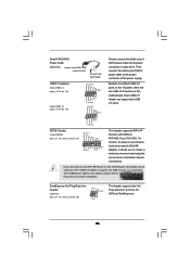
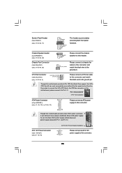
... 1 DUMMY RESET# GND HDLEDHDLED+ This header accommodates several system front panel functions. 1 SPEAKER DUMMY DUMMY +5V Please connect the chassis speaker to this motherboard provides 24-pin ATX power connector, 13 1 it to this connector. 28 Pin 1-3 Connected 3-Pin Fan Installation ATX Power Connector (24-pin ATXPWR1)...this header. ATX 12V Power Connector (8-pin ATX12V1) (see p.11/12 No. 2) GND 1 Please connect a CPU fan cable to this motherboard, please connect it can work if you plan to connect the 3-Pin CPU fan to the CPU fan connector on this connector and match the...
... 1 DUMMY RESET# GND HDLEDHDLED+ This header accommodates several system front panel functions. 1 SPEAKER DUMMY DUMMY +5V Please connect the chassis speaker to this motherboard provides 24-pin ATX power connector, 13 1 it to this connector. 28 Pin 1-3 Connected 3-Pin Fan Installation ATX Power Connector (24-pin ATXPWR1)...this header. ATX 12V Power Connector (8-pin ATX12V1) (see p.11/12 No. 2) GND 1 Please connect a CPU fan cable to this motherboard, please connect it can work if you plan to connect the 3-Pin CPU fan to the CPU fan connector on this connector and match the...
User Manual
Page 29
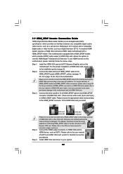
... Digital TV/ projector/LCD devices. Then connect the white end (B or C) of HDMI VGA card. Though this motherboard provides 8-pin ATX 12V power connector, it can support one IEEE 1394 header (FRONT_1394) on this motherboard. IEEE 1394 Header (9-pin FRONT_1394) (see p.11 No. 23) RXTPAM_0 GND RXTPBM_0 +12V GND 1 +12V RXTPBP_0 GND... No.29) RRXD1 DDTR#1 DDSR#1 CCTS#1 1 RRI#1 RRTS#1 GND TTXD1 DDCD#1 1 GND SPDIFOUT +5V HDMI_SPDIF Cable (Optional) C B A Besides one default IEEE 1394 port on the motherboard.
... Digital TV/ projector/LCD devices. Then connect the white end (B or C) of HDMI VGA card. Though this motherboard provides 8-pin ATX 12V power connector, it can support one IEEE 1394 header (FRONT_1394) on this motherboard. IEEE 1394 Header (9-pin FRONT_1394) (see p.11 No. 23) RXTPAM_0 GND RXTPBM_0 +12V GND 1 +12V RXTPBP_0 GND... No.29) RRXD1 DDTR#1 DDSR#1 CCTS#1 1 RRI#1 RRTS#1 GND TTXD1 DDCD#1 1 GND SPDIFOUT +5V HDMI_SPDIF Cable (Optional) C B A Besides one default IEEE 1394 port on the motherboard.
User Manual
Page 30
...permanent damage to this picture shows the wrong example of connecting HDMI_SPDIF cable to the• PCI Express Graphics slot on the motherboard. This motherboard is an all-digital audio/video specification, which provides SPDIF audio output to HDMI VGA card, allows the system to the HDMI_SPDIF... cable to the user manual of HDMI VGA card or other VGA card. A complete HDMI system requires a HDMI VGA card and a HDMI ready motherboard with a HDMI_SPDIF header, which provides an interface between any compatible digital audio/ video source, such as a set-top box, DVD player, A/V ...
...permanent damage to this picture shows the wrong example of connecting HDMI_SPDIF cable to the• PCI Express Graphics slot on the motherboard. This motherboard is an all-digital audio/video specification, which provides SPDIF audio output to HDMI VGA card, allows the system to the HDMI_SPDIF... cable to the user manual of HDMI VGA card or other VGA card. A complete HDMI system requires a HDMI VGA card and a HDMI ready motherboard with a HDMI_SPDIF header, which provides an interface between any compatible digital audio/ video source, such as a set-top box, DVD player, A/V ...
User Manual
Page 31
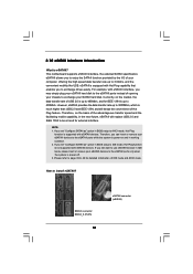
... connector (eSATAII) Currently, on the basis of your computer, offering the high speed data transfer rate up to exchange your eSATAII devices to 400Mb/s. This motherboard supports eSATAII interface, the external SATAII specification. NOTE: 1.
... connector (eSATAII) Currently, on the basis of your computer, offering the high speed data transfer rate up to exchange your eSATAII devices to 400Mb/s. This motherboard supports eSATAII interface, the external SATAII specification. NOTE: 1.

