

User Manual
Page 3
...3.4.1 CPU Configuration 32 3.4.2 Chipset Configuration 33 3.4.3 ACPI Configuration 34 3.4.4 Storage Configuration 35 3.4.5 PCIPnP Configuration 37 3.4.6 Floppy Configuration 38 3.4.7 Super IO Configuration 38 3.4.8 USB Configuration 40 3 Installation 13 Pre-installation Precautions 13 2.1 CPU Installation 14 2.2 Installation of CPU Fan and Heatsink 14 2.3 Installation of Memory Modules (DIMM 15 2.4 Expansion Slots (PCI and PCI Express Slots 16 2.5 Jumpers Setup 17 2.6 Onboard Headers and Connectors 18 2.7 Driver Installation Guide 22 2.8 Installing Windows® 8 / 8 64-bit...
...3.4.1 CPU Configuration 32 3.4.2 Chipset Configuration 33 3.4.3 ACPI Configuration 34 3.4.4 Storage Configuration 35 3.4.5 PCIPnP Configuration 37 3.4.6 Floppy Configuration 38 3.4.7 Super IO Configuration 38 3.4.8 USB Configuration 40 3 Installation 13 Pre-installation Precautions 13 2.1 CPU Installation 14 2.2 Installation of CPU Fan and Heatsink 14 2.3 Installation of Memory Modules (DIMM 15 2.4 Expansion Slots (PCI and PCI Express Slots 16 2.5 Jumpers Setup 17 2.6 Onboard Headers and Connectors 18 2.7 Driver Installation Guide 22 2.8 Installing Windows® 8 / 8 64-bit...
User Manual
Page 5
... ASRock N68-GS4/USB3 FX Quick Installation Guide One ASRock N68-GS4/USB3 FX Support CD Two Serial ATA (SATA) Data Cables (Optional) One I/O Panel Shield 5 In this motherboard, please visit our website for specific information about the model you for purchasing ASRock N68-GS4/USB3 FX motherboard, a reliable motherboard produced under ASRock's consistently stringent quality control. 1. Chapter 3 and 4 contain the configuration guide to BIOS setup and information of the motherboard and step-by-step guide to quality and endurance. Introduction Thank you are using. In case any...
... ASRock N68-GS4/USB3 FX Quick Installation Guide One ASRock N68-GS4/USB3 FX Support CD Two Serial ATA (SATA) Data Cables (Optional) One I/O Panel Shield 5 In this motherboard, please visit our website for specific information about the model you for purchasing ASRock N68-GS4/USB3 FX motherboard, a reliable motherboard produced under ASRock's consistently stringent quality control. 1. Chapter 3 and 4 contain the configuration guide to BIOS setup and information of the motherboard and step-by-step guide to quality and endurance. Introduction Thank you are using. In case any...

User Manual
Page 7
... / Front Speaker / Microphone Storage - 4 x SATA2 3.0Gb/s Connectors, support RAID (RAID 0, RAID 1, RAID 0+1, RAID 5, JBOD), NCQ and Hot Plug Connector - 1 x ATA133 IDE Connector (supports 2 x IDE devices) - 1 x Floppy Connector - 1 x Print Port Header - 1 x Chassis Intrusion Header - 1 x CPU Fan Connector (4-pin) - 1 x Chassis Fan Connector (3-pin) - 1 x 24 pin ATX Power Connector - 1 x 8 pin 12V Power Connector - 1 x Front Panel Audio Connector - 2 x USB 2.0 Headers (Support 4 USB 2.0 ports) - 1 x USB 3.0 Header by Etron EJ188H (Supports 2 USB 3.0 ports) BIOS Feature - 8Mb...
... / Front Speaker / Microphone Storage - 4 x SATA2 3.0Gb/s Connectors, support RAID (RAID 0, RAID 1, RAID 0+1, RAID 5, JBOD), NCQ and Hot Plug Connector - 1 x ATA133 IDE Connector (supports 2 x IDE devices) - 1 x Floppy Connector - 1 x Print Port Header - 1 x Chassis Intrusion Header - 1 x CPU Fan Connector (4-pin) - 1 x Chassis Fan Connector (3-pin) - 1 x 24 pin ATX Power Connector - 1 x 8 pin 12V Power Connector - 1 x Front Panel Audio Connector - 2 x USB 2.0 Headers (Support 4 USB 2.0 ports) - 1 x USB 3.0 Header by Etron EJ188H (Supports 2 USB 3.0 ports) BIOS Feature - 8Mb...
User Manual
Page 22
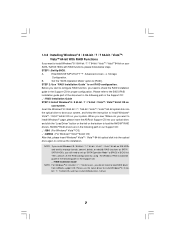
When you to change the BIOS setting. Besides, there is no need for boot devices selection appears. Set the "SATA Operation Mode" option to [IDE]. B. C. Enter BIOS SETUP UTILITY Advanced screen Storage Configuration. Insert the ASRock Support CD into your optical drive to boot your optical drive first. Please select CD-ROM as the boot device. Then, the drivers compatible to your system can work properly. 2.8 Installing Windows® 8 / 8 64-bit / 7 / 7 64-bit / VistaTM / VistaTM 64-bit / XP / XP 64-bit Without RAID Functions If you...
When you to change the BIOS setting. Besides, there is no need for boot devices selection appears. Set the "SATA Operation Mode" option to [IDE]. B. C. Enter BIOS SETUP UTILITY Advanced screen Storage Configuration. Insert the ASRock Support CD into your optical drive to boot your optical drive first. Please select CD-ROM as the boot device. Then, the drivers compatible to your system can work properly. 2.8 Installing Windows® 8 / 8 64-bit / 7 / 7 64-bit / VistaTM / VistaTM 64-bit / XP / XP 64-bit Without RAID Functions If you...
User Manual
Page 23
... install Windows® XP / XP 64-bit on IDE HDDs and want to set RAID configuration. The system will be presented. Enter BIOS SETUP UTILITY Advanced screen Storage Configuration. B. STEP 4: Use "RAID Installation Guide" to install Windows® 8 / 8 64-bit / 7 / 7 64-bit / VistaTM / VistaTM 64-bit on your SATA / SATA2 HDDs with RAID functions, please follow below steps. You can start to configure RAID function, you will see these messages, Please insert a blank formatted diskette into floppy drive A: press any key to start to set RAID configuration...
... install Windows® XP / XP 64-bit on IDE HDDs and want to set RAID configuration. The system will be presented. Enter BIOS SETUP UTILITY Advanced screen Storage Configuration. B. STEP 4: Use "RAID Installation Guide" to install Windows® 8 / 8 64-bit / 7 / 7 64-bit / VistaTM / VistaTM 64-bit on your SATA / SATA2 HDDs with RAID functions, please follow below steps. You can start to configure RAID function, you will see these messages, Please insert a blank formatted diskette into floppy drive A: press any key to start to set RAID configuration...

User Manual
Page 24
... enter "Overclock Mode" option of BIOS setup to set up "SATA Operation Mode" to load RAID driver from [Auto] to install Windows?" Before you still need to [RAID] in the Support CD: .. \ RAID Installation Guide NOTE. Insert the Windows® 8 / 8 64-bit / 7 / 7 64-bit / VistaTM / VistaTM 64-bit optical disk into the optical drive to boot your system, and follow the instruction to load the NVIDIA® RAID drivers. NOTE. page, please insert the ASRock Support CD into the optical drive again to fixed PCI / PCIE...
... enter "Overclock Mode" option of BIOS setup to set up "SATA Operation Mode" to load RAID driver from [Auto] to install Windows?" Before you still need to [RAID] in the Support CD: .. \ RAID Installation Guide NOTE. Insert the Windows® 8 / 8 64-bit / 7 / 7 64-bit / VistaTM / VistaTM 64-bit optical disk into the optical drive to boot your system, and follow the instruction to load the NVIDIA® RAID drivers. NOTE. page, please insert the ASRock Support CD into the optical drive again to fixed PCI / PCIE...

User Manual
Page 27
... frequency. Configuration options: [Disabled] and [Enabled]. PCIE Spread Spectrum This feature will boost to [Enabled] as default. BIOS SETUP UTILITY Main OC Tweaker Advanced H/W Monitor Boot Security Exit CPU Configuration Overclock Mode CPU Frequency (MHz) PCIE Frequency (MHz) Boot Failure Guard Boot Failure Guard Count CPU/LDT Spread Spectrum PCIE Spread Spectrum SATA Spread Spectrum ASRock UCC AMD Turbo Core Technology AMD IO C-State Support CPU Active Core Control [Auto] [200] [100] [Enabled] [3] [Enabled] [Enabled] [Enabled] [Disabled] [Auto] [Enabled] [Disabled] Processor...
... frequency. Configuration options: [Disabled] and [Enabled]. PCIE Spread Spectrum This feature will boost to [Enabled] as default. BIOS SETUP UTILITY Main OC Tweaker Advanced H/W Monitor Boot Security Exit CPU Configuration Overclock Mode CPU Frequency (MHz) PCIE Frequency (MHz) Boot Failure Guard Boot Failure Guard Count CPU/LDT Spread Spectrum PCIE Spread Spectrum SATA Spread Spectrum ASRock UCC AMD Turbo Core Technology AMD IO C-State Support CPU Active Core Control [Auto] [200] [100] [Enabled] [3] [Enabled] [Enabled] [Enabled] [Disabled] [Auto] [Enabled] [Disabled] Processor...

User Manual
Page 28
...will display Processor Maximum Frequency for reference. Processor Maximum Voltage It will display Processor Maximum Voltage for reference. BIOS SETUP UTILITY Main OC Tweaker Advanced H/W Monitor Boot Security Exit CPU Configuration Overclock Mode CPU Frequency (MHz) PCIE Frequency (MHz) Boot Failure Guard Boot Failure Guard Count CPU/LDT Spread Spectrum PCIE Spread Spectrum SATA Spread Spectrum ASRock UCC AMD Turbo Core Technology AMD IO C-State Support CPU Active Core Control [Auto] [200] [100] [Enabled] [3] [Enabled] [Enabled] [Enabled] [Disabled] [Auto] [Enabled] [Disabled] Processor...
...will display Processor Maximum Frequency for reference. Processor Maximum Voltage It will display Processor Maximum Voltage for reference. BIOS SETUP UTILITY Main OC Tweaker Advanced H/W Monitor Boot Security Exit CPU Configuration Overclock Mode CPU Frequency (MHz) PCIE Frequency (MHz) Boot Failure Guard Boot Failure Guard Count CPU/LDT Spread Spectrum PCIE Spread Spectrum SATA Spread Spectrum ASRock UCC AMD Turbo Core Technology AMD IO C-State Support CPU Active Core Control [Auto] [200] [100] [Enabled] [3] [Enabled] [Enabled] [Enabled] [Disabled] [Auto] [Enabled] [Disabled] Processor...

User Manual
Page 29
... DDR3_1600]. DRAM Voltage Use this item. Configuration options: [Auto], [8 Bit] and [16 Bit]. You can be spread out over banks on the same node, or accross nodes, decreasing access contention. 29 The default value is not recommended to [x5 1000 MHz]. Memory Configuration Memory Clock This item can set by the code using [Auto]. Bank Interleaving Interleaving allows memory accesses to select DRAM voltage. Processor Voltage It allows you selecting Hyper-Transport bus speed. NB Frequency Multiplier...
... DDR3_1600]. DRAM Voltage Use this item. Configuration options: [Auto], [8 Bit] and [16 Bit]. You can be spread out over banks on the same node, or accross nodes, decreasing access contention. 29 The default value is not recommended to [x5 1000 MHz]. Memory Configuration Memory Clock This item can set by the code using [Auto]. Bank Interleaving Interleaving allows memory accesses to select DRAM voltage. Processor Voltage It allows you selecting Hyper-Transport bus speed. NB Frequency Multiplier...

User Manual
Page 35
.... IDE Device Configuration You may set the IDE configuration for the device that you want to enable or disable the "OnBoard IDE Controller" feature. 3.4.4 Storage Configuration BIOS SETUP UTILITY Advanced Storage Configuration Onboard IDE Controller Onboard SATA Controller SATA Operation Mode IDE1 Master IDE1 Slave SATAII_1 SATAII_2 SATAII_3 SATAII_4 [Enabled] [Enabled] [IDE] [Hard Disk] [Not Detected] [Not Detected] [Not Detected] [Not Detected] [Not Detected] Options Disabled Enabled +F1 F9 F10 ESC Select Screen Select Item Change Option General Help Load Defaults Save...
.... IDE Device Configuration You may set the IDE configuration for the device that you want to enable or disable the "OnBoard IDE Controller" feature. 3.4.4 Storage Configuration BIOS SETUP UTILITY Advanced Storage Configuration Onboard IDE Controller Onboard SATA Controller SATA Operation Mode IDE1 Master IDE1 Slave SATAII_1 SATAII_2 SATAII_3 SATAII_4 [Enabled] [Enabled] [IDE] [Hard Disk] [Not Detected] [Not Detected] [Not Detected] [Not Detected] [Not Detected] Options Disabled Enabled +F1 F9 F10 ESC Select Screen Select Item Change Option General Help Load Defaults Save...

User Manual
Page 36
... Configuration options: [Disabled], [Auto], [Enabled]. 32Bit Data Transfer Use this item to enable 32-bit access to enable or disable the S.M.A.R.T. (Self-Monitoring, Analysis, and Reporting Technology) feature. PIO Mode Use this item to set the partition of the Primary IDE hard disk drives to enhance hard disk performance by reading or writing more data during each transfer. Make sure to set the PIO mode to active. [CD/DVD]:This is used for IDE ARMD (ATAPI Removable Media Device...
... Configuration options: [Disabled], [Auto], [Enabled]. 32Bit Data Transfer Use this item to enable 32-bit access to enable or disable the S.M.A.R.T. (Self-Monitoring, Analysis, and Reporting Technology) feature. PIO Mode Use this item to set the partition of the Primary IDE hard disk drives to enhance hard disk performance by reading or writing more data during each transfer. Make sure to set the PIO mode to active. [CD/DVD]:This is used for IDE ARMD (ATAPI Removable Media Device...

User Manual
Page 40
... is selected. Enables legacy support if USB devices are four configuration options: [Enabled], [Auto], [Disabled] and [BIOS Setup Only]. USB 3.0 Controller Use this option to use of USB controller. 3.4.8USB Configuration BIOS SETUP UTILITY Advanced USB Configuration USB Controller USB 2.0 Support Legacy USB Support USB 3.0 Controller [Enabled] [Enabled] [Enabled] [Enabled] USB Keyboard/Remote Power On [Disabled] USB Mouse Power On [Disabled] To enable or disable the onboard USB controllers. +F1 F9 F10 ESC Select Screen Select Item Change Option General Help Load Defaults Save and...
... is selected. Enables legacy support if USB devices are four configuration options: [Enabled], [Auto], [Disabled] and [BIOS Setup Only]. USB 3.0 Controller Use this option to use of USB controller. 3.4.8USB Configuration BIOS SETUP UTILITY Advanced USB Configuration USB Controller USB 2.0 Support Legacy USB Support USB 3.0 Controller [Enabled] [Enabled] [Enabled] [Enabled] USB Keyboard/Remote Power On [Disabled] USB Mouse Power On [Disabled] To enable or disable the onboard USB controllers. +F1 F9 F10 ESC Select Screen Select Item Change Option General Help Load Defaults Save and...
User Manual
Page 45
... motherboard settings and hardware options vary, use the setup procedures in your CD-ROM drive. Refer to visit ASRock's website at http://www.asrock.com; or you need to contact ASRock or want to know more information. 4.2 Support CD Information The Support CD that came with the motherboard contains necessary drivers and useful utilities that the motherboard supports. Software Support 4.1 Install Operating System This motherboard supports various Microsoft® Windows® operating systems: 8.1 32-bit...
... motherboard settings and hardware options vary, use the setup procedures in your CD-ROM drive. Refer to visit ASRock's website at http://www.asrock.com; or you need to contact ASRock or want to know more information. 4.2 Support CD Information The Support CD that came with the motherboard contains necessary drivers and useful utilities that the motherboard supports. Software Support 4.1 Install Operating System This motherboard supports various Microsoft® Windows® operating systems: 8.1 32-bit...

Quick Installation Guide
Page 2
...RoHS 8Mb BIOS CHA_FAN1 CLRCMOS1 1 1 CPU Fan Connector (CPU_FAN1) 2 ATX 12V Power Connector (ATX12V1) 3 2 x 240-pin DDR3 DIMM Slots (Dual Channel: DDR3_A1, DDR3_B1) 4 ATX Power Connector (ATXPWR1) 5 Primary IDE Connector (IDE1) 6 SATA2 Connector (SATAII_1 (PORT 0.0)) 7 SATA2 Connector (SATAII_2 (PORT 0.1)) 8 SATA2 Connector (SATAII_3 (PORT 1.0)) 9 SATA2 Connector (SATAII_4 (PORT 1.1)) 10 Chassis Fan Connector (CHA_FAN1) 11 Clear CMOS Jumper (CLRCMOS1) 12 USB 2.0 Header (USB3_4) 13 USB 2.0 Header (USB5_6) 14 Chassis Speaker Header (SPEAKER1) 15 System Panel Header (PANEL1) 16 Print Port Header...
...RoHS 8Mb BIOS CHA_FAN1 CLRCMOS1 1 1 CPU Fan Connector (CPU_FAN1) 2 ATX 12V Power Connector (ATX12V1) 3 2 x 240-pin DDR3 DIMM Slots (Dual Channel: DDR3_A1, DDR3_B1) 4 ATX Power Connector (ATXPWR1) 5 Primary IDE Connector (IDE1) 6 SATA2 Connector (SATAII_1 (PORT 0.0)) 7 SATA2 Connector (SATAII_2 (PORT 0.1)) 8 SATA2 Connector (SATAII_3 (PORT 1.0)) 9 SATA2 Connector (SATAII_4 (PORT 1.1)) 10 Chassis Fan Connector (CHA_FAN1) 11 Clear CMOS Jumper (CLRCMOS1) 12 USB 2.0 Header (USB3_4) 13 USB 2.0 Header (USB5_6) 14 Chassis Speaker Header (SPEAKER1) 15 System Panel Header (PANEL1) 16 Print Port Header...

Quick Installation Guide
Page 5
... LED) 5 ASRock N68-GS4/USB3 FX Motherboard English Supports Wake-On-LAN - Supports UCC feature (Unlock CPU Core) (see CAUTION 1) - Max. Gigabit LAN 10/100/1000 Mb/s - Supports AMD's Cool 'n' QuietTM Technology - Max. FSB 1000 MHz (2.0 GT/s) - Dual Channel DDR3 Memory Technology - 2 x DDR3 DIMM Slots - Supports PXE - 1 x PS/2 Mouse Port - 1 x PS/2 Keyboard Port - 1 x Serial Port: COM1 - 1 x D-Sub Port - 2 x USB 2.0 Ports - 2 x USB 3.0 Ports (Etron EJ188H) - 1 x RJ-45 LAN Port with max. 1.2 Specifications Platform CPU Chipset Memory Expansion Slot Graphics Audio LAN Rear Panel...
... LED) 5 ASRock N68-GS4/USB3 FX Motherboard English Supports Wake-On-LAN - Supports UCC feature (Unlock CPU Core) (see CAUTION 1) - Max. Gigabit LAN 10/100/1000 Mb/s - Supports AMD's Cool 'n' QuietTM Technology - Max. FSB 1000 MHz (2.0 GT/s) - Dual Channel DDR3 Memory Technology - 2 x DDR3 DIMM Slots - Supports PXE - 1 x PS/2 Mouse Port - 1 x PS/2 Keyboard Port - 1 x Serial Port: COM1 - 1 x D-Sub Port - 2 x USB 2.0 Ports - 2 x USB 3.0 Ports (Etron EJ188H) - 1 x RJ-45 LAN Port with max. 1.2 Specifications Platform CPU Chipset Memory Expansion Slot Graphics Audio LAN Rear Panel...

Quick Installation Guide
Page 6
... Connector (4-pin) - 1 x Chassis Fan Connector (3-pin) - 1 x 24 pin ATX Power Connector - 1 x 8 pin 12V Power Connector - 1 x Front Panel Audio Connector - 2 x USB 2.0 Headers (Support 4 USB 2.0 ports) - 1 x USB 3.0 Header by Etron EJ188H (Supports 2 USB 3.0 ports) BIOS Feature - 8Mb AMI Legal BIOS - CPU temperature sensing Monitor - Chassis temperature sensing - - ErP/EuP ready (ErP/EuP ready power supply is required) * For detailed product information, please visit our website: http://www.asrock.com English 6 ASRock N68-GS4/USB3 FX Motherboard Microsoft® Windows...
... Connector (4-pin) - 1 x Chassis Fan Connector (3-pin) - 1 x 24 pin ATX Power Connector - 1 x 8 pin 12V Power Connector - 1 x Front Panel Audio Connector - 2 x USB 2.0 Headers (Support 4 USB 2.0 ports) - 1 x USB 3.0 Header by Etron EJ188H (Supports 2 USB 3.0 ports) BIOS Feature - 8Mb AMI Legal BIOS - CPU temperature sensing Monitor - Chassis temperature sensing - - ErP/EuP ready (ErP/EuP ready power supply is required) * For detailed product information, please visit our website: http://www.asrock.com English 6 ASRock N68-GS4/USB3 FX Motherboard Microsoft® Windows...
Quick Installation Guide
Page 9
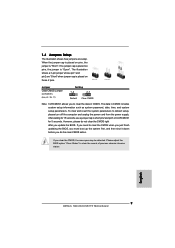
... pins, the jumper is "Short". English 9 ASRock N68-GS4/USB3 FX Motherboard However, please do the clear-CMOS action. 1.4 Jumpers Setup The illustration shows how jumpers are "Short" when jumper cap is placed on pins, the jumper is "Open". If no jumper cap is placed on CLRCMOS1 for 15 seconds, use a jumper cap to clear the data in CMOS includes system setup information such as system password, date, time, and system setup parameters. If you update the BIOS...
... pins, the jumper is "Short". English 9 ASRock N68-GS4/USB3 FX Motherboard However, please do the clear-CMOS action. 1.4 Jumpers Setup The illustration shows how jumpers are "Short" when jumper cap is placed on pins, the jumper is "Open". If no jumper cap is placed on CLRCMOS1 for 15 seconds, use a jumper cap to clear the data in CMOS includes system setup information such as system password, date, time, and system setup parameters. If you update the BIOS...
Quick Installation Guide
Page 14
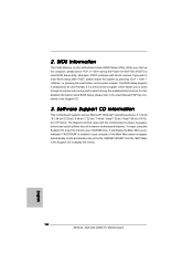
... Power-On-Self-Test (POST) to display the menus. 14 ASRock N68-GS4/USB3 FX Motherboard English If the Main Menu does not appear automatically, locate and double-click on the motherboard stores BIOS Setup Utility. BIOS Information The Flash Memory on the file "ASRSETUP.EXE" from the "BIN" folder in your CD-ROM drive. Software Support CD information This motherboard supports various Microsoft® Windows® operating systems: 8.1 32-bit / 8.1 64-bit / 8 32-bit / 8 64-bit / 7 32-bit / 7 64-bit / VistaTM 32-bit...
... Power-On-Self-Test (POST) to display the menus. 14 ASRock N68-GS4/USB3 FX Motherboard English If the Main Menu does not appear automatically, locate and double-click on the motherboard stores BIOS Setup Utility. BIOS Information The Flash Memory on the file "ASRSETUP.EXE" from the "BIN" folder in your CD-ROM drive. Software Support CD information This motherboard supports various Microsoft® Windows® operating systems: 8.1 32-bit / 8.1 64-bit / 8 32-bit / 8 64-bit / 7 32-bit / 7 64-bit / VistaTM 32-bit...
RAID Installation Guide
Page 7
... / VistaTM 64-bit optical disk into your system. 1.3.2 Installing Windows® 8 / 8 64-bit / 7 / 7 64-bit / VistaTM / VistaTM 64-bit With RAID Functions If you want to install Windows?" Enter BIOS SETUP UTILITY Advanced screen Storage Configuration. page, please insert the ASRock Support CD into the optical drive again to boot your system. Insert the Windows® 8 / 8 64-bit / 7 / 7 64-bit / VistaTM / VistaTM 64-bit optical disk into the optical drive to continue the installation. Please use the native driver to [RAID].
... / VistaTM 64-bit optical disk into your system. 1.3.2 Installing Windows® 8 / 8 64-bit / 7 / 7 64-bit / VistaTM / VistaTM 64-bit With RAID Functions If you want to install Windows?" Enter BIOS SETUP UTILITY Advanced screen Storage Configuration. page, please insert the ASRock Support CD into the optical drive again to boot your system. Insert the Windows® 8 / 8 64-bit / 7 / 7 64-bit / VistaTM / VistaTM 64-bit optical disk into the optical drive to continue the installation. Please use the native driver to [RAID].

RAID Installation Guide
Page 11
... our support CD. After you finish the driver installation, you can create, delete, or rebuild any RAID array. Please read this guide carefully and follow the instructions below screen appears. 11 Please enter NVRAIDMAN by using NVIDIAMAN under Windows environment. For Windows XP / XP 64-bit and Windows 7 / 7 64-bit / Vista / Vista 64-bit, there are different installation procedures. Enter NVRAIDMAN RAID driver is also a "Mediashield" shortcut on the desktop...
... our support CD. After you finish the driver installation, you can create, delete, or rebuild any RAID array. Please read this guide carefully and follow the instructions below screen appears. 11 Please enter NVRAIDMAN by using NVIDIAMAN under Windows environment. For Windows XP / XP 64-bit and Windows 7 / 7 64-bit / Vista / Vista 64-bit, there are different installation procedures. Enter NVRAIDMAN RAID driver is also a "Mediashield" shortcut on the desktop...


