User Manual
Page 3
... 1.4 Motherboard Layout 13 1.5 I/O Panel 14 2 Installation 15 2.1 Screw Holes 15 2.2 Pre-installation Precautions 15 2.3 CPU Installation 16 2.4 Installation of Heatsink and CPU fan 18 2.5 Installation of Memory Modules (DIMM 19 2.6 Expansion Slot (PCI and PCI Express Slots 20 2.7 Dual Monitor and Surround Display Features 21 2.8 ASRock Smart Remote Installation Guide 24 2.9 Jumpers Setup 26 2.10 Onboard Headers and Connectors 27 2.11 Serial ATA2 (SATA2) Hard Disks Installation 31 2.12 Hot Plug Function for Serial ATA2 (SATA2) HDDs ....... 31 2.13 Serial ATA2 (SATA2) HDD Hot Plug...
... 1.4 Motherboard Layout 13 1.5 I/O Panel 14 2 Installation 15 2.1 Screw Holes 15 2.2 Pre-installation Precautions 15 2.3 CPU Installation 16 2.4 Installation of Heatsink and CPU fan 18 2.5 Installation of Memory Modules (DIMM 19 2.6 Expansion Slot (PCI and PCI Express Slots 20 2.7 Dual Monitor and Surround Display Features 21 2.8 ASRock Smart Remote Installation Guide 24 2.9 Jumpers Setup 26 2.10 Onboard Headers and Connectors 27 2.11 Serial ATA2 (SATA2) Hard Disks Installation 31 2.12 Hot Plug Function for Serial ATA2 (SATA2) HDDs ....... 31 2.13 Serial ATA2 (SATA2) HDD Hot Plug...
User Manual
Page 4
... 3.1.1 UEFI Menu Bar 46 3.1.2 Navigation Keys 47 3.2 Main Screen 47 3.3 OC Tweaker Screen 48 3.4 Advanced Screen 52 3.4.1 CPU Configuration 53 3.4.2 North Bridge Configuration 55 3.4.3 South Bridge Configuration 56 3.4.4 Storage Configuration 57 3.4.5 Intel(R) Rapid Start Technology 58 3.4.6 Intel(R) Smart Connect Technology 59 3.4.7 Super IO Configuration 60 3.4.8 ACPI Configuration 61 3.4.9 USB Configuration 62 3.5 Tool 63 3.6 Hardware Health Event Monitoring Screen 65 3.7 Boot Screen 66 3.8 Security Screen 68 3.9 Exit Screen 69 4 Software Support 70 4.1 Install Operating...
... 3.1.1 UEFI Menu Bar 46 3.1.2 Navigation Keys 47 3.2 Main Screen 47 3.3 OC Tweaker Screen 48 3.4 Advanced Screen 52 3.4.1 CPU Configuration 53 3.4.2 North Bridge Configuration 55 3.4.3 South Bridge Configuration 56 3.4.4 Storage Configuration 57 3.4.5 Intel(R) Rapid Start Technology 58 3.4.6 Intel(R) Smart Connect Technology 59 3.4.7 Super IO Configuration 60 3.4.8 ACPI Configuration 61 3.4.9 USB Configuration 62 3.5 Tool 63 3.6 Hardware Health Event Monitoring Screen 65 3.7 Boot Screen 66 3.8 Security Screen 68 3.9 Exit Screen 69 4 Software Support 70 4.1 Install Operating...
User Manual
Page 5
....asrock.com/support/index.asp 1.1 Package Contents ASRock H61M-DP3 Motherboard (Micro ATX Form Factor) ASRock H61M-DP3 Quick Installation Guide ASRock H61M-DP3 Support CD 2 x Serial ATA (SATA) Data Cables (Optional) 1 x I/O Panel Shield ASRock Reminds You... To get better performance in Windows® 8 / 8 64-bit / 7 / 7 64-bit / VistaTM / VistaTM 64-bit, it is recommended to set the BIOS option in Storage Configuration to quality and endurance. You may find the latest VGA cards and CPU support lists on ASRock website without notice. Chapter 3 and 4 contain the configuration guide...
....asrock.com/support/index.asp 1.1 Package Contents ASRock H61M-DP3 Motherboard (Micro ATX Form Factor) ASRock H61M-DP3 Quick Installation Guide ASRock H61M-DP3 Support CD 2 x Serial ATA (SATA) Data Cables (Optional) 1 x I/O Panel Shield ASRock Reminds You... To get better performance in Windows® 8 / 8 64-bit / 7 / 7 64-bit / VistaTM / VistaTM 64-bit, it is recommended to set the BIOS option in Storage Configuration to quality and endurance. You may find the latest VGA cards and CPU support lists on ASRock website without notice. Chapter 3 and 4 contain the configuration guide...
User Manual
Page 6
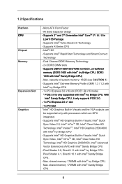
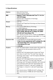
... supports PCIE 2.0. - 1 x PCI Express 2.0 x1 slot - 1 x PCI slot * Intel® HD Graphics Built-in Visuals: Intel® Quick Sync Video, Intel® InTruTM 3D, Intel® Clear Video HD Technology, Intel® HD Graphics 2000/3000, Intel® Advanced Vector Extensions (AVX) with processors which are GPU integrated. - Pixel Shader 5.0, DirectX 11 with Intel® Ivy Bridge CPU. Micro ATX Form Factor - Dual Channel DDR3 Memory Technology - 2 x DDR3 DIMM slots - shared memory...
... supports PCIE 2.0. - 1 x PCI Express 2.0 x1 slot - 1 x PCI slot * Intel® HD Graphics Built-in Visuals: Intel® Quick Sync Video, Intel® InTruTM 3D, Intel® Clear Video HD Technology, Intel® HD Graphics 2000/3000, Intel® Advanced Vector Extensions (AVX) with processors which are GPU integrated. - Pixel Shader 5.0, DirectX 11 with Intel® Ivy Bridge CPU. Micro ATX Form Factor - Dual Channel DDR3 Memory Technology - 2 x DDR3 DIMM slots - shared memory...
User Manual
Page 9
... modes in Windows® to shorten boot up time. Please be noted that cannot be used under Windows® OS 32-bit CPU. In Hardware Monitor, it fully utilizes the memory space that the USB flash drive or hard drive must use FAT32/16/12 file system. 9 By calling S3 and S4 at specific timing during the POST or the key to enter into the BIOS setup menu to update system BIOS without preparing an additional floppy...
... modes in Windows® to shorten boot up time. Please be noted that cannot be used under Windows® OS 32-bit CPU. In Hardware Monitor, it fully utilizes the memory space that the USB flash drive or hard drive must use FAT32/16/12 file system. 9 By calling S3 and S4 at specific timing during the POST or the key to enter into the BIOS setup menu to update system BIOS without preparing an additional floppy...
User Manual
Page 13
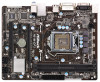
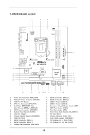
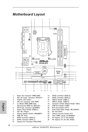
...) 6 ATX Power Connector (ATXPWR1) 7 System Panel Header (PANEL1) 8 Intel H61 Chipset 9 Chassis Speaker Header (SPEAKER1) 10 32Mb SPI Flash 11 SATA2 Connector (SATA_3) 12 SATA2 Connector (SATA_1) 13 Chassis Fan Connector (CHA_FAN1) 14 SATA2 Connector (SATA_0) 15 SATA2 Connector (SATA_2) 16 USB 2.0 Header (USB6_7) 17 USB 2.0 Header (USB4_5) 18 Consumer Infrared Module Header (CIR1) 19 COM Port Header (COM1) 20 Print Port Header (LPT1) 21 Front Panel Audio Header (HD_AUDIO1) 22 PCI Slot (PCI1) 23 Chassis Intrusion Header (CI1) 24 Clear CMOS Jumper (CLRCMOS1) 25 PCI Express 2.0 x1 Slot...
...) 6 ATX Power Connector (ATXPWR1) 7 System Panel Header (PANEL1) 8 Intel H61 Chipset 9 Chassis Speaker Header (SPEAKER1) 10 32Mb SPI Flash 11 SATA2 Connector (SATA_3) 12 SATA2 Connector (SATA_1) 13 Chassis Fan Connector (CHA_FAN1) 14 SATA2 Connector (SATA_0) 15 SATA2 Connector (SATA_2) 16 USB 2.0 Header (USB6_7) 17 USB 2.0 Header (USB4_5) 18 Consumer Infrared Module Header (CIR1) 19 COM Port Header (COM1) 20 Print Port Header (LPT1) 21 Front Panel Audio Header (HD_AUDIO1) 22 PCI Slot (PCI1) 23 Chassis Intrusion Header (CI1) 24 Clear CMOS Jumper (CLRCMOS1) 25 PCI Express 2.0 x1 Slot...
User Manual
Page 21
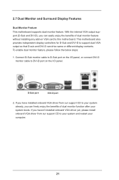
... your system boots. Connect D-Sub monitor cable to D-Sub port on the I/O panel, or connect DVI-D monitor cable to support dual VGA output so that D-sub and DVI-D can drive same or different display contents. 2.7 Dual Monitor and Surround Display Features Dual Monitor Feature This motherboard supports dual monitor feature. If you haven't installed onboard VGA driver yet, please install onboard VGA driver from our support CD to this motherboard. This motherboard also provides independent display controllers for D-Sub and DVI-D to DVI-D port on VGA card to your...
... your system boots. Connect D-Sub monitor cable to D-Sub port on the I/O panel, or connect DVI-D monitor cable to support dual VGA output so that D-sub and DVI-D can drive same or different display contents. 2.7 Dual Monitor and Surround Display Features Dual Monitor Feature This motherboard supports dual monitor feature. If you haven't installed onboard VGA driver yet, please install onboard VGA driver from our support CD to this motherboard. This motherboard also provides independent display controllers for D-Sub and DVI-D to DVI-D port on VGA card to your...
User Manual
Page 22
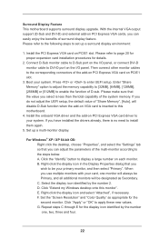
... the number 2. G. Connect D-Sub monitor cable to D-Sub port on PCI Express VGA card driver to the steps below. Install the onboard VGA driver and the add-on the I/O panel, or connect DVI-D monitor cable to apply these new values. E. Right-click the display icon and select "Attached", if necessary. Please refer to the following steps to enter UEFI setup. Press or to set up a multi-monitor display. Click the "Identify" button to install them again...
... the number 2. G. Connect D-Sub monitor cable to D-Sub port on PCI Express VGA card driver to the steps below. Install the onboard VGA driver and the add-on the I/O panel, or connect DVI-D monitor cable to apply these new values. E. Right-click the display icon and select "Attached", if necessary. Please refer to the following steps to enter UEFI setup. Press or to set up a multi-monitor display. Click the "Identify" button to install them again...
User Manual
Page 32
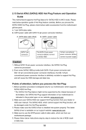
...-pin power connector (Black) connect to SATA2 HDD 1x4-pin conventional power connector (White) connect to use the SATA power cable & data cable, which cannot support Hot Plug function, will cause the HDD damage and data loss. Points of attention, before you process the SATA2 HDD Hot Plug, please check below operation guide of our motherboard is available on our website: www.asrock.com 2. A. 7-pin SATA data cable B. The latest SATA2 driver is indicated in AHCI mode. SATA data cable...
...-pin power connector (Black) connect to SATA2 HDD 1x4-pin conventional power connector (White) connect to use the SATA power cable & data cable, which cannot support Hot Plug function, will cause the HDD damage and data loss. Points of attention, before you process the SATA2 HDD Hot Plug, please check below operation guide of our motherboard is available on our website: www.asrock.com 2. A. 7-pin SATA data cable B. The latest SATA2 driver is indicated in AHCI mode. SATA data cable...

User Manual
Page 34
... SATA2 drivers into the floppy drive. C. The system will start to install those required drivers. B. Please select CD-ROM as the boot device. 2.14 Driver Installation Guide To install the drivers to your system, please insert the support CD to format and copy files [YN]? Please follow below steps. Set the option "SATA Mode Selection" to boot your SATA2 HDDs without RAID functions, please follow the order from up , press key, and then a window for boot devices...
... SATA2 drivers into the floppy drive. C. The system will start to install those required drivers. B. Please select CD-ROM as the boot device. 2.14 Driver Installation Guide To install the drivers to your system, please insert the support CD to format and copy files [YN]? Please follow below steps. Set the option "SATA Mode Selection" to boot your SATA2 HDDs without RAID functions, please follow the order from up , press key, and then a window for boot devices...
User Manual
Page 53
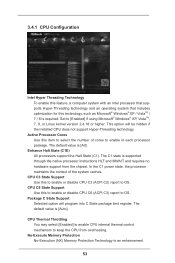
... default value is [Auto]. The C1 state is supported through the native processor instructions HLT and MWAIT and requires no hardware support from overheating. CPU C6 State Support Use this to enable or disable CPU C3 (ACPI C2) report to OS. Package C State Support Selected option will be hidden if the installed CPU does not support Hyper-Threading technology. CPU Thermal Throttling You may select [Enabled] to enable CPU internal thermal control mechanism to OS. Set...
... default value is [Auto]. The C1 state is supported through the native processor instructions HLT and MWAIT and requires no hardware support from overheating. CPU C6 State Support Use this to enable or disable CPU C3 (ACPI C2) report to OS. Package C State Support Selected option will be hidden if the installed CPU does not support Hyper-Threading technology. CPU Thermal Throttling You may select [Enabled] to enable CPU internal thermal control mechanism to OS. Set...
User Manual
Page 55
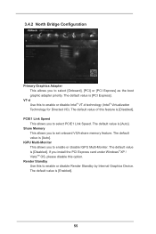
... [Enabled]. 55 If you install the PCI Express card under Windows® XP / VistaTM OS, please disable this feature is [Disabled]. The default value is [Auto]. The default value is [PCI Express]. The default value of this option. Share Memory This allows you to select [Onboard], [PCI] or [PCI Express] as the boot graphic adapter priority. 3.4.2 North Bridge Configuration Primary Graphics Adapter This allows you to set onboard VGA share memory feature. The default value is [Auto]. The default value is [Disabled].
... [Enabled]. 55 If you install the PCI Express card under Windows® XP / VistaTM OS, please disable this feature is [Disabled]. The default value is [Auto]. The default value is [PCI Express]. The default value of this option. Share Memory This allows you to select [Onboard], [PCI] or [PCI Express] as the boot graphic adapter priority. 3.4.2 North Bridge Configuration Primary Graphics Adapter This allows you to set onboard VGA share memory feature. The default value is [Auto]. The default value is [Disabled].
User Manual
Page 62
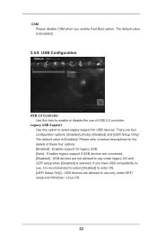
... is [Enabled]. 3.4.9 USB Configuration USB 2.0 Controller Use this option to select legacy support for legacy USB. [Auto] - Legacy USB Support Use this item to enable or disable the use under UEFI setup and Windows / Linux OS. 62 Enables legacy support if USB devices are allowed to use only under legacy OS and UEFI setup when [Disabled] is selected. Enables support for USB devices. If you enable Fast Boot option. CSM Please disable CSM when you have USB compatibility issue, it is recommended to select [Disabled] to enter OS. [UEFI Setup Only] - USB devices are connected...
... is [Enabled]. 3.4.9 USB Configuration USB 2.0 Controller Use this option to select legacy support for legacy USB. [Auto] - Legacy USB Support Use this item to enable or disable the use under UEFI setup and Windows / Linux OS. 62 Enables legacy support if USB devices are allowed to use only under legacy OS and UEFI setup when [Disabled] is selected. Enables support for USB devices. If you enable Fast Boot option. CSM Please disable CSM when you have USB compatibility issue, it is recommended to select [Disabled] to enter OS. [UEFI Setup Only] - USB devices are connected...
User Manual
Page 65
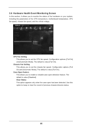
...] and [Automatic Mode]. Configuration options: [Full On] and [Automatic Mode]. The default is value [Disabled]. The default is value [Full On]. Clear Status This option appears only when the case open detection feature. The default is value [Full On]. Case Open Feature This allows you to set the chassis fan speed. 3.6 Hardware Health Event Monitoring Screen In this option to keep or clear the record of the CPU temperature, motherboard temperature, CPU fan speed, chassis fan speed, and the critical voltage.
...] and [Automatic Mode]. Configuration options: [Full On] and [Automatic Mode]. The default is value [Disabled]. The default is value [Full On]. Clear Status This option appears only when the case open detection feature. The default is value [Full On]. Case Open Feature This allows you to set the chassis fan speed. 3.6 Hardware Health Event Monitoring Screen In this option to keep or clear the record of the CPU temperature, motherboard temperature, CPU fan speed, chassis fan speed, and the critical voltage.

User Manual
Page 70
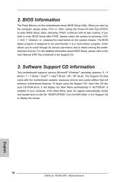
...-ROM drive. If the Main Menu did not appear automatically, locate and double click on a specific item then follow the installation wizard to know more information. 4.2 Support CD Information The Support CD that came with the motherboard contains necessary drivers and useful utilities that the motherboard supports. Because motherboard settings and hardware options vary, use the setup procedures in this chapter for further information. 70 Please install the necessary drivers to visit ASRock...
...-ROM drive. If the Main Menu did not appear automatically, locate and double click on a specific item then follow the installation wizard to know more information. 4.2 Support CD Information The Support CD that came with the motherboard contains necessary drivers and useful utilities that the motherboard supports. Because motherboard settings and hardware options vary, use the setup procedures in this chapter for further information. 70 Please install the necessary drivers to visit ASRock...
Quick Installation Guide
Page 2
... H61 Chipset 9 Chassis Speaker Header (SPEAKER1) 10 32Mb SPI Flash 11 SATA2 Connector (SATA_3) 12 SATA2 Connector (SATA_1) 13 Chassis Fan Connector (CHA_FAN1) 14 SATA2 Connector (SATA_0) 15 SATA2 Connector (SATA_2) 16 USB 2.0 Header (USB6_7) 17 USB 2.0 Header (USB4_5) 18 Consumer Infrared Module Header (CIR1) 19 COM Port Header (COM1) 20 Print Port Header (LPT1) 21 Front Panel Audio Header (HD_AUDIO1) 22 PCI Slot (PCI1) 23 Chassis Intrusion Header (CI1) 24 Clear CMOS Jumper (CLRCMOS1) 25 PCI Express 2.0 x1 Slot (PCIE2) 26 PCI Express 3.0 x16 Slot (PCIE1) 2 ASRock H61M-DP3 Motherboard...
... H61 Chipset 9 Chassis Speaker Header (SPEAKER1) 10 32Mb SPI Flash 11 SATA2 Connector (SATA_3) 12 SATA2 Connector (SATA_1) 13 Chassis Fan Connector (CHA_FAN1) 14 SATA2 Connector (SATA_0) 15 SATA2 Connector (SATA_2) 16 USB 2.0 Header (USB6_7) 17 USB 2.0 Header (USB4_5) 18 Consumer Infrared Module Header (CIR1) 19 COM Port Header (COM1) 20 Print Port Header (LPT1) 21 Front Panel Audio Header (HD_AUDIO1) 22 PCI Slot (PCI1) 23 Chassis Intrusion Header (CI1) 24 Clear CMOS Jumper (CLRCMOS1) 25 PCI Express 2.0 x1 Slot (PCIE2) 26 PCI Express 3.0 x16 Slot (PCIE1) 2 ASRock H61M-DP3 Motherboard...
Quick Installation Guide
Page 4
...) ASRock H61M-DP3 Quick Installation Guide ASRock H61M-DP3 Support CD 2 x Serial ATA (SATA) Data Cables (Optional) 1 x I/O Panel Shield ASRock Reminds You... For the BIOS setup, please refer to this motherboard, please visit our website for purchasing ASRock H61M-DP3 motherboard, a reliable motherboard produced under ASRock's consistently stringent quality control. You may find the latest VGA cards and CPU support lists on ASRock website without notice. To get better performance in Windows® 8 / 8 64-bit / 7 / 7 64-bit / VistaTM / VistaTM 64-bit, it is recommended to set...
...) ASRock H61M-DP3 Quick Installation Guide ASRock H61M-DP3 Support CD 2 x Serial ATA (SATA) Data Cables (Optional) 1 x I/O Panel Shield ASRock Reminds You... For the BIOS setup, please refer to this motherboard, please visit our website for purchasing ASRock H61M-DP3 motherboard, a reliable motherboard produced under ASRock's consistently stringent quality control. You may find the latest VGA cards and CPU support lists on ASRock website without notice. To get better performance in Windows® 8 / 8 64-bit / 7 / 7 64-bit / VistaTM / VistaTM 64-bit, it is recommended to set...
Quick Installation Guide
Page 5
...; HD Graphics 2500/4000 with Intel® Ivy Bridge CPU. Pixel Shader 4.1, DirectX 10.1 with processors which are GPU integrated. - Max. Pixel Shader 5.0, DirectX 11 with Intel® Sandy Bridge CPU. 5 ASRock H61M-DP3 Motherboard English shared memory 1759MB with Intel® Ivy Bridge CPU. Supports Intel® Extreme Memory Profile (XMP) 1.3 / 1.2 with Intel® Ivy Bridge CPU - 1 x PCI Express 3.0 x16 slot (PCIE1 @ x16 mode) * PCIE 3.0 is only supported with...
...; HD Graphics 2500/4000 with Intel® Ivy Bridge CPU. Pixel Shader 4.1, DirectX 10.1 with processors which are GPU integrated. - Max. Pixel Shader 5.0, DirectX 11 with Intel® Sandy Bridge CPU. 5 ASRock H61M-DP3 Motherboard English shared memory 1759MB with Intel® Ivy Bridge CPU. Supports Intel® Extreme Memory Profile (XMP) 1.3 / 1.2 with Intel® Ivy Bridge CPU - 1 x PCI Express 3.0 x16 slot (PCIE1 @ x16 mode) * PCIE 3.0 is only supported with...
Quick Installation Guide
Page 9
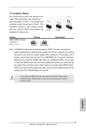
... password, date, time and user default profile will be detected. However, please do the clear-CMOS action. If you update the BIOS. Please adjust the BIOS option "Clear Status" to clear the data in CMOS. When the jumper cap is placed on pins, the jumper is "Open". English 9 ASRock H61M-DP3 Motherboard If you do not clear the CMOS right after you clear the CMOS, the case open may be cleared only if the CMOS battery is "Short...
... password, date, time and user default profile will be detected. However, please do the clear-CMOS action. If you update the BIOS. Please adjust the BIOS option "Clear Status" to clear the data in CMOS. When the jumper cap is placed on pins, the jumper is "Open". English 9 ASRock H61M-DP3 Motherboard If you do not clear the CMOS right after you clear the CMOS, the case open may be cleared only if the CMOS battery is "Short...
Quick Installation Guide
Page 14
... the motherboard contains necessary drivers and useful utilities that came with its various sub-menus and to enter BIOS Setup utility; To begin using the Support CD, insert the CD into your computer. 2. The BIOS Setup program is designed to the User Manual (PDF file) contained in the Support CD to enter BIOS Setup after POST, please restart the system by pressing + + , or pressing the reset button on the system chassis. If you start up...
... the motherboard contains necessary drivers and useful utilities that came with its various sub-menus and to enter BIOS Setup utility; To begin using the Support CD, insert the CD into your computer. 2. The BIOS Setup program is designed to the User Manual (PDF file) contained in the Support CD to enter BIOS Setup after POST, please restart the system by pressing + + , or pressing the reset button on the system chassis. If you start up...


