User Manual
Page 4
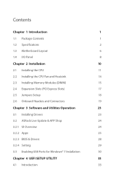
...1.2 Specifications 2 1.3 Motherboard Layout 6 1.4 I/O Panel 8 Chapter 2 Installation 10 2.1 Installing the CPU 11 2.2 Installing the CPU Fan and Heatsink 14 2.3 Installing Memory Modules (DIMM) 15 2.4 Expansion Slots (PCI Express Slots) 17 2.5 Jumpers Setup 18 2.6 Onboard Headers and Connectors 19 Chapter 3 Software and Utilities Operation 23 3.1 Installing Drivers 23 3.2 ASRock Live Update & APP Shop 24 3.2.1 UI Overview 24 3.2.2 Apps 25 3.2.3 BIOS & Drivers 28 3.2.4 Setting 29 3.3 Enabling USB Ports for Windows® 7 Installation 30 Chapter 4 UEFI SETUP...
...1.2 Specifications 2 1.3 Motherboard Layout 6 1.4 I/O Panel 8 Chapter 2 Installation 10 2.1 Installing the CPU 11 2.2 Installing the CPU Fan and Heatsink 14 2.3 Installing Memory Modules (DIMM) 15 2.4 Expansion Slots (PCI Express Slots) 17 2.5 Jumpers Setup 18 2.6 Onboard Headers and Connectors 19 Chapter 3 Software and Utilities Operation 23 3.1 Installing Drivers 23 3.2 ASRock Live Update & APP Shop 24 3.2.1 UI Overview 24 3.2.2 Apps 25 3.2.3 BIOS & Drivers 28 3.2.4 Setting 29 3.3 Enabling USB Ports for Windows® 7 Installation 30 Chapter 4 UEFI SETUP...
User Manual
Page 6
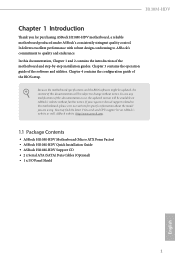
... utilities. In this documentation, Chapter 1 and 2 contains the introduction of this motherboard, please visit our website for purchasing ASRock H110M-HDV motherboard, a reliable motherboard produced under ASRock's consistently stringent quality control. Chapter 4 contains the configuration guide of the BIOS setup. ASRock website http://www.asrock.com. 1.1 Package Contents • ASRock H110M-HDV Motherboard (Micro ATX Form Factor) • ASRock H110M-HDV Quick Installation Guide • ASRock H110M-HDV Support CD • 2 x Serial ATA (SATA) Data Cables (Optional) • 1 x I/O Panel...
... utilities. In this documentation, Chapter 1 and 2 contains the introduction of this motherboard, please visit our website for purchasing ASRock H110M-HDV motherboard, a reliable motherboard produced under ASRock's consistently stringent quality control. Chapter 4 contains the configuration guide of the BIOS setup. ASRock website http://www.asrock.com. 1.1 Package Contents • ASRock H110M-HDV Motherboard (Micro ATX Form Factor) • ASRock H110M-HDV Quick Installation Guide • ASRock H110M-HDV Support CD • 2 x Serial ATA (SATA) Data Cables (Optional) • 1 x I/O Panel...
User Manual
Page 8
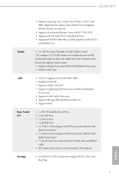
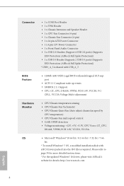
...; Supports LAN Cable Detection • Supports Energy Efficient Ethernet 802.3az • Supports PXE Rear Panel I/O • 1 x PS/2 Mouse/Keyboard Port • 1 x D-Sub Port • 1 x DVI-D Port • 1 x HDMI Port • 4 x USB 2.0 Ports (Supports ESD Protection (ASRock Full Spike Protection)) • 2 x USB 3.0 Ports (Supports ESD Protection (ASRock Full Spike Protection)) • 1 x RJ-45 LAN Port with LED (ACT/LINK LED and SPEED LED) • HD Audio Jacks: Line in / Front Speaker / Microphone Storage • 4 x SATA3 6.0 Gb/s Connectors, support NCQ, AHCI and Hot Plug...
...; Supports LAN Cable Detection • Supports Energy Efficient Ethernet 802.3az • Supports PXE Rear Panel I/O • 1 x PS/2 Mouse/Keyboard Port • 1 x D-Sub Port • 1 x DVI-D Port • 1 x HDMI Port • 4 x USB 2.0 Ports (Supports ESD Protection (ASRock Full Spike Protection)) • 2 x USB 3.0 Ports (Supports ESD Protection (ASRock Full Spike Protection)) • 1 x RJ-45 LAN Port with LED (ACT/LINK LED and SPEED LED) • HD Audio Jacks: Line in / Front Speaker / Microphone Storage • 4 x SATA3 6.0 Gb/s Connectors, support NCQ, AHCI and Hot Plug...
User Manual
Page 9
... CASE OPEN detection • Voltage monitoring: +12V, +5V, +3.3V, CPU Vcore, GT_CPU, DRAM, VPPM, PCH 1.0V, VCCIO, VCCSA OS • Microsoft® Windows® 10 64-bit / 8.1 64-bit / 7 32-bit / 7 64- Connector • 1 x COM Port Header • 1 x TPM Header • 1 x Chassis Intrusion and Speaker Header • 1 x CPU Fan Connector (4-pin) • 1 x Chassis Fan Connector (4-pin) • 1 x 24 pin ATX Power Connector • 1 x 4 pin 12V Power Connector • 1 x Front Panel Audio Connector • 2 x USB 2.0 Headers (Support 4 USB 2.0 ports) (Supports ESD Protection (ASRock...
... CASE OPEN detection • Voltage monitoring: +12V, +5V, +3.3V, CPU Vcore, GT_CPU, DRAM, VPPM, PCH 1.0V, VCCIO, VCCSA OS • Microsoft® Windows® 10 64-bit / 8.1 64-bit / 7 32-bit / 7 64- Connector • 1 x COM Port Header • 1 x TPM Header • 1 x Chassis Intrusion and Speaker Header • 1 x CPU Fan Connector (4-pin) • 1 x Chassis Fan Connector (4-pin) • 1 x 24 pin ATX Power Connector • 1 x 4 pin 12V Power Connector • 1 x Front Panel Audio Connector • 2 x USB 2.0 Headers (Support 4 USB 2.0 ports) (Supports ESD Protection (ASRock...
User Manual
Page 11
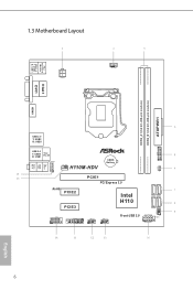
1.3 Motherboard Layout PS2 Keyboard /Mouse USB 3.0 T: USB0 B: USB1 ATX12V1 CPU_FAN1 VGA1 DVI1 ATXPWR1 DDR4_A1 (64 bit, 288-pin module) DDR4_B1 (64 bit, 288-pin module) HDMI1 SATA3_2_3 SPK_CI1 SATA3_4_5 Top: LINE IN Center: FRONT Bottom: MIC IN USB 2.0 T: USB2 B: USB3 1 TPMS1 USB 2.0 T: USB0 Top: B: USB1 RJ-45 HD_AUDIO1 CHA_FAN1 H110M-HDV CMOS Battery CLRMOS1 1 1 PCIE1 PCI Express 3.0 RoHS PCIE2 PCIE3 Intel H110 COM1 1 USB3_4_5 USB_6_7 1 1 USB_4_5 1 Front USB 3.0 PLED PWRBTN 1 HDLED RESET 1 PANEL1 6 English
1.3 Motherboard Layout PS2 Keyboard /Mouse USB 3.0 T: USB0 B: USB1 ATX12V1 CPU_FAN1 VGA1 DVI1 ATXPWR1 DDR4_A1 (64 bit, 288-pin module) DDR4_B1 (64 bit, 288-pin module) HDMI1 SATA3_2_3 SPK_CI1 SATA3_4_5 Top: LINE IN Center: FRONT Bottom: MIC IN USB 2.0 T: USB2 B: USB3 1 TPMS1 USB 2.0 T: USB0 Top: B: USB1 RJ-45 HD_AUDIO1 CHA_FAN1 H110M-HDV CMOS Battery CLRMOS1 1 1 PCIE1 PCI Express 3.0 RoHS PCIE2 PCIE3 Intel H110 COM1 1 USB3_4_5 USB_6_7 1 1 USB_4_5 1 Front USB 3.0 PLED PWRBTN 1 HDLED RESET 1 PANEL1 6 English
User Manual
Page 12
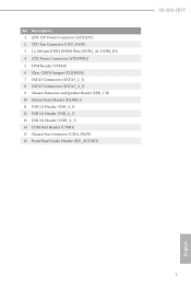
Description 1 ATX 12V Power Connector (ATX12V1) 2 CPU Fan Connector (CPU_FAN1) 3 2 x 288-pin DDR4 DIMM Slots (DDR4_A1, DDR4_B1) 4 ATX Power Connector (ATXPWR1) 5 TPM Header (TPMS1) 6 Clear CMOS Jumper (CLRMOS1) 7 SATA3 Connectors (SATA3_2_3) 8 SATA3 Connectors (SATA3_4_5) 9 Chassis Intrusion and Speaker Header (SPK_CI1) 10 System Panel Header (PANEL1) 11 USB 2.0 Header (USB_4_5) 12 USB 2.0 Header (USB_6_7) 13 USB 3.0 Header (USB3_4_5) 14 COM Port Header (COM1) 15 Chassis Fan Connector (CHA_FAN1) 16 Front Panel Audio Header (HD_AUDIO1) H110M-HDV English 7 No.
Description 1 ATX 12V Power Connector (ATX12V1) 2 CPU Fan Connector (CPU_FAN1) 3 2 x 288-pin DDR4 DIMM Slots (DDR4_A1, DDR4_B1) 4 ATX Power Connector (ATXPWR1) 5 TPM Header (TPMS1) 6 Clear CMOS Jumper (CLRMOS1) 7 SATA3 Connectors (SATA3_2_3) 8 SATA3 Connectors (SATA3_4_5) 9 Chassis Intrusion and Speaker Header (SPK_CI1) 10 System Panel Header (PANEL1) 11 USB 2.0 Header (USB_4_5) 12 USB 2.0 Header (USB_6_7) 13 USB 3.0 Header (USB3_4_5) 14 COM Port Header (COM1) 15 Chassis Fan Connector (CHA_FAN1) 16 Front Panel Audio Header (HD_AUDIO1) H110M-HDV English 7 No.
User Manual
Page 22
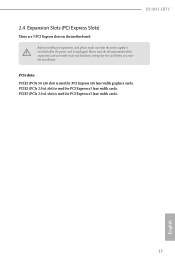
... lane width cards. 17 English PCIE2 (PCIe 2.0 x1 slot) is used for PCI Express x16 lane width graphics cards. PCIe slots: PCIE1 (PCIe 3.0 x16 slot) is used for PCI Express x1 lane width cards. Please read the documentation of the expansion card and make sure that the power supply is switched off or the power cord is used for the card before you start the installation. PCIE3 (PCIe 2.0 x1 slot) is unplugged. H110M-HDV 2.4 Expansion Slots (PCI Express Slots) There are 3 PCI Express slots on the motherboard.
... lane width cards. 17 English PCIE2 (PCIe 2.0 x1 slot) is used for PCI Express x16 lane width graphics cards. PCIe slots: PCIE1 (PCIe 3.0 x16 slot) is used for PCI Express x1 lane width cards. Please read the documentation of the expansion card and make sure that the power supply is switched off or the power cord is used for the card before you start the installation. PCIE3 (PCIe 2.0 x1 slot) is unplugged. H110M-HDV 2.4 Expansion Slots (PCI Express Slots) There are 3 PCI Express slots on the motherboard.
User Manual
Page 23
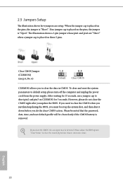
... shut it down before you need to default setup, please turn off the computer and unplug the power cord from the power supply. If you do not clear the CMOS right after you clear the CMOS, the case open may be cleared only if the CMOS battery is placed on the pins, the jumper is "Short". Please adjust the BIOS option "Clear Status" to clear the record of previous chassis intrusion status.
... shut it down before you need to default setup, please turn off the computer and unplug the power cord from the power supply. If you do not clear the CMOS right after you clear the CMOS, the case open may be cleared only if the CMOS battery is placed on the pins, the jumper is "Short". Please adjust the BIOS option "Clear Status" to clear the record of previous chassis intrusion status.
User Manual
Page 25
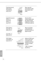
... SATA3 connectors support SATA data cables for internal storage devices with USB_6_7. Each USB 3.0 header can support two ports. SATA3_4 SATA3_2 SATA3_5 SATA3_3 USB 2.0 Headers (9-pin USB_4_5) (see p.6, No. 11) (9-pin USB_6_7) (see p.6, No. 12) USB 3.0 Header (19-pin USB3_4_5) (see p.6, No. 7) SPEAKER DUMMY DUMMY +5V 1 SIGNAL GND DUMMY Please connect the chassis intrusion and the chassis speaker to 6.0 Gb/s data transfer rate. Each USB 2.0 header can support two ports. * USB3_4_5 is one header on this motherboard. Chassis Intrusion and Speaker Header (7-pin...
... SATA3 connectors support SATA data cables for internal storage devices with USB_6_7. Each USB 3.0 header can support two ports. SATA3_4 SATA3_2 SATA3_5 SATA3_3 USB 2.0 Headers (9-pin USB_4_5) (see p.6, No. 11) (9-pin USB_6_7) (see p.6, No. 12) USB 3.0 Header (19-pin USB3_4_5) (see p.6, No. 7) SPEAKER DUMMY DUMMY +5V 1 SIGNAL GND DUMMY Please connect the chassis intrusion and the chassis speaker to 6.0 Gb/s data transfer rate. Each USB 2.0 header can support two ports. * USB3_4_5 is one header on this motherboard. Chassis Intrusion and Speaker Header (7-pin...
User Manual
Page 26
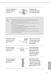
... This motherboard pro- To activate the front mic, go to function correctly. D. E. Chassis Fan Connector (4-pin CHA_FAN1) (see p.6, No. 15) FAN_SPEED_CONTROL CHA_FAN_SPEED FAN_VOLTAGE GND Please connect fan cables to the fan connector and match the black wire to install your system. 2. FAN_VOLTAGE_CONTROL GND FAN_SPEED_CONTROL vides a 4-Pin CPU fan (Quiet Fan) connector. If you plan to the front audio panel. 1. C. Please follow the instructions in the Realtek Control panel and adjust "Recording Volume". B. H110M-HDV Front Panel Audio Header (9-pin...
... This motherboard pro- To activate the front mic, go to function correctly. D. E. Chassis Fan Connector (4-pin CHA_FAN1) (see p.6, No. 15) FAN_SPEED_CONTROL CHA_FAN_SPEED FAN_VOLTAGE GND Please connect fan cables to the fan connector and match the black wire to install your system. 2. FAN_VOLTAGE_CONTROL GND FAN_SPEED_CONTROL vides a 4-Pin CPU fan (Quiet Fan) connector. If you plan to the front audio panel. 1. C. Please follow the instructions in the Realtek Control panel and adjust "Recording Volume". B. H110M-HDV Front Panel Audio Header (9-pin...
User Manual
Page 28
.... Utilities Menu The Utilities Menu shows the application software that enhance the motherboard's features. Click on a specific item then follow the order from top to bottom to your system will be auto-detected and listed on the file "ASRSETUP.EXE" in your CD-ROM drive. If the Main Menu does not appear automatically, locate and double click on the support CD driver page. H110M-HDV Chapter 3 Software and Utilities Operation 3.1 Installing Drivers The Support...
.... Utilities Menu The Utilities Menu shows the application software that enhance the motherboard's features. Click on a specific item then follow the order from top to bottom to your system will be auto-detected and listed on the file "ASRSETUP.EXE" in your CD-ROM drive. If the Main Menu does not appear automatically, locate and double click on the support CD driver page. H110M-HDV Chapter 3 Software and Utilities Operation 3.1 Installing Drivers The Support...
User Manual
Page 35
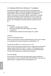
... included in UEFI SETUP UTILITY > Advanced > USB Configuration, which allows the USB port to create a new ISO file with the Intel® USB 3.0 eXtensible Host Controller (xHCI) drivers packed into the ISO file. Then use the new patched Windows® 7 installation USB drive to disabled after the installation. Due to that fact that XHCI is an optical disc drive, PS/2 ports and PS/2 Keyboard or mouse on their support for the USB ports to install Windows®...
... included in UEFI SETUP UTILITY > Advanced > USB Configuration, which allows the USB port to create a new ISO file with the Intel® USB 3.0 eXtensible Host Controller (xHCI) drivers packed into the ISO file. Then use the new patched Windows® 7 installation USB drive to disabled after the installation. Due to that fact that XHCI is an optical disc drive, PS/2 ports and PS/2 Keyboard or mouse on their support for the USB ports to install Windows®...
User Manual
Page 36
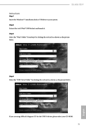
Step 2 Extract the tool (Win7 USB Patcher) and launch it. H110M-HDV Instructions Step 1 Insert the Windows® 7 installation disk or USB drive to your CD-ROM. 31 English If you are using ASRock's Support CD for the USB 3.0 driver, please select your system. Step 3 Select the "Win7 Folder" from Step1 by clicking the red circle as shown as the picture below . Step 4 Select the "USB Driver Folder" by clicking the red circle as shown as the picture below .
Step 2 Extract the tool (Win7 USB Patcher) and launch it. H110M-HDV Instructions Step 1 Insert the Windows® 7 installation disk or USB drive to your CD-ROM. 31 English If you are using ASRock's Support CD for the USB 3.0 driver, please select your system. Step 3 Select the "Win7 Folder" from Step1 by clicking the red circle as shown as the picture below . Step 4 Select the "USB Driver Folder" by clicking the red circle as shown as the picture below .
User Manual
Page 38
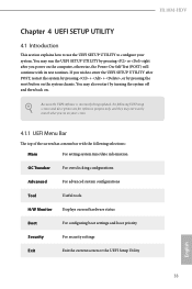
... match what you power on . H110M-HDV Chapter 4 UEFI SETUP UTILITY 4.1 Introduction This section explains how to use the UEFI SETUP UTILITY to enter the UEFI SETUP UTILITY after you see on the system chassis. Because the UEFI software is constantly being updated, the following selections: Main For setting system time/date information OC Tweaker For overclocking configurations Advanced For advanced system configurations Tool Useful tools H/W Monitor Displays current hardware status Boot For configuring boot settings and boot priority Security For...
... match what you power on . H110M-HDV Chapter 4 UEFI SETUP UTILITY 4.1 Introduction This section explains how to use the UEFI SETUP UTILITY to enter the UEFI SETUP UTILITY after you see on the system chassis. Because the UEFI software is constantly being updated, the following selections: Main For setting system time/date information OC Tweaker For overclocking configurations Advanced For advanced system configurations Tool Useful tools H/W Monitor Displays current hardware status Boot For configuring boot settings and boot priority Security For...
User Manual
Page 53
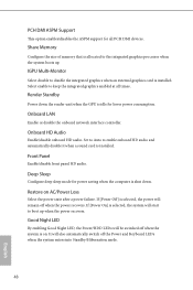
... installed. It will remain off the Power and Keyboard LEDs when the system enters into Standby/Hibernation mode. 48 English IGPU Multi-Monitor Select disable to disable the integrated graphics when an external graphics card is allocated to enable onboard HD audio and automatically disable it when a sound card is selected, the power will also automatically switch off when the power recovers. Onboard LAN Enable or disable the onboard network interface controller. PCH DMI ASPM Support This option enables/disables the ASPM support...
... installed. It will remain off the Power and Keyboard LEDs when the system enters into Standby/Hibernation mode. 48 English IGPU Multi-Monitor Select disable to disable the integrated graphics when an external graphics card is allocated to enable onboard HD audio and automatically disable it when a sound card is selected, the power will also automatically switch off when the power recovers. Onboard LAN Enable or disable the onboard network interface controller. PCH DMI ASPM Support This option enables/disables the ASPM support...
User Manual
Page 55
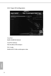
Serial Port Address Select the address of the Serial port. PS2 Y-Cable Enable the PS2 Y-Cable or set this option to Auto. 50 English 4.4.4 Super IO Configuration Serial Port Enable or disable the Serial port.
Serial Port Address Select the address of the Serial port. PS2 Y-Cable Enable the PS2 Y-Cable or set this option to Auto. 50 English 4.4.4 Super IO Configuration Serial Port Enable or disable the Serial port.
User Manual
Page 60
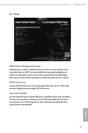
... access at specified times via an USB storage device, then downloads and installs the other users. In order to prevent users from our support CD, Easy Driver Installer is a handy tool in the UEFI that don't have an optical disk drive to install the drivers from bypassing OMG, guest accounts without permission to modify the system time are able to your PC. Please setup network configuration before using UEFI Tech Service. 4.5 Tools H110M-HDV...
... access at specified times via an USB storage device, then downloads and installs the other users. In order to prevent users from our support CD, Easy Driver Installer is a handy tool in the UEFI that don't have an optical disk drive to install the drivers from bypassing OMG, guest accounts without permission to modify the system time are able to your PC. Please setup network configuration before using UEFI Tech Service. 4.5 Tools H110M-HDV...
User Manual
Page 62
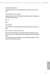
... Flash Save UEFI files in your UEFI. Internet Flash - Please setup network configuration before using Internet Flash. *For BIOS backup and recovery purpose, it returns to update your USB pen drive before it is enabled. The higher the value, the faster the fan speed. DHCP (Auto IP), Auto ASRock Internet Flash downloads and updates the latest UEFI firmware version from our servers for you. H110M-HDV Dehumidifier Duration Configure the duration of the CPU fan while Dehumidifier is recommended to plug in your USB storage device...
... Flash Save UEFI files in your UEFI. Internet Flash - Please setup network configuration before using Internet Flash. *For BIOS backup and recovery purpose, it returns to update your USB pen drive before it is enabled. The higher the value, the faster the fan speed. DHCP (Auto IP), Auto ASRock Internet Flash downloads and updates the latest UEFI firmware version from our servers for you. H110M-HDV Dehumidifier Duration Configure the duration of the CPU fan while Dehumidifier is recommended to plug in your USB storage device...
User Manual
Page 63
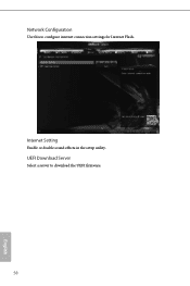
UEFI Download Server Select a server to configure internet connection settings for Internet Flash. Network Configuration Use this to download the UEFI firmware. 58 English Internet Setting Enable or disable sound effects in the setup utility.
UEFI Download Server Select a server to configure internet connection settings for Internet Flash. Network Configuration Use this to download the UEFI firmware. 58 English Internet Setting Enable or disable sound effects in the setup utility.
User Manual
Page 66
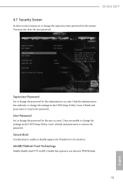
H110M-HDV 4.7 Security Screen In this section you may also clear the user password. Leave it blank and press enter to change the password for the system. Secure Boot Use this option to change the settings in the UEFI Setup Utility. Supervisor Password Set or change the supervisor/user password for the user account. User Password Set or change the settings in ME. Only the administrator has authority to remove the password. Disable this item to remove the password. Intel(R) Platform Trust Technology Enable/disable Intel PTT...
H110M-HDV 4.7 Security Screen In this section you may also clear the user password. Leave it blank and press enter to change the password for the system. Secure Boot Use this option to change the settings in the UEFI Setup Utility. Supervisor Password Set or change the supervisor/user password for the user account. User Password Set or change the settings in ME. Only the administrator has authority to remove the password. Disable this item to remove the password. Intel(R) Platform Trust Technology Enable/disable Intel PTT...


