User Manual
Page 2
...BMP) regulations passed by any interference received, including interference that may appear in this documentation. Copyright Notice: No part of ASRock Inc. Disclaimer: Specifications and information contained in this documentation may be reproduced, transcribed, transmitted, or translated in any language...notice, and should not be constructed as a commitment by the purchaser for a particular purpose. All rights reserved. ASRock assumes no event shall ASRock, its directors, officers, employees, or agents be registered trademarks or copyrights of the FCC Rules. When you ...
...BMP) regulations passed by any interference received, including interference that may appear in this documentation. Copyright Notice: No part of ASRock Inc. Disclaimer: Specifications and information contained in this documentation may be reproduced, transcribed, transmitted, or translated in any language...notice, and should not be constructed as a commitment by the purchaser for a particular purpose. All rights reserved. ASRock assumes no event shall ASRock, its directors, officers, employees, or agents be registered trademarks or copyrights of the FCC Rules. When you ...

User Manual
Page 3
The terms HDMI™ and HDMI High-Definition Multimedia Interface, and the HDMI logo are trademarks or registered trademarks of HDMI Licensing LLC in the United States and other countries.
The terms HDMI™ and HDMI High-Definition Multimedia Interface, and the HDMI logo are trademarks or registered trademarks of HDMI Licensing LLC in the United States and other countries.
User Manual
Page 4
... (DIMM) 15 2.4 Expansion Slots (PCI Express Slots) 17 2.5 Jumpers Setup 18 2.6 Onboard Headers and Connectors 19 Chapter 3 Software and Utilities Operation 23 3.1 Installing Drivers 23 3.2 ASRock Live Update & APP Shop 24 3.2.1 UI Overview 24 3.2.2 Apps 25 3.2.3 BIOS & Drivers 28 3.2.4 Setting 29 3.3 Enabling USB Ports for Windows® 7 Installation 30 Chapter 4 UEFI...
... (DIMM) 15 2.4 Expansion Slots (PCI Express Slots) 17 2.5 Jumpers Setup 18 2.6 Onboard Headers and Connectors 19 Chapter 3 Software and Utilities Operation 23 3.1 Installing Drivers 23 3.2 ASRock Live Update & APP Shop 24 3.2.1 UI Overview 24 3.2.2 Apps 25 3.2.3 BIOS & Drivers 28 3.2.4 Setting 29 3.3 Enabling USB Ports for Windows® 7 Installation 30 Chapter 4 UEFI...
User Manual
Page 5
4.1.1 UEFI Menu Bar 33 4.1.2 Navigation Keys 34 4.2 Main Screen 35 4.3 OC Tweaker Screen 36 4.4 Advanced Screen 44 4.4.1 CPU Configuration 45 4.4.2 Chipset Configuration 47 4.4.3 Storage Configuration 49 4.4.4 Super IO Configuration 50 4.4.5 ACPI Configuration 51 4.4.6 USB Configuration 53 4.4.7 Trusted Computing 54 4.5 Tools 55 4.6 Hardware Health Event Monitoring Screen 59 4.7 Security Screen 61 4.8 Boot Screen 62 4.9 Exit Screen 65
4.1.1 UEFI Menu Bar 33 4.1.2 Navigation Keys 34 4.2 Main Screen 35 4.3 OC Tweaker Screen 36 4.4 Advanced Screen 44 4.4.1 CPU Configuration 45 4.4.2 Chipset Configuration 47 4.4.3 Storage Configuration 49 4.4.4 Super IO Configuration 50 4.4.5 ACPI Configuration 51 4.4.6 USB Configuration 53 4.4.7 Trusted Computing 54 4.5 Tools 55 4.6 Hardware Health Event Monitoring Screen 59 4.7 Security Screen 61 4.8 Boot Screen 62 4.9 Exit Screen 65
User Manual
Page 6
... the motherboard specifications and the BIOS software might be available on ASRock's website as well. Chapter 3 contains the operation guide of the BIOS setup. ASRock website http://www.asrock.com. 1.1 Package Contents • ASRock H110M-HDV Motherboard (Micro ATX Form Factor) • ASRock H110M-HDV Quick Installation Guide • ASRock H110M-HDV Support CD • 2 x Serial ATA (SATA) Data Cables (Optional) •...
... the motherboard specifications and the BIOS software might be available on ASRock's website as well. Chapter 3 contains the operation guide of the BIOS setup. ASRock website http://www.asrock.com. 1.1 Package Contents • ASRock H110M-HDV Motherboard (Micro ATX Form Factor) • ASRock H110M-HDV Quick Installation Guide • ASRock H110M-HDV Support CD • 2 x Serial ATA (SATA) Data Cables (Optional) •...
User Manual
Page 7
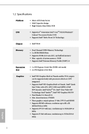
resolution up to 1920x1200 @ 60Hz • Supports D-Sub with AVC, MVC (S3D) and MPEG-2 Full HW Encode1, Intel® InTruTM 3D, Intel® Clear Video HD Technology, Intel® InsiderTM, Intel® HD Graphics 510/530 • Pixel Shader 5.0, DirectX 12 • Max. capacity of system memory: 32GB • Supports Intel® Extreme Memory Profile (XMP) 2.0 Expansion Slot • 1 x PCI Express 3.0 x16 Slot (PCIE1: x16 mode) • 2 x PCI Express 2.0 x1 Slots Graphics • Intel® HD Graphics Built-in Visuals and the VGA outputs can be supported only with processors which...
resolution up to 1920x1200 @ 60Hz • Supports D-Sub with AVC, MVC (S3D) and MPEG-2 Full HW Encode1, Intel® InTruTM 3D, Intel® Clear Video HD Technology, Intel® InsiderTM, Intel® HD Graphics 510/530 • Pixel Shader 5.0, DirectX 12 • Max. capacity of system memory: 32GB • Supports Intel® Extreme Memory Profile (XMP) 2.0 Expansion Slot • 1 x PCI Express 3.0 x16 Slot (PCIE1: x16 mode) • 2 x PCI Express 2.0 x1 Slots Graphics • Intel® HD Graphics Built-in Visuals and the VGA outputs can be supported only with processors which...
User Manual
Page 8
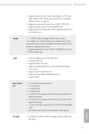
H110M-HDV • Supports Auto Lip Sync, Deep Color (12bpc), xvYCC and HBR (High ...front panel audio module and enable the multi-channel audio feature through the audio driver. • Supports Surge Protection (ASRock Full Spike Protection) • ELNA Audio Caps LAN • PCIE x1 Gigabit LAN 10/100/1000 Mb/s &#...8226; Realtek RTL8111E • Supports Wake-On-LAN • Supports Lightning/ESD Protection (ASRock Full Spike Protection) • Supports LAN Cable Detection • Supports Energy Efficient Ethernet 802.3az • Supports PXE Rear Panel ...
H110M-HDV • Supports Auto Lip Sync, Deep Color (12bpc), xvYCC and HBR (High ...front panel audio module and enable the multi-channel audio feature through the audio driver. • Supports Surge Protection (ASRock Full Spike Protection) • ELNA Audio Caps LAN • PCIE x1 Gigabit LAN 10/100/1000 Mb/s &#...8226; Realtek RTL8111E • Supports Wake-On-LAN • Supports Lightning/ESD Protection (ASRock Full Spike Protection) • Supports LAN Cable Detection • Supports Energy Efficient Ethernet 802.3az • Supports PXE Rear Panel ...
User Manual
Page 9
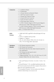
...Panel Audio Connector • 2 x USB 2.0 Headers (Support 4 USB 2.0 ports) (Supports ESD Protection (ASRock Full Spike Protection)) • 1 x USB 3.0 Header (Supports 2 USB 3.0 ports) (Supports ESD Protection (ASRock Full Spike Protection)) * USB3_4_5 is required. CPLL, VCCSA Voltage Multi-adjustment Hardware Monitor • CPU/Chassis ...to page 30 for more detailed instructions. * For the updated Windows® 10 driver, please visit ASRock's website for details: http://www.asrock.com English 4 bit * To install Windows® 7 OS, a modified installation disk with xHCI...
...Panel Audio Connector • 2 x USB 2.0 Headers (Support 4 USB 2.0 ports) (Supports ESD Protection (ASRock Full Spike Protection)) • 1 x USB 3.0 Header (Supports 2 USB 3.0 ports) (Supports ESD Protection (ASRock Full Spike Protection)) * USB3_4_5 is required. CPLL, VCCSA Voltage Multi-adjustment Hardware Monitor • CPU/Chassis ...to page 30 for more detailed instructions. * For the updated Windows® 10 driver, please visit ASRock's website for details: http://www.asrock.com English 4 bit * To install Windows® 7 OS, a modified installation disk with xHCI...
User Manual
Page 10
... and expense. We are not responsible for possible damage caused by overclocking. H110M-HDV Certifications • FCC, CE, WHQL • ErP/EuP Ready (ErP/EuP ready power supply is required) * For detailed product information, please visit our website: http://www.asrock.com Please realize that there is a certain risk involved with overclocking, including...
... and expense. We are not responsible for possible damage caused by overclocking. H110M-HDV Certifications • FCC, CE, WHQL • ErP/EuP Ready (ErP/EuP ready power supply is required) * For detailed product information, please visit our website: http://www.asrock.com Please realize that there is a certain risk involved with overclocking, including...
User Manual
Page 11
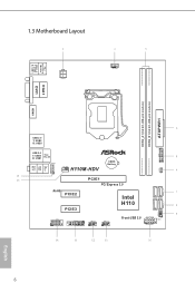
1.3 Motherboard Layout PS2 Keyboard /Mouse USB 3.0 T: USB0 B: USB1 ATX12V1 CPU_FAN1 VGA1 DVI1 ATXPWR1 DDR4_A1 (64 bit, 288-pin module) DDR4_B1 (64 bit, 288-pin module) HDMI1 SATA3_2_3 SPK_CI1 SATA3_4_5 Top: LINE IN Center: FRONT Bottom: MIC IN USB 2.0 T: USB2 B: USB3 1 TPMS1 USB 2.0 T: USB0 Top: B: USB1 RJ-45 HD_AUDIO1 CHA_FAN1 H110M-HDV CMOS Battery CLRMOS1 1 1 PCIE1 PCI Express 3.0 RoHS PCIE2 PCIE3 Intel H110 COM1 1 USB3_4_5 USB_6_7 1 1 USB_4_5 1 Front USB 3.0 PLED PWRBTN 1 HDLED RESET 1 PANEL1 6 English
1.3 Motherboard Layout PS2 Keyboard /Mouse USB 3.0 T: USB0 B: USB1 ATX12V1 CPU_FAN1 VGA1 DVI1 ATXPWR1 DDR4_A1 (64 bit, 288-pin module) DDR4_B1 (64 bit, 288-pin module) HDMI1 SATA3_2_3 SPK_CI1 SATA3_4_5 Top: LINE IN Center: FRONT Bottom: MIC IN USB 2.0 T: USB2 B: USB3 1 TPMS1 USB 2.0 T: USB0 Top: B: USB1 RJ-45 HD_AUDIO1 CHA_FAN1 H110M-HDV CMOS Battery CLRMOS1 1 1 PCIE1 PCI Express 3.0 RoHS PCIE2 PCIE3 Intel H110 COM1 1 USB3_4_5 USB_6_7 1 1 USB_4_5 1 Front USB 3.0 PLED PWRBTN 1 HDLED RESET 1 PANEL1 6 English
User Manual
Page 12
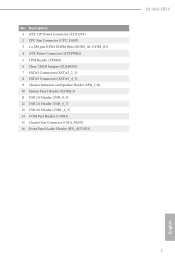
Description 1 ATX 12V Power Connector (ATX12V1) 2 CPU Fan Connector (CPU_FAN1) 3 2 x 288-pin DDR4 DIMM Slots (DDR4_A1, DDR4_B1) 4 ATX Power Connector (ATXPWR1) 5 TPM Header (TPMS1) 6 Clear CMOS Jumper (CLRMOS1) 7 SATA3 Connectors (SATA3_2_3) 8 SATA3 Connectors (SATA3_4_5) 9 Chassis Intrusion and Speaker Header (SPK_CI1) 10 System Panel Header (PANEL1) 11 USB 2.0 Header (USB_4_5) 12 USB 2.0 Header (USB_6_7) 13 USB 3.0 Header (USB3_4_5) 14 COM Port Header (COM1) 15 Chassis Fan Connector (CHA_FAN1) 16 Front Panel Audio Header (HD_AUDIO1) H110M-HDV English 7 No.
Description 1 ATX 12V Power Connector (ATX12V1) 2 CPU Fan Connector (CPU_FAN1) 3 2 x 288-pin DDR4 DIMM Slots (DDR4_A1, DDR4_B1) 4 ATX Power Connector (ATXPWR1) 5 TPM Header (TPMS1) 6 Clear CMOS Jumper (CLRMOS1) 7 SATA3 Connectors (SATA3_2_3) 8 SATA3 Connectors (SATA3_4_5) 9 Chassis Intrusion and Speaker Header (SPK_CI1) 10 System Panel Header (PANEL1) 11 USB 2.0 Header (USB_4_5) 12 USB 2.0 Header (USB_6_7) 13 USB 3.0 Header (USB3_4_5) 14 COM Port Header (COM1) 15 Chassis Fan Connector (CHA_FAN1) 16 Front Panel Audio Header (HD_AUDIO1) H110M-HDV English 7 No.

User Manual
Page 13
Please refer to the table below for the LAN port LED indications. 1.4 I/O Panel 1 2 4 3 5 11 10 9 8 7 6 No. ACT/LINK LED SPEED LED LAN Port Activity / Link LED Status Description Off Blinking On No Link Data Activity Link Speed LED Status Off Orange Green Description 10Mbps connection 100Mbps connection 1Gbps connection English 8 Description 7 USB 2.0 Ports (USB01) 8 USB 2.0 Ports (USB_23) 9 HDMI Port 10 DVI-D Port 11 USB 3.0 Ports (USB3_01) * There are two LEDs on the LAN port. Description 1 PS/2 Mouse/Keyboard Port 2 D-Sub Port 3 LAN RJ-45 Port* 4 Line In (Light ...
Please refer to the table below for the LAN port LED indications. 1.4 I/O Panel 1 2 4 3 5 11 10 9 8 7 6 No. ACT/LINK LED SPEED LED LAN Port Activity / Link LED Status Description Off Blinking On No Link Data Activity Link Speed LED Status Off Orange Green Description 10Mbps connection 100Mbps connection 1Gbps connection English 8 Description 7 USB 2.0 Ports (USB01) 8 USB 2.0 Ports (USB_23) 9 HDMI Port 10 DVI-D Port 11 USB 3.0 Ports (USB3_01) * There are two LEDs on the LAN port. Description 1 PS/2 Mouse/Keyboard Port 2 D-Sub Port 3 LAN RJ-45 Port* 4 Line In (Light ...
User Manual
Page 14
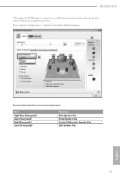
Function of the Audio Ports in the Realtek HD Audio Manager. Please set Speaker Configuration to use an HD front panel audio module and enable the multichannel audio feature through the audio driver. H110M-HDV ** To configure 7.1 CH HD Audio, it is required to "7.1 Speaker"in 7.1-channel Configuration: Port Light Blue (Rear panel) Lime (Rear panel) Pink (Rear panel) Lime (Front panel) Function Rear Speaker Out Front Speaker Out Central /Subwoofer Speaker Out Side Speaker Out 9 English
Function of the Audio Ports in the Realtek HD Audio Manager. Please set Speaker Configuration to use an HD front panel audio module and enable the multichannel audio feature through the audio driver. H110M-HDV ** To configure 7.1 CH HD Audio, it is required to "7.1 Speaker"in 7.1-channel Configuration: Port Light Blue (Rear panel) Lime (Rear panel) Pink (Rear panel) Lime (Front panel) Function Rear Speaker Out Front Speaker Out Central /Subwoofer Speaker Out Side Speaker Out 9 English
User Manual
Page 15
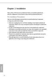
Chapter 2 Installation This is a Micro ATX form factor motherboard. Pre-installation Precautions Take note of your motherboard directly on a grounded anti-static pad or in the bag that the motherboard fits into it. Also remember to unplug the power cord before you handle the components. • Hold components by the edges and do not touch the ICs. • Whenever you install motherboard components or change any components, place them on a carpet. Before you install the motherboard, study the configuration of the following precautions before you uninstall any motherboard ...
Chapter 2 Installation This is a Micro ATX form factor motherboard. Pre-installation Precautions Take note of your motherboard directly on a grounded anti-static pad or in the bag that the motherboard fits into it. Also remember to unplug the power cord before you handle the components. • Hold components by the edges and do not touch the ICs. • Whenever you install motherboard components or change any components, place them on a carpet. Before you install the motherboard, study the configuration of the following precautions before you uninstall any motherboard ...
User Manual
Page 16
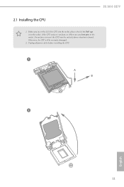
Unplug all power cables before installing the CPU. 1 A B 2 11 English Otherwise, the CPU will be seriously damaged. 2. H110M-HDV 2.1 Installing the CPU 1. Before you insert the 1151-Pin CPU into the socket if above situation is unclean, or if there are any bent pins in the socket. Do not force to insert the CPU into the socket, please check if the PnP cap is on the socket, if the CPU surface is found.
Unplug all power cables before installing the CPU. 1 A B 2 11 English Otherwise, the CPU will be seriously damaged. 2. H110M-HDV 2.1 Installing the CPU 1. Before you insert the 1151-Pin CPU into the socket if above situation is unclean, or if there are any bent pins in the socket. Do not force to insert the CPU into the socket, please check if the PnP cap is on the socket, if the CPU surface is found.
User Manual
Page 18
The cover must be placed if you wish to return the motherboard for after service. 13 English H110M-HDV Please save and replace the cover if the processor is removed.
The cover must be placed if you wish to return the motherboard for after service. 13 English H110M-HDV Please save and replace the cover if the processor is removed.
User Manual
Page 19
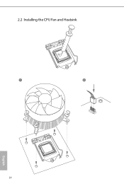
2.2 Installing the CPU Fan and Heatsink 1 2 CPU_FAN English 14
2.2 Installing the CPU Fan and Heatsink 1 2 CPU_FAN English 14
User Manual
Page 20
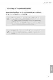
H110M-HDV 2.3 Installing Memory Modules (DIMM) This motherboard provides two 288-pin DDR4 (Double Data Rate 4) DIMM slots, and supports Dual Channel Memory Technology. 1. For dual channel ...
H110M-HDV 2.3 Installing Memory Modules (DIMM) This motherboard provides two 288-pin DDR4 (Double Data Rate 4) DIMM slots, and supports Dual Channel Memory Technology. 1. For dual channel ...
User Manual
Page 22
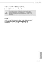
H110M-HDV 2.4 Expansion Slots (PCI Express Slots) There are 3 PCI Express slots on the motherboard. Please read the documentation of the expansion card and make sure that ...
H110M-HDV 2.4 Expansion Slots (PCI Express Slots) There are 3 PCI Express slots on the motherboard. Please read the documentation of the expansion card and make sure that ...
User Manual
Page 23
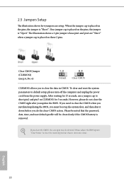
If no jumper cap is placed on CLRMOS1 for 15 seconds, use a jumper cap to clear the data in CMOS. However, please do the clear-CMOS action. Please be noted that the password, date, time, and user default profile will be detected. After waiting for 5 seconds. Clear CMOS Jumper (CLRMOS1) (see p.6, No. 6) Default Clear CMOS CLRMOS1 allows you update the BIOS. The illustration shows a 3-pin jumper whose pin1 and pin2 are setup. To clear and reset the system parameters to clear the record of previous chassis intrusion status. If you clear the CMOS, the case open ...
If no jumper cap is placed on CLRMOS1 for 15 seconds, use a jumper cap to clear the data in CMOS. However, please do the clear-CMOS action. Please be noted that the password, date, time, and user default profile will be detected. After waiting for 5 seconds. Clear CMOS Jumper (CLRMOS1) (see p.6, No. 6) Default Clear CMOS CLRMOS1 allows you update the BIOS. The illustration shows a 3-pin jumper whose pin1 and pin2 are setup. To clear and reset the system parameters to clear the record of previous chassis intrusion status. If you clear the CMOS, the case open ...