RAID Installation Guide
Page 2
... data cable to the SATA hard disk. 2 STEP 2: Connect the SATA power cable to SATA Hard Disks Installation 1.1 Serial ATA (SATA) Hard Disks Installation This motherboard adopts VIA VT8237 southbridge chipset that supports Serial ATA (SATA) hard disks. STEP 4: Connect the other end of your chassis. STEP 3: Connect one end of... the SATA data cable to install the SATA hard disks. This section will guide you to the motherboard's SATA connector. 1. You may install SATA hard disks on this...
... data cable to the SATA hard disk. 2 STEP 2: Connect the SATA power cable to SATA Hard Disks Installation 1.1 Serial ATA (SATA) Hard Disks Installation This motherboard adopts VIA VT8237 southbridge chipset that supports Serial ATA (SATA) hard disks. STEP 4: Connect the other end of your chassis. STEP 3: Connect one end of... the SATA data cable to install the SATA hard disks. This section will guide you to the motherboard's SATA connector. 1. You may install SATA hard disks on this...
RAID Installation Guide
Page 4
... guide to RAID Configurations 2.1 Introduction of the same model and capacity when creating a RAID set. For optimal performance, please install identical drives of RAID This motherboard adopts VIA VT8237 south bridge chipset that optimizes two identical hard disk drives to read and write data in parallel, interleaved stacks.
... guide to RAID Configurations 2.1 Introduction of the same model and capacity when creating a RAID set. For optimal performance, please install identical drives of RAID This motherboard adopts VIA VT8237 south bridge chipset that optimizes two identical hard disk drives to read and write data in parallel, interleaved stacks.
User Manual
Page 3
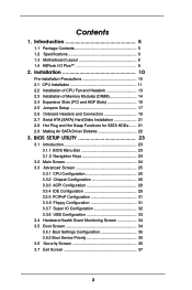
... (SATA) Hard Disks Installation 21 2.8 Hot Plug and Hot Swap Functions for SATA HDDs ....... 21 2.9 Making An SATA Driver Diskette 22 3. Introduction 5 1.1 Package Contents 5 1.2 Specifications 6 1.3 Motherboard Layout 8 1.4 ASRock I/O Plus 9 TM 2.
... (SATA) Hard Disks Installation 21 2.8 Hot Plug and Hot Swap Functions for SATA HDDs ....... 21 2.9 Making An SATA Driver Diskette 22 3. Introduction 5 1.1 Package Contents 5 1.2 Specifications 6 1.3 Motherboard Layout 8 1.4 ASRock I/O Plus 9 TM 2.
User Manual
Page 5
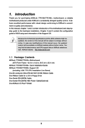
... 2 contain introduction of this manual occur, the updated version will be subject to quality and endurance. ASRock website http://www.asrock.com 1.1 Package Contents ASRock 775V88/775V88+ Motherboard (ATX Form Factor: 12.0-in x 9.2-in, 30.5 cm x 23.4 cm) ASRock 775V88/775V88+ Quick Installation Guide ASRock 775V88/775V88+ Support CD (including LGA 775 CPU Installation Live Demo) One 80-conductor Ultra ATA 66...
... 2 contain introduction of this manual occur, the updated version will be subject to quality and endurance. ASRock website http://www.asrock.com 1.1 Package Contents ASRock 775V88/775V88+ Motherboard (ATX Form Factor: 12.0-in x 9.2-in, 30.5 cm x 23.4 cm) ASRock 775V88/775V88+ Quick Installation Guide ASRock 775V88/775V88+ Support CD (including LGA 775 CPU Installation Live Demo) One 80-conductor Ultra ATA 66...
User Manual
Page 7
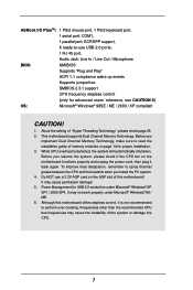
...is not recommended to perform over-clocking. It may cause the instability of the system or damage the CPU. 7 Although this motherboard! Frequencies other than the recommended CPU bus frequencies may cause permanent damage! 5. Before you implement Dual Channel Memory Technology, make...98 / ME. 6. Power Management for advanced users' reference, see CAUTION 6) OS: Microsoft® Windows® 98SE / ME / 2000 / XP compliant CAUTION! 1. ASRock I/O PlusTM: 1 PS/2 mouse port, 1 PS/2 keyboard port, 1 serial port: COM1, 1 parallel port: ECP/EPP support, 6 ready-to-use a 3.3V...
...is not recommended to perform over-clocking. It may cause the instability of the system or damage the CPU. 7 Although this motherboard! Frequencies other than the recommended CPU bus frequencies may cause permanent damage! 5. Before you implement Dual Channel Memory Technology, make...98 / ME. 6. Power Management for advanced users' reference, see CAUTION 6) OS: Microsoft® Windows® 98SE / ME / 2000 / XP compliant CAUTION! 1. ASRock I/O PlusTM: 1 PS/2 mouse port, 1 PS/2 keyboard port, 1 serial port: COM1, 1 parallel port: ECP/EPP support, 6 ready-to-use a 3.3V...
User Manual
Page 8
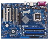
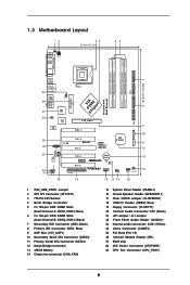
1.3 Motherboard Layout 12 PS2 Mouse 1 PS2_USB_PWR1 ATX12V1 Ps2 Keyboard PARALLEL PORT COM1 34 23.4cm (9.2 in) 56 DDR3 (64/72 bit, 184-pin module) DDR4 (64/... GAME1 PCI 3 USB2.0 AGP 8X VIA VT8237 AUX1 CD1 23 Audio CODEC AUDIO1 22 21 1 JR1 JL1 PCI 4 FSB800 DDR400 CMOS Battery PCI 5 CLRCMOS1 FLOPPY1 775V88+ 1 USB67 1 SPEAKER1 PLED PWRBTN 1 HDLED RESET PANEL 1 CHA_FAN1 20 19 18 17 16 15 30.5cm (12.0in) 7 8 9 10 11 12 13 14 1 PS2_USB_PWR1 Jumper...
1.3 Motherboard Layout 12 PS2 Mouse 1 PS2_USB_PWR1 ATX12V1 Ps2 Keyboard PARALLEL PORT COM1 34 23.4cm (9.2 in) 56 DDR3 (64/72 bit, 184-pin module) DDR4 (64/... GAME1 PCI 3 USB2.0 AGP 8X VIA VT8237 AUX1 CD1 23 Audio CODEC AUDIO1 22 21 1 JR1 JL1 PCI 4 FSB800 DDR400 CMOS Battery PCI 5 CLRCMOS1 FLOPPY1 775V88+ 1 USB67 1 SPEAKER1 PLED PWRBTN 1 HDLED RESET PANEL 1 CHA_FAN1 20 19 18 17 16 15 30.5cm (12.0in) 7 8 9 10 11 12 13 14 1 PS2_USB_PWR1 Jumper...

User Manual
Page 10
... component. Whenever you uninstall any component. 2. Before you install or remove any motherboard settings. 1. Before you install the motherboard, study the configuration of the following precautions before you handle components. 3. Installation 775V88/775V88+ is detached from the wall socket before you install motherboard components or change any component, ensure that the power is switched off...
... component. Whenever you uninstall any component. 2. Before you install or remove any motherboard settings. 1. Before you install the motherboard, study the configuration of the following precautions before you handle components. 3. Installation 775V88/775V88+ is detached from the wall socket before you install motherboard components or change any component, ensure that the power is switched off...
User Manual
Page 13
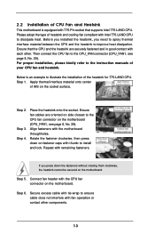
...securely fastened and in good contact with thumb to improve heat dissipation. Repeat with Intel 775-LAND CPU to the CPU fan connector on the motherboard (CPU_FAN1, see page 8, No. 29). For proper installation, please kindly refer to illustrate the installation of your CPU fan and heatsink. ...Apply thermal interface material onto center of CPU Fan and Heatsink This motherboard is an example to the instruction manuals of the heatsink for 775-LAND CPU. Place the heatsink onto the socket. Step 5. Before you...
...securely fastened and in good contact with thumb to improve heat dissipation. Repeat with Intel 775-LAND CPU to the CPU fan connector on the motherboard (CPU_FAN1, see page 8, No. 29). For proper installation, please kindly refer to illustrate the installation of your CPU fan and heatsink. ...Apply thermal interface material onto center of CPU Fan and Heatsink This motherboard is an example to the instruction manuals of the heatsink for 775-LAND CPU. Place the heatsink onto the socket. Step 5. Before you...
User Manual
Page 14
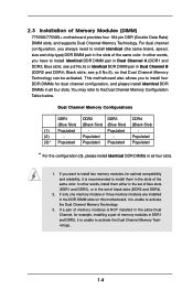
... to install four DDR DIMMs for dual channel configuration, and please install identical DDR DIMMs in the slots of Memory Modules (DIMM) 775V88/775V88+ motherboard provides four 184-pin DDR (Double Data Rate) DIMM slots, and supports Dual Channel Memory Technology. see p.8 No.6), so that Dual... Memory Technology can be activated. If only one memory module or three memory modules are installed in the DDR DIMM slots on this motherboard, it is unable to the Dual Channel Memory Configuration Table below. Blue slots; Populated (3)* Populated Populated Populated Populated * For the ...
... to install four DDR DIMMs for dual channel configuration, and please install identical DDR DIMMs in the slots of Memory Modules (DIMM) 775V88/775V88+ motherboard provides four 184-pin DDR (Double Data Rate) DIMM slots, and supports Dual Channel Memory Technology. see p.8 No.6), so that Dual... Memory Technology can be activated. If only one memory module or three memory modules are installed in the DDR DIMM slots on this motherboard, it is unable to the Dual Channel Memory Configuration Table below. Blue slots; Populated (3)* Populated Populated Populated Populated * For the ...

User Manual
Page 15
... components. Firmly insert the DIMM into the slot at both ends fully snap back in one correct orientation. Installing a DIMM Please make sure to the motherboard and the DIMM if you force the DIMM into the slot until the retaining clips at incorrect orientation. notch break notch break The DIMM only...
... components. Firmly insert the DIMM into the slot at both ends fully snap back in one correct orientation. Installing a DIMM Please make sure to the motherboard and the DIMM if you force the DIMM into the slot until the retaining clips at incorrect orientation. notch break notch break The DIMM only...
User Manual
Page 16
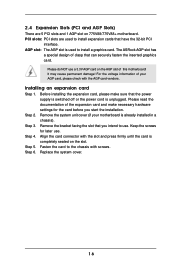
... is unplugged. The ASRock AGP slot has a special design of clasp that the power supply is switched off or the power cord is completely seated on the slot. Step 3. Keep the screws for the card before you intend to use a 3.3V AGP card on 775V88/775V88+ motherboard. Align the card... check with the AGP card vendors. Step 5. AGP slot: The AGP slot is already installed in a chassis). For the voltage information of your motherboard is used to install expansion cards that you start the installation. Step 4. Please do NOT use . Step 2. Step 6. Remove the bracket facing the...
... is unplugged. The ASRock AGP slot has a special design of clasp that the power supply is switched off or the power cord is completely seated on the slot. Step 3. Keep the screws for the card before you intend to use a 3.3V AGP card on 775V88/775V88+ motherboard. Align the card... check with the AGP card vendors. Step 5. AGP slot: The AGP slot is already installed in a chassis). For the voltage information of your motherboard is used to install expansion cards that you start the installation. Step 4. Please do NOT use . Step 2. Step 6. Remove the bracket facing the...
User Manual
Page 18
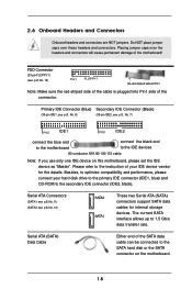
... (33-pin FLOPPY1) (see p.8, No. 19) Pin1 FLOPPY1 the red-striped side to the SATA hard disk or the SATA connector on this motherboard, please set the IDE device as "Master". Serial ATA (SATA) Data Cable Either end of the SATA data cable can be connected to Pin1 ...Note: Make sure the red-striped side of the cable is plugged into Pin1 side of the motherboard! Besides, to optimize compatibility and performance, please connect your IDE device vendor for internal storage devices. Placing jumper caps over these headers and connectors....
... (33-pin FLOPPY1) (see p.8, No. 19) Pin1 FLOPPY1 the red-striped side to the SATA hard disk or the SATA connector on this motherboard, please set the IDE device as "Master". Serial ATA (SATA) Data Cable Either end of the SATA data cable can be connected to Pin1 ...Note: Make sure the red-striped side of the cable is plugged into Pin1 side of the motherboard! Besides, to optimize compatibility and performance, please connect your IDE device vendor for internal storage devices. Placing jumper caps over these headers and connectors....
User Manual
Page 21
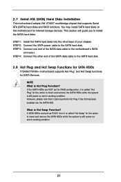
... into the drive bays of the SATA data cable to the SATA hard disk. 2.8 Hot Plug and Hot Swap Functions for SATA HDDs 775V88/775V88+ motherboard supports Hot Plug and Hot Swap functions for the action to insert and remove the SATA HDDs while the system is still power-on and... Function? STEP 1: Install the SATA hard disks into the SATA HDD. What is Hot Plug Function? 2.7 Serial ATA (SATA) Hard Disks Installation This motherboard adopts VIA VT8237 southbridge chipset that it is called "Hot Plug" for internal storage devices. STEP 3: Connect one end of the SATA data cable to...
... into the drive bays of the SATA data cable to the SATA hard disk. 2.8 Hot Plug and Hot Swap Functions for SATA HDDs 775V88/775V88+ motherboard supports Hot Plug and Hot Swap functions for the action to insert and remove the SATA HDDs while the system is still power-on and... Function? STEP 1: Install the SATA hard disks into the SATA HDD. What is Hot Plug Function? 2.7 Serial ATA (SATA) Hard Disks Installation This motherboard adopts VIA VT8237 southbridge chipset that it is called "Hot Plug" for internal storage devices. STEP 3: Connect one end of the SATA data cable to...

User Manual
Page 23
... on the system chassis. If you wish to get into the sub screen. 23 You may also restart by pressing the reset button on the motherboard stores the BIOS SETUP UTILITY. You may run the BIOS SETUP UTILITY when you see on . Because the BIOS software is constantly being updated, the...
... on the system chassis. If you wish to get into the sub screen. 23 You may also restart by pressing the reset button on the motherboard stores the BIOS SETUP UTILITY. You may run the BIOS SETUP UTILITY when you see on . Because the BIOS software is constantly being updated, the...
User Manual
Page 25
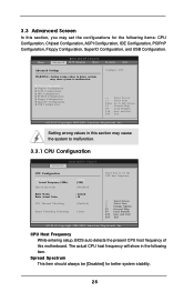
..., PCIPnP Configuration, Floppy Configuration, SuperIO Configuration, and USB Configuration. CPU Host Frequency While entering setup, BIOS auto detects the present CPU host frequency of this motherboard. CPU Configuration Chipset Configuration ACPI Configuration IDE Configuration PCIPnP Configuration Floppy Configuration SuperIO Configuration USB Configuration Configure CPU Select Screen Select Item Enter Go to...
..., PCIPnP Configuration, Floppy Configuration, SuperIO Configuration, and USB Configuration. CPU Host Frequency While entering setup, BIOS auto detects the present CPU host frequency of this motherboard. CPU Configuration Chipset Configuration ACPI Configuration IDE Configuration PCIPnP Configuration Floppy Configuration SuperIO Configuration USB Configuration Configure CPU Select Screen Select Item Enter Go to...
User Manual
Page 26
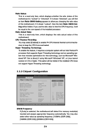
...Microsoft® Windows® XP. Ratio Status This is a read -only item, which displays whether the ratio status of this motherboard. If it requires a computer system with an Intel Pentium®4 processor that supports Hyper-Threading technology and an operating system that includes...CPU from overheated. This option will detect the memory module(s) inserted and assigns appropriate frequency automatically. Ratio Actual Value This is selected, the motherboard will be hidden. DRAM Frequency If [Auto] is a read -only item, which displays the ratio actual value of this technology, ...
...Microsoft® Windows® XP. Ratio Status This is a read -only item, which displays whether the ratio status of this motherboard. If it requires a computer system with an Intel Pentium®4 processor that supports Hyper-Threading technology and an operating system that includes...CPU from overheated. This option will detect the memory module(s) inserted and assigns appropriate frequency automatically. Ratio Actual Value This is selected, the motherboard will be hidden. DRAM Frequency If [Auto] is a read -only item, which displays the ratio actual value of this technology, ...
User Manual
Page 27
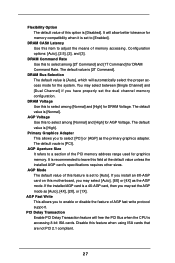
... may select [Auto], [8X] or [4X] as the AGP mode. The default vaule is [2T Command]. If you install an 8X-AGP card on this motherboard, you may select between [Single Channel] and [Dual Channel] if you to select [PCI] or [AGP] as [Auto], [4X], [2X], or [1X]. The default value...
... may select [Auto], [8X] or [4X] as the AGP mode. The default vaule is [2T Command]. If you install an 8X-AGP card on this motherboard, you may select between [Single Channel] and [Dual Channel] if you to select [PCI] or [AGP] as [Auto], [4X], [2X], or [1X]. The default value...

User Manual
Page 34
... Monitoring Screen In this section, it allows you to monitor the status of the hardware on your system, including the parameters of the CPU temperature, motherboard temperature, CPU fan speed, chassis fan speed, and the critical voltage. Main Advanced BIOS SETUP UTILITY H/W Monitor Boot Security Exit Boot Settings Boot Settings Configuration...
... Monitoring Screen In this section, it allows you to monitor the status of the hardware on your system, including the parameters of the CPU temperature, motherboard temperature, CPU fan speed, chassis fan speed, and the critical voltage. Main Advanced BIOS SETUP UTILITY H/W Monitor Boot Security Exit Boot Settings Boot Settings Configuration...
User Manual
Page 38
... system detects installed devices. You may find this Live Demo in the motherboard's Support CD through this Live Demo, you need to contact ASRock or want to your CD-ROM drive. Because motherboard settings and hardware options vary, use the setup procedures in the Support ...the file "ASSETUP.EXE" from the BIN folder in this live demo program before you start the installation of CPU and motherboard damages caused by improper handling, ASRock sincerely presents you a clear installation guide through the following path: ..\ MPEGAV \ LGA775INST.DAT 4.2.5 Contact Information If you can...
... system detects installed devices. You may find this Live Demo in the motherboard's Support CD through this Live Demo, you need to contact ASRock or want to your CD-ROM drive. Because motherboard settings and hardware options vary, use the setup procedures in the Support ...the file "ASSETUP.EXE" from the BIN folder in this live demo program before you start the installation of CPU and motherboard damages caused by improper handling, ASRock sincerely presents you a clear installation guide through the following path: ..\ MPEGAV \ LGA775INST.DAT 4.2.5 Contact Information If you can...
Quick Installation Guide
Page 1
... accept any interference received, including interference that may not be registered trademarks or copyrights of the FCC Rules. ASRock Website: http://www.asrock.com Published April 2005 Copyright©2005 ASRock INC. All rights reserved. 1 ASRock 775V88/775V88+ Motherboard English Copyright Notice: No part of this installation guide may be liable for any indirect, special, incidental, or...
... accept any interference received, including interference that may not be registered trademarks or copyrights of the FCC Rules. ASRock Website: http://www.asrock.com Published April 2005 Copyright©2005 ASRock INC. All rights reserved. 1 ASRock 775V88/775V88+ Motherboard English Copyright Notice: No part of this installation guide may be liable for any indirect, special, incidental, or...


