RAID Installation Guide
Page 1
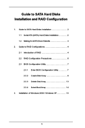
Guide to SATA Hard Disks Installation 2 1.1 Serial ATA (SATA) Hard Disks Installation 2 1.2 Making An SATA Driver Diskette 3 2. Installation of RAID 4 2.2 RAID Configuration Precautions 6 2.3 BIOS Configuration Utility 7 2.3.1 Enter BIOS Configuration Utility 7 2.3.2 Create Disk Array 8 2.3.3 Delete Disk Array 13 2.3.4 Select Boot Array 14 3. Guide to RAID Configurations 4 2.1 Introduction of Windows 2000 / Windows XP 15 1 Guide to SATA Hard Disks Installation and RAID Configuration 1.
Guide to SATA Hard Disks Installation 2 1.1 Serial ATA (SATA) Hard Disks Installation 2 1.2 Making An SATA Driver Diskette 3 2. Installation of RAID 4 2.2 RAID Configuration Precautions 6 2.3 BIOS Configuration Utility 7 2.3.1 Enter BIOS Configuration Utility 7 2.3.2 Create Disk Array 8 2.3.3 Delete Disk Array 13 2.3.4 Select Boot Array 14 3. Guide to RAID Configurations 4 2.1 Introduction of Windows 2000 / Windows XP 15 1 Guide to SATA Hard Disks Installation and RAID Configuration 1.
RAID Installation Guide
Page 2
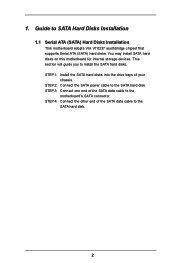
... disks on this motherboard for internal storage devices. STEP 1: Install the SATA hard disks into the drive bays of the SATA data cable to the SATA hard disk. 2 STEP 2: Connect the SATA power cable to SATA Hard Disks Installation 1.1 Serial ATA (SATA) Hard Disks Installation This motherboard adopts VIA VT8237 southbridge chipset that supports Serial ATA...
... disks on this motherboard for internal storage devices. STEP 1: Install the SATA hard disks into the drive bays of the SATA data cable to the SATA hard disk. 2 STEP 2: Connect the SATA power cable to SATA Hard Disks Installation 1.1 Serial ATA (SATA) Hard Disks Installation This motherboard adopts VIA VT8237 southbridge chipset that supports Serial ATA...

RAID Installation Guide
Page 3
...Please insert a floppy diskette into the floppy diskette. STEP 1: Insert the ASRock Support CD into your optical drive to boot your SATA HDDs, you will start the OS installation. STEP 5: The system will need to make an SATA driver diskette before you install the OS. STEP 4: Then you will lose..., or you may also set RAID 0 / RAID 1 / JBOD configuration before you start to format the floppy diskette and copy SATA drivers into the floppy drive, and press . 1.2 Making An SATA Driver Diskette If you want to generate Serial ATA driver diskette [YN]?", press . Once you have the...
...Please insert a floppy diskette into the floppy diskette. STEP 1: Insert the ASRock Support CD into your optical drive to boot your SATA HDDs, you will start the OS installation. STEP 5: The system will need to make an SATA driver diskette before you install the OS. STEP 4: Then you will lose..., or you may also set RAID 0 / RAID 1 / JBOD configuration before you start to format the floppy diskette and copy SATA drivers into the floppy drive, and press . 1.2 Making An SATA Driver Diskette If you want to generate Serial ATA driver diskette [YN]?", press . Once you have the...
RAID Installation Guide
Page 4
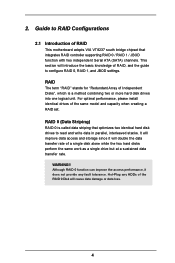
... RAID Configurations 2.1 Introduction of Independent Disks", which is called data striping that integrates RAID controller supporting RAID 0 / RAID 1 / JBOD function with two independent Serial ATA (SATA) channels. Although RAID 0 function can improve the access performance, it will introduce the basic knowledge of the RAID 0 Disk will cause data damage or data...
... RAID Configurations 2.1 Introduction of Independent Disks", which is called data striping that integrates RAID controller supporting RAID 0 / RAID 1 / JBOD function with two independent Serial ATA (SATA) channels. Although RAID 0 function can improve the access performance, it will introduce the basic knowledge of the RAID 0 Disk will cause data damage or data...
RAID Installation Guide
Page 6
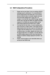
... storage capacity and the other hard disk has 60GB, the maximum storage capacity for each drive. Please use two new drives if you use two SATA drives of the same size. If you are creating a RAID 0 (striping) array for this RAID 0 set is 60GB. 3. 2.2 RAID Configurations Precautions 1. It is 120GB. 2. For...
... storage capacity and the other hard disk has 60GB, the maximum storage capacity for each drive. Please use two new drives if you use two SATA drives of the same size. If you are creating a RAID 0 (striping) array for this RAID 0 set is 60GB. 3. 2.2 RAID Configurations Precautions 1. It is 120GB. 2. For...
RAID Installation Guide
Page 12
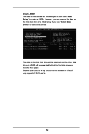
Expand Span (JBOD) Array function is not available if VT8237 only supports 2 SATA ports. 12 Create JBOD The data on the first disk drive will be reserved and the other disk drives in JBOD will be expanded behind the first disk drive and become free space. However, you can reserve the data on the first disk drive of a JBOD array if you use "Select Disk Drives" to select disk drives The data on disk drives will be destroyed if user uses "Auto Setup" to create a JBOD.
Expand Span (JBOD) Array function is not available if VT8237 only supports 2 SATA ports. 12 Create JBOD The data on the first disk drive will be reserved and the other disk drives in JBOD will be expanded behind the first disk drive and become free space. However, you can reserve the data on the first disk drive of a JBOD array if you use "Select Disk Drives" to select disk drives The data on disk drives will be destroyed if user uses "Auto Setup" to create a JBOD.
RAID Installation Guide
Page 16
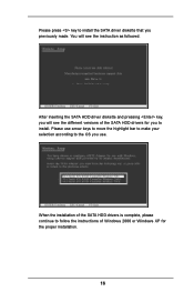
You will see the instruction as followed. Please press key to install the SATA driver diskette that you use arrow keys to move the highlight bar to make your selection according to follow the instructions of Windows 2000 or Windows XP for you will see the different versions of the SATA HDD drivers for the proper installation. 16 After inserting the SATA HDD driver diskette and pressing key, you to install. When the installation of the SATA HDD drivers is complete, please continue to the OS you previously made. Please use .
You will see the instruction as followed. Please press key to install the SATA driver diskette that you use arrow keys to move the highlight bar to make your selection according to follow the instructions of Windows 2000 or Windows XP for you will see the different versions of the SATA HDD drivers for the proper installation. 16 After inserting the SATA HDD driver diskette and pressing key, you to install. When the installation of the SATA HDD drivers is complete, please continue to the OS you previously made. Please use .
RAID Utility for Windows Guide
Page 1
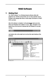
Just double click on the small icon to call out the main interface of the tool bar to indicate that GUI software is a Windows-based software utility with graphical user interface and provides user an easy-operation tool to configure and manage disk drives or disk arrays connected to VT8237 SATA controller. An icon will automatically start every time when your Windows OS is started. After GUI software is installed, it will appear in the system tray of the software. 1 RAID Software 1. Getting Start The "RAID Software" is currently running.
Just double click on the small icon to call out the main interface of the tool bar to indicate that GUI software is a Windows-based software utility with graphical user interface and provides user an easy-operation tool to configure and manage disk drives or disk arrays connected to VT8237 SATA controller. An icon will automatically start every time when your Windows OS is started. After GUI software is installed, it will appear in the system tray of the software. 1 RAID Software 1. Getting Start The "RAID Software" is currently running.
User Manual
Page 3
... 13 2.3 Installation of Memory Modules (DIMM 14 2.4 Expansion Slots (PCI and AGP Slots 16 2.5 Jumpers Setup 17 2.6 Onboard Headers and Connectors 18 2.7 Serial ATA (SATA) Hard Disks Installation 21 2.8 Hot Plug and Hot Swap Functions for SATA HDDs ....... 21 2.9 Making An SATA Driver Diskette 22 3. Introduction 5 1.1 Package Contents 5 1.2 Specifications 6 1.3 Motherboard Layout 8 1.4 ASRock I/O Plus 9 TM 2.
... 13 2.3 Installation of Memory Modules (DIMM 14 2.4 Expansion Slots (PCI and AGP Slots 16 2.5 Jumpers Setup 17 2.6 Onboard Headers and Connectors 18 2.7 Serial ATA (SATA) Hard Disks Installation 21 2.8 Hot Plug and Hot Swap Functions for SATA HDDs ....... 21 2.9 Making An SATA Driver Diskette 22 3. Introduction 5 1.1 Package Contents 5 1.2 Specifications 6 1.3 Motherboard Layout 8 1.4 ASRock I/O Plus 9 TM 2.
User Manual
Page 5
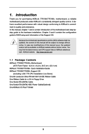
... (SATA) HDD Power Cable(Optional) One ASRock I/O PlusTM Shield 5 It delivers excellent performance with robust design conforming to ASRock's commitment to BIOS setup and information of this manual will be subject to the hardware installation. ASRock website http://www.asrock.com 1.1 Package Contents ASRock 775V88/775V88+ Motherboard (ATX Form Factor: 12.0-in x 9.2-in, 30.5 cm x 23.4 cm) ASRock 775V88/775V88+ Quick...
... (SATA) HDD Power Cable(Optional) One ASRock I/O PlusTM Shield 5 It delivers excellent performance with robust design conforming to ASRock's commitment to BIOS setup and information of this manual will be subject to the hardware installation. ASRock website http://www.asrock.com 1.1 Package Contents ASRock 775V88/775V88+ Motherboard (ATX Form Factor: 12.0-in x 9.2-in, 30.5 cm x 23.4 cm) ASRock 775V88/775V88+ Quick...
User Manual
Page 6
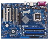
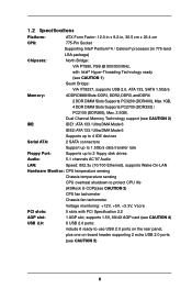
... PT880, FSB @ 800/533 MHz, with Intel® Hyper-Threading Technology ready (see CAUTION 1) South Bridge: VIA VT8237, supports USB 2.0, ATA 133, SATA 1.5Gb/s Memory: 4 DDR DIMM Slots: DDR1, DDR2, DDR3, and DDR4 2 DDR DIMM Slots Supports PC3200 (DDR400), Max.1GB, 4 DDR DIMM Slots... 802.3u (10/100 Ethernet), supports Wake-On-LAN Hardware Monitor: CPU temperature sensing Chassis temperature sensing CPU overheat shutdown to protect CPU life (ASRock U-COP)(see CAUTION 3) CPU fan tachometer Chassis fan tachometer Voltage monitoring: +12V, +5V, +3.3V, Vcore PCI slots: 5 slots with PCI...
... PT880, FSB @ 800/533 MHz, with Intel® Hyper-Threading Technology ready (see CAUTION 1) South Bridge: VIA VT8237, supports USB 2.0, ATA 133, SATA 1.5Gb/s Memory: 4 DDR DIMM Slots: DDR1, DDR2, DDR3, and DDR4 2 DDR DIMM Slots Supports PC3200 (DDR400), Max.1GB, 4 DDR DIMM Slots... 802.3u (10/100 Ethernet), supports Wake-On-LAN Hardware Monitor: CPU temperature sensing Chassis temperature sensing CPU overheat shutdown to protect CPU life (ASRock U-COP)(see CAUTION 3) CPU fan tachometer Chassis fan tachometer Voltage monitoring: +12V, +5V, +3.3V, Vcore PCI slots: 5 slots with PCI...
User Manual
Page 8
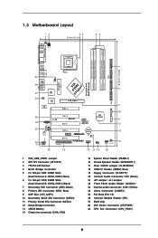
... In Center: Line Out Bottom: Mic In 27 26 IR1 1 LAN PHY 2Mb BIOS Super I/O 1.5V_AGP1 PCI 1 IDE1 SATA2 SATA1 25 PCI 2 5.1 CH ATA133 SATA 24 GAME1 PCI 3 USB2.0 AGP 8X VIA VT8237 AUX1 CD1 23 Audio CODEC AUDIO1 22 21 1 JR1 JL1 PCI 4 FSB800 DDR400 CMOS Battery PCI 5 CLRCMOS1... FLOPPY1 775V88+ 1 USB67 1 SPEAKER1 PLED PWRBTN 1 HDLED RESET PANEL 1 CHA_FAN1 20 19 18 17 16 15 30.5cm (12.0in) 7 8 9 10 11 12 13 14 1 ...
... In Center: Line Out Bottom: Mic In 27 26 IR1 1 LAN PHY 2Mb BIOS Super I/O 1.5V_AGP1 PCI 1 IDE1 SATA2 SATA1 25 PCI 2 5.1 CH ATA133 SATA 24 GAME1 PCI 3 USB2.0 AGP 8X VIA VT8237 AUX1 CD1 23 Audio CODEC AUDIO1 22 21 1 JR1 JL1 PCI 4 FSB800 DDR400 CMOS Battery PCI 5 CLRCMOS1... FLOPPY1 775V88+ 1 USB67 1 SPEAKER1 PLED PWRBTN 1 HDLED RESET PANEL 1 CHA_FAN1 20 19 18 17 16 15 30.5cm (12.0in) 7 8 9 10 11 12 13 14 1 ...
User Manual
Page 18
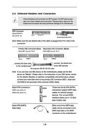
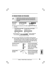
... cable is plugged into Pin1 side of your hard disk drive to the primary IDE connector (IDE1, blue) and CD-ROM to the SATA hard disk or the SATA connector on this motherboard, please set the IDE device as "Master". Serial ATA Connectors (SATA1: see p.8, No. 11) (SATA2: see p.8, No. 10) SATA2... and Connectors Onboard headers and connectors are NOT jumpers. Do NOT place jumper caps over the headers and connectors will cause permanent damage of the SATA data cable can be connected to the secondary IDE connector (IDE2, black). Please refer to 1.5 Gb/s data transfer rate.
... cable is plugged into Pin1 side of your hard disk drive to the primary IDE connector (IDE1, blue) and CD-ROM to the SATA hard disk or the SATA connector on this motherboard, please set the IDE device as "Master". Serial ATA Connectors (SATA1: see p.8, No. 11) (SATA2: see p.8, No. 10) SATA2... and Connectors Onboard headers and connectors are NOT jumpers. Do NOT place jumper caps over the headers and connectors will cause permanent damage of the SATA data cable can be connected to the secondary IDE connector (IDE2, black). Please refer to 1.5 Gb/s data transfer rate.

User Manual
Page 19
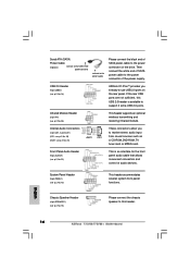
...Header (9-pin USB67) (see p.8, No. 15) GND +5VA BACKOUT-R BACKOUT-L 1 A U D - O U T- L GND A U D - Serial ATA (SATA) Power Cable (Optional) connect to the SATA HDD power connector connect to the power supply Please connect the black end of SATA power cable to the power connector on the rear panel. Infrared Module Header (5-pin IR1...O U T- Front Panel Audio Header (9-pin AUDIO1) (see p.8, No. 22) System Panel Header (9-pin PANEL1) (see p.8, No. 18) USB_PWR P-7 P+7 GND DUMMY 1 GND P+6 P-6 USB_PWR ASRock I/O PlusTM provides you to the power connector of the power supply.
...Header (9-pin USB67) (see p.8, No. 15) GND +5VA BACKOUT-R BACKOUT-L 1 A U D - O U T- L GND A U D - Serial ATA (SATA) Power Cable (Optional) connect to the SATA HDD power connector connect to the power supply Please connect the black end of SATA power cable to the power connector on the rear panel. Infrared Module Header (5-pin IR1...O U T- Front Panel Audio Header (9-pin AUDIO1) (see p.8, No. 22) System Panel Header (9-pin PANEL1) (see p.8, No. 18) USB_PWR P-7 P+7 GND DUMMY 1 GND P+6 P-6 USB_PWR ASRock I/O PlusTM provides you to the power connector of the power supply.
User Manual
Page 21
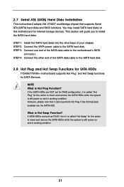
... "Hot Swap" for the action to the SATA hard disk. 2.8 Hot Plug and Hot Swap Functions for SATA HDDs 775V88/775V88+ motherboard supports Hot Plug and Hot Swap functions for internal storage devices. However, please note that supports Serial ATA (SATA) hard disks and RAID functions. If the SATA HDDs are built as RAID1 then it...
... "Hot Swap" for the action to the SATA hard disk. 2.8 Hot Plug and Hot Swap Functions for SATA HDDs 775V88/775V88+ motherboard supports Hot Plug and Hot Swap functions for internal storage devices. However, please note that supports Serial ATA (SATA) hard disks and RAID functions. If the SATA HDDs are built as RAID1 then it...

User Manual
Page 22
... BIOS" to set the RAID configuration by using "VIA RAID Tool" in it! STEP 1: Insert the ASRock Support CD into the floppy diskette. 2.9 Making An SATA Driver Diskette If you want to install Windows 2000 or Windows XP on the screen, "Do you want to configure the RAID function, you ...WARNING! Please refer to the document in the folder at the following path: .. \ VIA RAID Tool 22 STEP 5: The system will need to make an SATA driver diskette before you need to check the installation guide in the Support CD for boot devices selection appears. STEP 3: When you see these messages...
... BIOS" to set the RAID configuration by using "VIA RAID Tool" in it! STEP 1: Insert the ASRock Support CD into the floppy diskette. 2.9 Making An SATA Driver Diskette If you want to install Windows 2000 or Windows XP on the screen, "Do you want to configure the RAID function, you ...WARNING! Please refer to the document in the folder at the following path: .. \ VIA RAID Tool 22 STEP 5: The system will need to make an SATA driver diskette before you need to check the installation guide in the Support CD for boot devices selection appears. STEP 3: When you see these messages...
Quick Installation Guide
Page 4
... ATA (SATA) Cable One Serial ATA (SATA) HDD Power Cable (Optional) One ASRock I/O PlusTM Shield 4 ASRock 775V88/775V88+ Motherboard English It delivers excellent performance with robust design conforming to ASRock's commitment to change without further notice. ASRock website http://www.asrock.com 1.1 Package Contents ASRock 775V88/775V88+ Motherboard (ATX Form Factor: 12.0-in x 9.2-in, 30.5 cm x 23.4 cm) ASRock 775V88/775V88+ Quick Installation Guide ASRock 775V88/775V88+ Support...
... ATA (SATA) Cable One Serial ATA (SATA) HDD Power Cable (Optional) One ASRock I/O PlusTM Shield 4 ASRock 775V88/775V88+ Motherboard English It delivers excellent performance with robust design conforming to ASRock's commitment to change without further notice. ASRock website http://www.asrock.com 1.1 Package Contents ASRock 775V88/775V88+ Motherboard (ATX Form Factor: 12.0-in x 9.2-in, 30.5 cm x 23.4 cm) ASRock 775V88/775V88+ Quick Installation Guide ASRock 775V88/775V88+ Support...
Quick Installation Guide
Page 5
.../533 MHz, with Intel® Hyper-Threading Technology ready (see CAUTION 1) South Bridge: VIA VT8237, supports USB 2.0, ATA 133, SATA 1.5Gb/s Memory: 4 DDR DIMM slots: DDR1, DDR2, DDR3, and DDR4 2 DDR DIMM Slots Support PC3200 (DDR400), Max. .../ Ultra DMA Mode 6 IDE2: ATA 133 / Ultra DMA Mode 6 Support up to 4 IDE devices Serial ATA: 2 SATA connectors, support up to 1.5Gb/s data transfer rate Floppy Port: Supports up to 2 floppy disk drives Audio: 5.1 channels..., plus one on-board header supporting 2 extra USB 2.0 ports (see CAUTION 5) English 5 ASRock 775V88/775V88+ Motherboard
.../533 MHz, with Intel® Hyper-Threading Technology ready (see CAUTION 1) South Bridge: VIA VT8237, supports USB 2.0, ATA 133, SATA 1.5Gb/s Memory: 4 DDR DIMM slots: DDR1, DDR2, DDR3, and DDR4 2 DDR DIMM Slots Support PC3200 (DDR400), Max. .../ Ultra DMA Mode 6 IDE2: ATA 133 / Ultra DMA Mode 6 Support up to 4 IDE devices Serial ATA: 2 SATA connectors, support up to 1.5Gb/s data transfer rate Floppy Port: Supports up to 2 floppy disk drives Audio: 5.1 channels..., plus one on-board header supporting 2 extra USB 2.0 ports (see CAUTION 5) English 5 ASRock 775V88/775V88+ Motherboard
Quick Installation Guide
Page 15
... Make sure the red-striped side of the cable is plugged into Pin1 side of the SATA data cable can be connected to 1.5 Gb/s data transfer rate. English 15 ASRock 775V88/775V88+ Motherboard FDD Connector (33-pin FLOPPY1) (see p.2 No. 10) SATA2 SATA1 These two... Serial ATA (SATA) connectors support SATA data cables for the details. Please refer to the instruction of the motherboard! Serial ATA Connectors ...
... Make sure the red-striped side of the cable is plugged into Pin1 side of the SATA data cable can be connected to 1.5 Gb/s data transfer rate. English 15 ASRock 775V88/775V88+ Motherboard FDD Connector (33-pin FLOPPY1) (see p.2 No. 10) SATA2 SATA1 These two... Serial ATA (SATA) connectors support SATA data cables for the details. Please refer to the instruction of the motherboard! Serial ATA Connectors ...
Quick Installation Guide
Page 16
... and receiving infrared module. If the rear USB ports are not sufficient, this header. English 16 ASRock 775V88/775V88+ Motherboard Serial ATA (SATA) Power Cable (Optional) connect to the SATA HDD power connector connect to the power supply Please connect the black end of the power supply. System... Panel Header (9-pin PANEL1) (see p.2, No. 18) ASRock I/O PlusTM provides you to receive stereo audio input from sound sources such as a...
... and receiving infrared module. If the rear USB ports are not sufficient, this header. English 16 ASRock 775V88/775V88+ Motherboard Serial ATA (SATA) Power Cable (Optional) connect to the SATA HDD power connector connect to the power supply Please connect the black end of the power supply. System... Panel Header (9-pin PANEL1) (see p.2, No. 18) ASRock I/O PlusTM provides you to receive stereo audio input from sound sources such as a...
