User Manual
Page 5
... a 3.5-in Floppy Drive One Serial ATA (SATA) Cable One Serial ATA (SATA) HDD Power Cable(Optional) One ASRock I/O PlusTM Shield 5 In this manual, chapter 1 and 2 contain introduction of this manual will be available on ASRock website as well. In case any modifications of the motherboard and step-bystep guide to the hardware installation. You may find the latest memory and CPU support lists on ASRock website without notice. Chapter 3 and 4 contain the configuration guide to BIOS setup and...
... a 3.5-in Floppy Drive One Serial ATA (SATA) Cable One Serial ATA (SATA) HDD Power Cable(Optional) One ASRock I/O PlusTM Shield 5 In this manual, chapter 1 and 2 contain introduction of this manual will be available on ASRock website as well. In case any modifications of the motherboard and step-bystep guide to the hardware installation. You may find the latest memory and CPU support lists on ASRock website without notice. Chapter 3 and 4 contain the configuration guide to BIOS setup and...
User Manual
Page 7
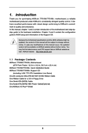
... BIOS Supports "Plug and Play" ACPI 1.1 compliance wake up events Supports jumperfree SMBIOS 2.3.1 support CPU frequency stepless control (only for proper installation. 3. Power Management for USB 2.0 works fine under Microsoft® Windows® 98 / ME. 6. While CPU overheat is not recommended to perform over-clocking. Although this motherboard! About the setting of the system or damage the CPU. 7 ASRock I/O PlusTM: 1 PS/2 mouse port, 1 PS/2 keyboard port, 1 serial port: COM1, 1 parallel port: ECP/EPP support, 6 ready-to-use a 3.3V AGP card...
... BIOS Supports "Plug and Play" ACPI 1.1 compliance wake up events Supports jumperfree SMBIOS 2.3.1 support CPU frequency stepless control (only for proper installation. 3. Power Management for USB 2.0 works fine under Microsoft® Windows® 98 / ME. 6. While CPU overheat is not recommended to perform over-clocking. Although this motherboard! About the setting of the system or damage the CPU. 7 ASRock I/O PlusTM: 1 PS/2 mouse port, 1 PS/2 keyboard port, 1 serial port: COM1, 1 parallel port: ECP/EPP support, 6 ready-to-use a 3.3V AGP card...
User Manual
Page 13
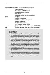
Step 2. Place the heatsink onto the socket. Repeat with the motherboard throughholes. Step 6. Then connect the CPU fan to the instruction manuals of your CPU fan and heatsink. Align fasteners with remaining fasteners. Before you installed the heatsink, you press down on fastener caps with thumb to dissipate heat. Step 3. Connect fan header with Intel 775-LAND CPU to install and lock. Ensure that supports Intel 775-LAND CPU. Step 1. If...
Step 2. Place the heatsink onto the socket. Repeat with the motherboard throughholes. Step 6. Then connect the CPU fan to the instruction manuals of your CPU fan and heatsink. Align fasteners with remaining fasteners. Before you installed the heatsink, you press down on fastener caps with thumb to dissipate heat. Step 3. Connect fan header with Intel 775-LAND CPU to install and lock. Ensure that supports Intel 775-LAND CPU. Step 1. If...
User Manual
Page 26
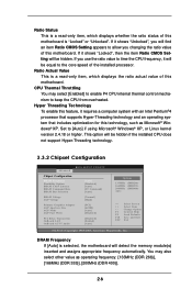
... select [Enabled] to enable P4 CPU internal thermal control mechanism to [Auto] if using Microsoft® Windows® XP, or Linux kernel version 2.4.18 or higher. If you changing the ratio value of this motherboard. Hyper Threading Technology To enable this feature, it will be hidden if the installed CPU does not support Hyper-Threading technology. 3.3.2 Chipset Configuration BIOS SETUP UTILITY Advanced Chipset Configuration DRAM Frequency Flexibility Option DRAM CAS# Latency DRAM Command Rate DRAM Bus Selection [Auto] [Disabled] [Auto] [2T Command] [Auto] DRAM Voltage AGP Voltage...
... select [Enabled] to enable P4 CPU internal thermal control mechanism to [Auto] if using Microsoft® Windows® XP, or Linux kernel version 2.4.18 or higher. If you changing the ratio value of this motherboard. Hyper Threading Technology To enable this feature, it will be hidden if the installed CPU does not support Hyper-Threading technology. 3.3.2 Chipset Configuration BIOS SETUP UTILITY Advanced Chipset Configuration DRAM Frequency Flexibility Option DRAM CAS# Latency DRAM Command Rate DRAM Bus Selection [Auto] [Disabled] [Auto] [2T Command] [Auto] DRAM Voltage AGP Voltage...

User Manual
Page 29
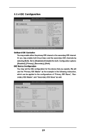
... Mode DMA Mode S.M.A.R.T. 32Bit Data Transfer :Hard Disk :ST340014A :40.0 GB :Supported :16Sectors :4 :MultiWord DMA-2 :Ultra DMA-5 :Supported [Auto] [Auto] [Auto] [Auto] [Auto] [Disabled] [Disabled] Select the type of "Primary IDE Slave", "Secondary IDE Master", and "Secondary IDE Slave" as the example in the following instruction, which can be applied to the configurations of device connected to [Disabled] will use the "Primary IDE Master" as well. OnBoard IDE Controller You may enable either the primary IDE channel or the secondary IDE channel...
... Mode DMA Mode S.M.A.R.T. 32Bit Data Transfer :Hard Disk :ST340014A :40.0 GB :Supported :16Sectors :4 :MultiWord DMA-2 :Ultra DMA-5 :Supported [Auto] [Auto] [Auto] [Auto] [Auto] [Disabled] [Disabled] Select the type of "Primary IDE Slave", "Secondary IDE Master", and "Secondary IDE Slave" as the example in the following instruction, which can be applied to the configurations of device connected to [Disabled] will use the "Primary IDE Master" as well. OnBoard IDE Controller You may enable either the primary IDE channel or the secondary IDE channel...
User Manual
Page 30
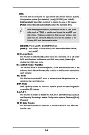
... Configuration options: [Disabled], [Auto], [Enabled]. 32-Bit Data Transfer Use this item to enable 32-bit access to enable or disable the S.M.A.R.T. (Self-Monitoring, Analysis, and Reporting Technology) feature. If this feature is [Auto]. After selecting the hard disk information into BIOS, use of IDE device. [Auto]: Select [Auto] to automatically detect the hard disk drive. Make sure to set the PIO mode to enhance hard disk performance by reading or writing more data during each transfer. for IDE ARMD (ATAPI Removable...
... Configuration options: [Disabled], [Auto], [Enabled]. 32-Bit Data Transfer Use this item to enable 32-bit access to enable or disable the S.M.A.R.T. (Self-Monitoring, Analysis, and Reporting Technology) feature. If this feature is [Auto]. After selecting the hard disk information into BIOS, use of IDE device. [Auto]: Select [Auto] to automatically detect the hard disk drive. Make sure to set the PIO mode to enhance hard disk performance by reading or writing more data during each transfer. for IDE ARMD (ATAPI Removable...

User Manual
Page 32
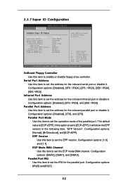
... Configure Super IO Chipset OnBoard Floppy Controller Serial Port Address Infrared Port Address Parallel Port Address Parallel Port Mode EPP Version ECP Mode DMA Channel Parallel Port IRQ OnBoard Game Port OnBoard MIDI Port [Enabled] [3F8 / IRQ4] [Disabled] [378] [ECP + EPP] [1.9] [DMA3] [IRQ7] [Enabled] [Disabled] Allow BIOS to enable or disable floppy drive controller. OnBoard Floppy Controller Use this item to [ECP+EPP], it . Parallel Port Mode Use this item to Enable or Disable Floppy Controller. +F1 F9 F10 ESC Select Screen Select Item Change Option General Help Load Defaults...
... Configure Super IO Chipset OnBoard Floppy Controller Serial Port Address Infrared Port Address Parallel Port Address Parallel Port Mode EPP Version ECP Mode DMA Channel Parallel Port IRQ OnBoard Game Port OnBoard MIDI Port [Enabled] [3F8 / IRQ4] [Disabled] [378] [ECP + EPP] [1.9] [DMA3] [IRQ7] [Enabled] [Disabled] Allow BIOS to enable or disable floppy drive controller. OnBoard Floppy Controller Use this item to [ECP+EPP], it . Parallel Port Mode Use this item to Enable or Disable Floppy Controller. +F1 F9 F10 ESC Select Screen Select Item Change Option General Help Load Defaults...
User Manual
Page 33
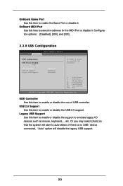
... SETUP UTILITY USB Configuration USB Devices Enabled : None USB Controller USB 2.0 Support Legacy USB Support [Enabled] [Enabled] [Disabled] To enable or disable the onboard USB controllers. +F1 F9 F10 ESC Select Screen Select Item Change Option General Help Load Defaults Save and Exit Exit v02.54 (C) Copyright 1985-2003, American Megatrends, Inc. USB 2.0 Support Use this item to emulate legacy I/O devices such as mouse, keyboard,... Or you may select [Auto] so that the system will disable the legacy USB support. 33 etc. if there is no USB device connected, "Auto" option will start...
... SETUP UTILITY USB Configuration USB Devices Enabled : None USB Controller USB 2.0 Support Legacy USB Support [Enabled] [Enabled] [Disabled] To enable or disable the onboard USB controllers. +F1 F9 F10 ESC Select Screen Select Item Change Option General Help Load Defaults Save and Exit Exit v02.54 (C) Copyright 1985-2003, American Megatrends, Inc. USB 2.0 Support Use this item to emulate legacy I/O devices such as mouse, keyboard,... Or you may select [Auto] so that the system will disable the legacy USB support. 33 etc. if there is no USB device connected, "Auto" option will start...
User Manual
Page 35
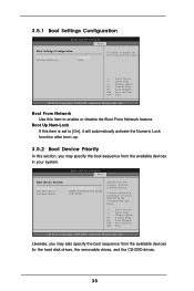
... hard disk drives, the removable drives, and the CD/DVD drives. 35 BIOS SETUP UTILITY Boot Boot Device Priority 1st Boot Device 2nd Boot Device 3rd Boot Device [1st FLOPPY DRIVE] [HDD: PM-MAXTOR 6L08] [CD / DVD] Specifies the boot sequence from network feature. +F1 F9 F10 ESC Select Screen Select Item Change Option General Help Load Defaults Save and Exit Exit v02.54 (C) Copyright 1985-2003, American Megatrends, Inc. 3.5.1 Boot Settings Configuration BIOS SETUP UTILITY Boot Boot Settings Configuration Boot From Network Bootup Num-Lock [Disabled] [On] To enable or disable the boot...
... hard disk drives, the removable drives, and the CD/DVD drives. 35 BIOS SETUP UTILITY Boot Boot Device Priority 1st Boot Device 2nd Boot Device 3rd Boot Device [1st FLOPPY DRIVE] [HDD: PM-MAXTOR 6L08] [CD / DVD] Specifies the boot sequence from network feature. +F1 F9 F10 ESC Select Screen Select Item Change Option General Help Load Defaults Save and Exit Exit v02.54 (C) Copyright 1985-2003, American Megatrends, Inc. 3.5.1 Boot Settings Configuration BIOS SETUP UTILITY Boot Boot Settings Configuration Boot From Network Bootup Num-Lock [Disabled] [On] To enable or disable the boot...
User Manual
Page 38
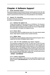
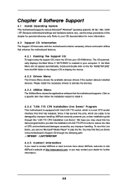
... equipped with the motherboard contains necessary drivers and useful utilities that came with Intel LGA 775 socket, which is enabled in your CD-ROM drive. We hope you may find this Live Demo in this Live Demo, you need to contact ASRock or want to play the file. Because motherboard settings and hardware options vary, use the setup procedures in the motherboard's Support CD through this live...
... equipped with the motherboard contains necessary drivers and useful utilities that came with Intel LGA 775 socket, which is enabled in your CD-ROM drive. We hope you may find this Live Demo in this Live Demo, you need to contact ASRock or want to play the file. Because motherboard settings and hardware options vary, use the setup procedures in the motherboard's Support CD through this live...
Quick Installation Guide
Page 2
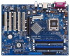
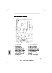
... 17 Clear CMOS Jumper (CLRCMOS1) 18 USB 2.0 Header (USB67, Blue) 19 Floppy Connector (FLOPPY1) 20 Internal Audio Connector: CD1 (Black) 21 JR1 / JL1 Jumper 22 Front Panel Audio Header (AUDIO1) 23 Internal audio connector: AUX1 (White) 24 Game Connector (GAME1) 25 PCI Slots (PCI 1-5) 26 Infrared Module Header (IR1) 27 BIOS chip 28 ATX Power Connector (ATXPWR1) 29 CPU Fan Connector (CPU_FAN1) 2 ASRock 775V88/775V88+ Motherboard Motherboard Layout English 1 PS2_USB_PWR1 Jumper 2 ATX Power Connector (ATX12V1) 3 775-Pin CPU Socket 4 North Bridge Controller 5 2 x 184-pin DDR DIMM Slots (Dual...
... 17 Clear CMOS Jumper (CLRCMOS1) 18 USB 2.0 Header (USB67, Blue) 19 Floppy Connector (FLOPPY1) 20 Internal Audio Connector: CD1 (Black) 21 JR1 / JL1 Jumper 22 Front Panel Audio Header (AUDIO1) 23 Internal audio connector: AUX1 (White) 24 Game Connector (GAME1) 25 PCI Slots (PCI 1-5) 26 Infrared Module Header (IR1) 27 BIOS chip 28 ATX Power Connector (ATXPWR1) 29 CPU Fan Connector (CPU_FAN1) 2 ASRock 775V88/775V88+ Motherboard Motherboard Layout English 1 PS2_USB_PWR1 Jumper 2 ATX Power Connector (ATX12V1) 3 775-Pin CPU Socket 4 North Bridge Controller 5 2 x 184-pin DDR DIMM Slots (Dual...
Quick Installation Guide
Page 10
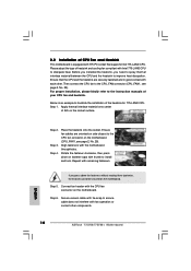
... the socket surface. Then connect the CPU fan to the CPU_FAN connector (CPU_FAN1, see page 2, No. 29). For proper installation, please kindly refer to the instruction manuals of your CPU fan and heatsink. Step 3. Repeat with fan operation or contact other . Before you installed the heatsink, you press down on the motherboard. Connect fan header with the CPU fan connector on fastener caps with each other components. 10 ASRock 775V88/775V88+ Motherboard English Secure excess cable...
... the socket surface. Then connect the CPU fan to the CPU_FAN connector (CPU_FAN1, see page 2, No. 29). For proper installation, please kindly refer to the instruction manuals of your CPU fan and heatsink. Step 3. Repeat with fan operation or contact other . Before you installed the heatsink, you press down on the motherboard. Connect fan header with the CPU fan connector on fastener caps with each other components. 10 ASRock 775V88/775V88+ Motherboard English Secure excess cable...
Quick Installation Guide
Page 19
... the Support CD, "Guide to SATA Hard Disks Installation and RAID Configuration", which is located in the folder at the beginning of system boot-up, press key, and then a window for boot devices selection appears. Insert the ASRock Support CD into the floppy drive, and press . B. Formatting the floppy diskette will lose ALL data in the Support CD for proper configuration. E. STEP 2: Use "SATA RAID BIOS" to set RAID configuration, you can start to install Windows 2000 / Windows XP on the screen, "Do...
... the Support CD, "Guide to SATA Hard Disks Installation and RAID Configuration", which is located in the folder at the beginning of system boot-up, press key, and then a window for boot devices selection appears. Insert the ASRock Support CD into the floppy drive, and press . B. Formatting the floppy diskette will lose ALL data in the Support CD for proper configuration. E. STEP 2: Use "SATA RAID BIOS" to set RAID configuration, you can start to install Windows 2000 / Windows XP on the screen, "Do...

Quick Installation Guide
Page 20
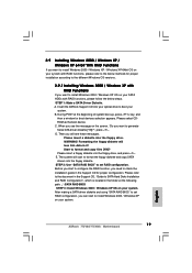
B. The SATA 64-bit drivers are allowed to use "VIA RAID Tool" in Windows environment, please install SATA drivers from the Support CD again so that "VIA RAID Tool" will be installed to your system. Insert the floppy diskette into your floppy diskette. Copy the SATA 64-bit drivers to your floppy drive. A. After making a SATA driver diskette, you can start to install Windows XP 64bit on your system as well. 20 ASRock 775V88/775V88+ Motherboard English Windows 98 / Windows ME...
B. The SATA 64-bit drivers are allowed to use "VIA RAID Tool" in Windows environment, please install SATA drivers from the Support CD again so that "VIA RAID Tool" will be installed to your system. Insert the floppy diskette into your floppy diskette. Copy the SATA 64-bit drivers to your floppy drive. A. After making a SATA driver diskette, you can start to install Windows XP 64bit on your system as well. 20 ASRock 775V88/775V88+ Motherboard English Windows 98 / Windows ME...
Quick Installation Guide
Page 22
... the motherboard contains necessary drivers and useful utilities that came with its various sub-menus and to scroll through its test routines. It is designed to display the menus. 22 ASRock 775V88/775V88+ Motherboard English If the Main Menu does not appear automatically, locate and double-click on the motherboard stores BIOS Setup Utility. 3. For the detailed information about BIOS Setup, please refer to the User Manual (PDF file) contained in the Support...
... the motherboard contains necessary drivers and useful utilities that came with its various sub-menus and to scroll through its test routines. It is designed to display the menus. 22 ASRock 775V88/775V88+ Motherboard English If the Main Menu does not appear automatically, locate and double-click on the motherboard stores BIOS Setup Utility. 3. For the detailed information about BIOS Setup, please refer to the User Manual (PDF file) contained in the Support...
User Manual
Page 29
...-5 :Supported [Auto] [Auto] [Auto] [Auto] [Auto] [Disabled] [Disabled] Select the type of device connected to the configurations of "Primary IDE Slave", "Secondary IDE Master", and "Secondary IDE Slave" as the example in the following instruction, which can be applied to the system. +F1 F9 F10 ESC Select Screen Select Item Change Option General Help Load Defaults Save and Exit Exit v02.54 (C) Copyright 1985-2003, American Megatrends, Inc. 29 3.3.4 IDE Configuration Advanced BIOS SETUP UTILITY IDE Configuration OnBoard IDE Controller Primary IDE...
...-5 :Supported [Auto] [Auto] [Auto] [Auto] [Auto] [Disabled] [Disabled] Select the type of device connected to the configurations of "Primary IDE Slave", "Secondary IDE Master", and "Secondary IDE Slave" as the example in the following instruction, which can be applied to the system. +F1 F9 F10 ESC Select Screen Select Item Change Option General Help Load Defaults Save and Exit Exit v02.54 (C) Copyright 1985-2003, American Megatrends, Inc. 29 3.3.4 IDE Configuration Advanced BIOS SETUP UTILITY IDE Configuration OnBoard IDE Controller Primary IDE...

User Manual
Page 30
Configuration options: [Not Installed], [Auto], [CD/DVD], and [ARMD]. [Not Installed]: Select [Not Installed] to disable the use a disk utility, such as MO. LBA/Large Mode Use this item to enable or disable the S.M.A.R.T. (Self-Monitoring, Analysis, and Reporting Technology) feature. Block (Multi-Sector Transfer) The default value of IDE device. [Auto]: Select [Auto] to automatically detect the hard disk drive. If this feature is used for compatible IDE devices. S.M.A.R.T. Use this item to select the LBA/Large mode for Netware and...
Configuration options: [Not Installed], [Auto], [CD/DVD], and [ARMD]. [Not Installed]: Select [Not Installed] to disable the use a disk utility, such as MO. LBA/Large Mode Use this item to enable or disable the S.M.A.R.T. (Self-Monitoring, Analysis, and Reporting Technology) feature. Block (Multi-Sector Transfer) The default value of IDE device. [Auto]: Select [Auto] to automatically detect the hard disk drive. If this feature is used for compatible IDE devices. S.M.A.R.T. Use this item to select the LBA/Large mode for Netware and...
User Manual
Page 32
...Configuration options: [Disabled], [378], and [278]. 3.3.7 Super IO Configuration Advanced BIOS SETUP UTILITY Configure Super IO Chipset OnBoard Floppy Controller Serial Port Address Infrared Port Address Parallel Port Address Parallel Port Mode EPP Version ECP Mode DMA Channel Parallel Port IRQ OnBoard Game Port OnBoard MIDI Port [Enabled] [3F8 / IRQ4] [Disabled] [378] [ECP + EPP] [1.9] [DMA3] [IRQ7] [Enabled] [Disabled] Allow BIOS to set the address for the onboard parallel port or disable it. EPP Version Use this item to set the ECP mode DMA channel. ECP Mode DMA Channel Use...
...Configuration options: [Disabled], [378], and [278]. 3.3.7 Super IO Configuration Advanced BIOS SETUP UTILITY Configure Super IO Chipset OnBoard Floppy Controller Serial Port Address Infrared Port Address Parallel Port Address Parallel Port Mode EPP Version ECP Mode DMA Channel Parallel Port IRQ OnBoard Game Port OnBoard MIDI Port [Enabled] [3F8 / IRQ4] [Disabled] [378] [ECP + EPP] [1.9] [DMA3] [IRQ7] [Enabled] [Disabled] Allow BIOS to set the address for the onboard parallel port or disable it. EPP Version Use this item to set the ECP mode DMA channel. ECP Mode DMA Channel Use...

User Manual
Page 33
...Advanced BIOS SETUP UTILITY USB Configuration USB Devices Enabled : None USB Controller USB 2.0 Support Legacy USB Support [Enabled] [Enabled] [Disabled] To enable or disable the onboard USB controllers. +F1 F9 F10 ESC Select Screen Select Item Change Option General Help Load Defaults Save and Exit Exit v02.54 (C) Copyright 1985-2003, American Megatrends, Inc. USB Controller Use this item to enable or disable the support to auto-detect; Legacy USB Support Use this item to enable or disable the USB 2.0 support. if there is no USB device connected, "Auto" option will start...
...Advanced BIOS SETUP UTILITY USB Configuration USB Devices Enabled : None USB Controller USB 2.0 Support Legacy USB Support [Enabled] [Enabled] [Disabled] To enable or disable the onboard USB controllers. +F1 F9 F10 ESC Select Screen Select Item Change Option General Help Load Defaults Save and Exit Exit v02.54 (C) Copyright 1985-2003, American Megatrends, Inc. USB Controller Use this item to enable or disable the support to auto-detect; Legacy USB Support Use this item to enable or disable the USB 2.0 support. if there is no USB device connected, "Auto" option will start...
User Manual
Page 38
... motherboard damages caused by improper handling, ASRock sincerely presents you a clear installation guide through this Live Demo, you start the installation of LGA 775 CPU in this chapter for more information. 4.2 Support CD Information The Support CD that came with Intel LGA 775 socket, which is equipped with the motherboard contains necessary drivers and useful utilities that Intel has released. Because motherboard settings and hardware options vary, use the setup...
... motherboard damages caused by improper handling, ASRock sincerely presents you a clear installation guide through this Live Demo, you start the installation of LGA 775 CPU in this chapter for more information. 4.2 Support CD Information The Support CD that came with Intel LGA 775 socket, which is equipped with the motherboard contains necessary drivers and useful utilities that Intel has released. Because motherboard settings and hardware options vary, use the setup...


