Service Manual
Page 13
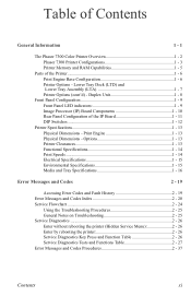
... and Codes Procedures 2 - 37 Contents xi Table of Contents General Information 1 - 1 The Phaser 7300 Color Printer Overview 1 - 2 Phaser 7300 Printer Configurations 1 - 3 Printer Memory and RAM Capabilities 1 - 5 Parts of the IP Board 1 - 11 DIP Switches 1 - 12 Printer Specifications 1 - 13 Physical Dimensions - Print Engine 1 - 13 Physical Dimensions - Duplex Unit 1 - 8 Front Panel Configuration 1 - 9 Front Panel LED indicators 1 - 9 Image Processor (IP) Board...
... and Codes Procedures 2 - 37 Contents xi Table of Contents General Information 1 - 1 The Phaser 7300 Color Printer Overview 1 - 2 Phaser 7300 Printer Configurations 1 - 3 Printer Memory and RAM Capabilities 1 - 5 Parts of the IP Board 1 - 11 DIP Switches 1 - 12 Printer Specifications 1 - 13 Physical Dimensions - Print Engine 1 - 13 Physical Dimensions - Duplex Unit 1 - 8 Front Panel Configuration 1 - 9 Front Panel LED indicators 1 - 9 Image Processor (IP) Board...
Service Manual
Page 15
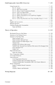
... List 7 - 193 Using the parts list 7 - 193 PL 1.0 - MPT Pick Assembly 7 - 196 PL 3.0 - Printer Unit Chassis (2 of the Imaging Units .8 - 232 Fuser and Paper Exit 8 - 233 Duplex Unit 8 - 234 Paper Jam Detection 8 - 235 Paper Size Sensing 8 - 236 ...Fuser Temperature Settings 8 - 237 Cover Open Detection 8 - 238 Toner Detection 8 - 239 Color Registration Detection 8 - 241 Customer Replaceable Consumable Detection 8 - 242 Customer Replaceable Consumable (CRC) Life Counter Behavior ..........8 - 242 Printer...
... List 7 - 193 Using the parts list 7 - 193 PL 1.0 - MPT Pick Assembly 7 - 196 PL 3.0 - Printer Unit Chassis (2 of the Imaging Units .8 - 232 Fuser and Paper Exit 8 - 233 Duplex Unit 8 - 234 Paper Jam Detection 8 - 235 Paper Size Sensing 8 - 236 ...Fuser Temperature Settings 8 - 237 Cover Open Detection 8 - 238 Toner Detection 8 - 239 Color Registration Detection 8 - 241 Customer Replaceable Consumable Detection 8 - 242 Customer Replaceable Consumable (CRC) Life Counter Behavior ..........8 - 242 Printer...
Service Manual
Page 17
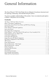
... The Xerox Phaser® 7300 Color Printer Service Manual is the primary document used for repairing, maintaining, and troubleshooting the printer. To ensure a complete understanding of the Printer ...1 - 6 Print Engine Base Configuration 1 - 6 Printer Options - Options 1 - 13 Printer Clearances ...1 - 13 Functional Specifications...1 - 14 Print Speeds ...1 - 14 Electrical Specifications ...1 - 15 Environmental Specifications 1 - 15 Media and Tray Specifications 1 - 16 General Information 1 - 1 Duplex...
... The Xerox Phaser® 7300 Color Printer Service Manual is the primary document used for repairing, maintaining, and troubleshooting the printer. To ensure a complete understanding of the Printer ...1 - 6 Print Engine Base Configuration 1 - 6 Printer Options - Options 1 - 13 Printer Clearances ...1 - 13 Functional Specifications...1 - 14 Print Speeds ...1 - 14 Electrical Specifications ...1 - 15 Environmental Specifications 1 - 15 Media and Tray Specifications 1 - 16 General Information 1 - 1 Duplex...
Service Manual
Page 54
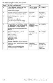
... Go to step [9]. and/or the problem motor/clutch. 2-38 Phaser 7300 Color Printer Service Manual Troubleshooting Procedure Table (cont'd.) Steps Actions and Questions Yes No... 6 Check the sensor for each motor Replace the Replace the and clutch. sensor. Replace the following motors/clutches. Exit Gate Solenoid (Duplex... Replace the Replace the sensor is in place properly. Assembly. Is there debris present? 7 Verify the wiring harness for gaps...
... Go to step [9]. and/or the problem motor/clutch. 2-38 Phaser 7300 Color Printer Service Manual Troubleshooting Procedure Table (cont'd.) Steps Actions and Questions Yes No... 6 Check the sensor for each motor Replace the Replace the and clutch. sensor. Replace the following motors/clutches. Exit Gate Solenoid (Duplex... Replace the Replace the sensor is in place properly. Assembly. Is there debris present? 7 Verify the wiring harness for gaps...
Service Manual
Page 55
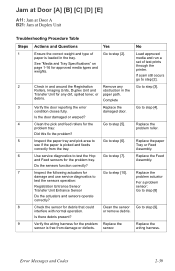
...Verify the door reporting the error condition closes fully. Assembly. interfere with normal operation. Replace the problem tray: problem roller. wiring harness. Jam at Door [A] [B] [C] [D] [E] A11: Jam at Door A B21: Jam at Duplex Unit Troubleshooting Procedure Table Steps Actions and Questions Yes ...No 1 Ensure the correct weight and type of test prints through the printer. Replace the damaged door. debris. Load approved paper is loaded in the...
...Verify the door reporting the error condition closes fully. Assembly. interfere with normal operation. Replace the problem tray: problem roller. wiring harness. Jam at Door [A] [B] [C] [D] [E] A11: Jam at Door A B21: Jam at Duplex Unit Troubleshooting Procedure Table Steps Actions and Questions Yes ...No 1 Ensure the correct weight and type of test prints through the printer. Replace the damaged door. debris. Load approved paper is loaded in the...
Service Manual
Page 56
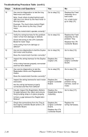
... 11 Verify the wiring harness for the problem Go to step [14]. defects? 12 Use service diagnostics to test the Duplex Go to step [12]. Duplex Unit. Is the wiring harness properly connected and free from damage or defects. Go to the LTA Controller problem Tray. Does...behind Right Door A are driven by the tray 2 feed motor. Unit motor and clutches. Replace the LTA Controller Board. 2-40 Phaser 7300 Color Printer Service Manual Assembly for gaps between the Registration Rollers? 17 Check the connections from the Tray to step [12]. Replace the LTA Is the wiring ...
... 11 Verify the wiring harness for the problem Go to step [14]. defects? 12 Use service diagnostics to test the Duplex Go to step [12]. Duplex Unit. Is the wiring harness properly connected and free from damage or defects. Go to the LTA Controller problem Tray. Does...behind Right Door A are driven by the tray 2 feed motor. Unit motor and clutches. Replace the LTA Controller Board. 2-40 Phaser 7300 Color Printer Service Manual Assembly for gaps between the Registration Rollers? 17 Check the connections from the Tray to step [12]. Replace the LTA Is the wiring ...
Service Manual
Page 80
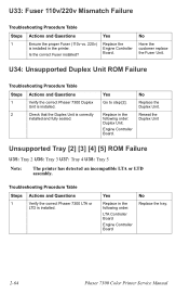
... Board Engine Controller Board No Replace the tray. 2-64 Phaser 7300 Color Printer Service Manual Reseat the Duplex Unit Unsupported Tray [2] [3] [4] [5] ROM Failure U35: Tray 2 U36: Tray 3 U37: Tray 4 U38: Tray 5 Note: The printer has detected an incompatible LTA or LTD assembly. Replace in the following order: Duplex Unit. Troubleshooting Procedure Table Steps Actions and Questions 1 Verify...
... Board Engine Controller Board No Replace the tray. 2-64 Phaser 7300 Color Printer Service Manual Reseat the Duplex Unit Unsupported Tray [2] [3] [4] [5] ROM Failure U35: Tray 2 U36: Tray 3 U37: Tray 4 U38: Tray 5 Note: The printer has detected an incompatible LTA or LTD assembly. Replace in the following order: Duplex Unit. Troubleshooting Procedure Table Steps Actions and Questions 1 Verify...
Service Manual
Page 145
...the Replacement Procedure is included, because it may contain special steps. Contents Orientation of the printer according to the Field Replaceable Units (FRUs) Parts List. For specific assemblies and parts, refer to reinstall a part, simply reverse the Removal Procedure shown. Not all... (PL 4.16 6 - 150 Toner Sensor Board (PL 4.19 6 - 152 Toner Cartridge Sensor Actuators (PL 4.18 6 - 153 Duplex Unit Assembly (PL 1.15 6 - 154 Front Chassis Fan (PL 5.2.4 6 - 155 Printer Unit Chassis (PL 5.1.14 6 - 156 Rear Power Supply Fan (PL 5.1.31 6 - 162 Entrance Sensor Board (PL 5.1.17 6 ...
...the Replacement Procedure is included, because it may contain special steps. Contents Orientation of the printer according to the Field Replaceable Units (FRUs) Parts List. For specific assemblies and parts, refer to reinstall a part, simply reverse the Removal Procedure shown. Not all... (PL 4.16 6 - 150 Toner Sensor Board (PL 4.19 6 - 152 Toner Cartridge Sensor Actuators (PL 4.18 6 - 153 Duplex Unit Assembly (PL 1.15 6 - 154 Front Chassis Fan (PL 5.2.4 6 - 155 Printer Unit Chassis (PL 5.1.14 6 - 156 Rear Power Supply Fan (PL 5.1.31 6 - 162 Entrance Sensor Board (PL 5.1.17 6 ...
Service Manual
Page 146
... and Fuser Motor Assembly (PL 5.2.2 6 - 187 Color Registration Plate Shutter (PL 5.1.11 6 - 188 Color Registration Sensor Assembly (PL 5.1.10 6 - 189 Color Registration Shutter Solenoid (PL 5.1.13 6 - 190 LED Head 600 dpi (PL 4.9a) and LED Head Holder (PL 4.9b 6 - 191 (Imaging Unit) Drum Contact Assembly (PL 5.1.27 6 - 192 6-130 Phaser 7300 Color Printer Service Manual Registration Motor Assembly (PL 5.1.21...
... and Fuser Motor Assembly (PL 5.2.2 6 - 187 Color Registration Plate Shutter (PL 5.1.11 6 - 188 Color Registration Sensor Assembly (PL 5.1.10 6 - 189 Color Registration Shutter Solenoid (PL 5.1.13 6 - 190 LED Head 600 dpi (PL 4.9a) and LED Head Holder (PL 4.9b 6 - 191 (Imaging Unit) Drum Contact Assembly (PL 5.1.27 6 - 192 6-130 Phaser 7300 Color Printer Service Manual Registration Motor Assembly (PL 5.1.21...
Service Manual
Page 170
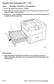
...Duplex Unit Assembly (PL 1.15) Note: The Duplex Unit and Tray 1 are interlocked. 1. The release lever will snap back to lock the Duplex unit in place. Align the guide pins carefully then push down on the guide pins to the locked position when seated properly. 6-154 Phaser 7300 Color Printer Service Manual Holding tray 1, force the duplex... unit backwards about 5 cm and lift the duplex unit to release the Duplex Unit from the paper tray. 7300-188 Reassembly 1. Pull out the Duplex Unit and Tray ...
...Duplex Unit Assembly (PL 1.15) Note: The Duplex Unit and Tray 1 are interlocked. 1. The release lever will snap back to lock the Duplex unit in place. Align the guide pins carefully then push down on the guide pins to the locked position when seated properly. 6-154 Phaser 7300 Color Printer Service Manual Holding tray 1, force the duplex... unit backwards about 5 cm and lift the duplex unit to release the Duplex Unit from the paper tray. 7300-188 Reassembly 1. Pull out the Duplex Unit and Tray ...
Service Manual
Page 195
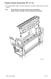
Grasp the Duplex Guide Assembly and pull the assembly straight up and out of the printer. Note: Be careful not to lose the springs when removing the Duplex Guide Assembly. Duplex Guide Assembly (PL 5.1.2) 1. Leave the springs in the printer. . FRU Disassembly S7300-165 6-179
Grasp the Duplex Guide Assembly and pull the assembly straight up and out of the printer. Note: Be careful not to lose the springs when removing the Duplex Guide Assembly. Duplex Guide Assembly (PL 5.1.2) 1. Leave the springs in the printer. . FRU Disassembly S7300-165 6-179
Service Manual
Page 198
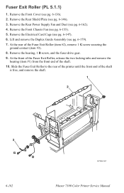
...Fan and Duct (see pg. 6-146). 3. At the rear of the shaft. 10. Remove the Front Chassis Fan (see pg. 6-179). 7. Lift and remove the Duplex Guide Assembly (see pg. 6-155). 5. Remove the bearing, 1 B screw, and the fuser drive gear. 9. Fuser Exit Roller (PL 5.1.1) 1. Remove the Front Cover (see...securing the ground contact (item #3). 8. Remove the Electrical Card Cage (see pg. 6-136). 2. Slide the Fuser Exit Roller to the rear of the printer until the front end of the shaft is free, and remove the shaft. 1 2 3 G B S7300-167 6-182 Phaser 7300 Color Printer Service Manual
...Fan and Duct (see pg. 6-146). 3. At the rear of the shaft. 10. Remove the Front Chassis Fan (see pg. 6-179). 7. Lift and remove the Duplex Guide Assembly (see pg. 6-155). 5. Remove the bearing, 1 B screw, and the fuser drive gear. 9. Fuser Exit Roller (PL 5.1.1) 1. Remove the Front Cover (see...securing the ground contact (item #3). 8. Remove the Electrical Card Cage (see pg. 6-136). 2. Slide the Fuser Exit Roller to the rear of the printer until the front end of the shaft is free, and remove the shaft. 1 2 3 G B S7300-167 6-182 Phaser 7300 Color Printer Service Manual
Service Manual
Page 199
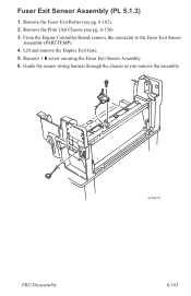
Remove the Print Unit Chassis (see pg. 6-182). 2. Lift and remove the Duplex Exit Gate. 5. Remove 1 B screw securing the Fuser Exit Sensor Assembly. 6. Remove the Fuser Exit Roller (see pg. 6-156). 3. FRU Disassembly S7300-76 6-183 From the Engine Controller Board, remove the connector to the Fuser Exit Sensor Assembly (PARTTEMP). 4. Guide the sensor wiring harness through the chassis as you remove the assembly. Fuser Exit Sensor Assembly (PL 5.1.3) 1.
Remove the Print Unit Chassis (see pg. 6-182). 2. Lift and remove the Duplex Exit Gate. 5. Remove 1 B screw securing the Fuser Exit Sensor Assembly. 6. Remove the Fuser Exit Roller (see pg. 6-156). 3. FRU Disassembly S7300-76 6-183 From the Engine Controller Board, remove the connector to the Fuser Exit Sensor Assembly (PARTTEMP). 4. Guide the sensor wiring harness through the chassis as you remove the assembly. Fuser Exit Sensor Assembly (PL 5.1.3) 1.
Service Manual
Page 211
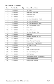
... Side Cover (Door A) Top Fuser Cooling Fan MPT Top Cover Temperature/Humidity Sensor Board Pickup Plate Assembly Pickup Cover Assembly Field Replaceable Units (FRU) Parts List 7-195 Rear Top Cover Damper - FRU Parts List 1.0 - Front Front Cover Duplex Slot Cover Top Cover Damper - Part Number Qty 1 116-0998-00 1 2 116-1061-00 2 3 116...
... Side Cover (Door A) Top Fuser Cooling Fan MPT Top Cover Temperature/Humidity Sensor Board Pickup Plate Assembly Pickup Cover Assembly Field Replaceable Units (FRU) Parts List 7-195 Rear Top Cover Damper - FRU Parts List 1.0 - Front Front Cover Duplex Slot Cover Top Cover Damper - Part Number Qty 1 116-0998-00 1 2 116-1061-00 2 3 116...
Service Manual
Page 219
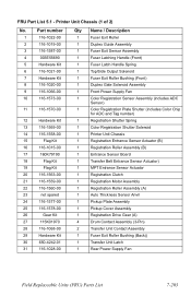
.../Side Output Solenoid 1 Fuser Exit Roller Bushing (Front) 1 Duplex Gate Solenoid Assembly 1 Front Power Supply Fan 1 Color Registration Sensor Assembly (includes ADC Sensor) 1 Color Registration Plate Shutter (includes Color Chip for ADC and Tag number) 1 Registration Shutter Spring 1 Color Registration Shutter Solenoid 1 Printer Unit Chassis 1 Registration Entrance Sensor Actuator (B) 1 Registration Roller Assembly (B) 1 Entrance Sensor Board 1 Transfer Belt Entrance Sensor...
.../Side Output Solenoid 1 Fuser Exit Roller Bushing (Front) 1 Duplex Gate Solenoid Assembly 1 Front Power Supply Fan 1 Color Registration Sensor Assembly (includes ADC Sensor) 1 Color Registration Plate Shutter (includes Color Chip for ADC and Tag number) 1 Registration Shutter Spring 1 Color Registration Shutter Solenoid 1 Printer Unit Chassis 1 Registration Entrance Sensor Actuator (B) 1 Registration Roller Assembly (B) 1 Entrance Sensor Board 1 Transfer Belt Entrance Sensor...
Service Manual
Page 221
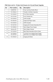
Printer Unit Chassis (2 of 2) and Power Supplies No. 1 2 3 4 5 6 7 8 9 10 11 12 13 Part number 003E55700 116-1556-00 116-1029-00 116-1215-00 116-1034-...-00 116-1064-00 Qty Description 1 Fuser Latching Handle (Rear) 1 Transfer Unit Motor Assembly 1 Front Plate Assembly 1 Front Chassis Fan 1 LVPS Insulator 1 Duplex Exit Paper Guide 1 HVPS Insulator Imaging Unit Contact Assembly (HV) 1 High Voltage Power Supply 1 High Voltage Harness 1 Back Plate Assembly w/Drive Gears 1 (115 VAC) Low Voltage Power Supply 1 (220 VAC) Low Voltage...
Printer Unit Chassis (2 of 2) and Power Supplies No. 1 2 3 4 5 6 7 8 9 10 11 12 13 Part number 003E55700 116-1556-00 116-1029-00 116-1215-00 116-1034-...-00 116-1064-00 Qty Description 1 Fuser Latching Handle (Rear) 1 Transfer Unit Motor Assembly 1 Front Plate Assembly 1 Front Chassis Fan 1 LVPS Insulator 1 Duplex Exit Paper Guide 1 HVPS Insulator Imaging Unit Contact Assembly (HV) 1 High Voltage Power Supply 1 High Voltage Harness 1 Back Plate Assembly w/Drive Gears 1 (115 VAC) Low Voltage Power Supply 1 (220 VAC) Low Voltage...


