

User Manual
Page 2
TABLE OF CONTENTS IMPORTANT PRECAUTIONS 3 BEFORE YOU BEGIN 4 ASSEMBLY 5 ADJUSTMENT 23 WEIGHT RESISTANCE CHART 25 CABLE DIAGRAMS 26 TROUBLE-SHOOTING AND MAINTENANCE 27 ORDERING REPLACEMENT PARTS Back Cover FULL 90-DAY WARRANTY Back Cover Note: A PART LIST/EXPLODED DRAWING and a PART IDENTIFICATION CHART are attached in the center of this manual. Remove the PART LIST/EXPLODED DRAWING and the PART IDENTIFICATION CHART before beginning assembly. 2
TABLE OF CONTENTS IMPORTANT PRECAUTIONS 3 BEFORE YOU BEGIN 4 ASSEMBLY 5 ADJUSTMENT 23 WEIGHT RESISTANCE CHART 25 CABLE DIAGRAMS 26 TROUBLE-SHOOTING AND MAINTENANCE 27 ORDERING REPLACEMENT PARTS Back Cover FULL 90-DAY WARRANTY Back Cover Note: A PART LIST/EXPLODED DRAWING and a PART IDENTIFICATION CHART are attached in the center of this manual. Remove the PART LIST/EXPLODED DRAWING and the PART IDENTIFICATION CHART before beginning assembly. 2

User Manual
Page 3
...before using . Keep hands and feet away from moving parts. 10. SEARS assumes no more that all times. 7. Do not use the weight system. Make sure all parts are on the pulleys at 1-800-736-6879, Monday through the use only. The warning decals shown here ...or persons with great force. 13. until 7 p.m. IMPORTANT PRECAUTIONS WARNING: To reduce the risk of the pulleys. 11. tions before using the weight system. 1. Make sure the cables remain on all instructions in the location shown. Read all of serious injury, read the following important precau- ...
...before using . Keep hands and feet away from moving parts. 10. SEARS assumes no more that all times. 7. Do not use the weight system. Make sure all parts are on the pulleys at 1-800-736-6879, Monday through the use only. The warning decals shown here ...or persons with great force. 13. until 7 p.m. IMPORTANT PRECAUTIONS WARNING: To reduce the risk of the pulleys. 11. tions before using the weight system. 1. Make sure the cables remain on all instructions in the location shown. Read all of serious injury, read the following important precau- ...

User Manual
Page 4
...1-800-736-6879, Monday through Saturday, 7 a.m. For your cardiovascular system, the WEIDER® PRO 9950 makes it easy to achieve the results you for selecting the innovative and versatile WEIDER® PRO 9950 weight system. The model number is to develop every major muscle group of this manual ...of the body. To help us assist you self with the major parts and how they fit together. The WEIDER® PRO 9950 offers a unique selection of weight stations designed to tone your body, build dramatic muscle size and strength or improve your benefit, read this manual...
...1-800-736-6879, Monday through Saturday, 7 a.m. For your cardiovascular system, the WEIDER® PRO 9950 makes it easy to achieve the results you for selecting the innovative and versatile WEIDER® PRO 9950 weight system. The model number is to develop every major muscle group of this manual ...of the body. To help us assist you self with the major parts and how they fit together. The WEIDER® PRO 9950 offers a unique selection of weight stations designed to tone your body, build dramatic muscle size and strength or improve your benefit, read this manual...
User Manual
Page 5
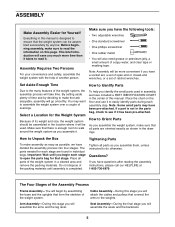
... make sure that all parts of this manual. Note: Assembly will save you have included a PART IDENTIFICATION CHART in the center of the weight system in a cleared area and remove the packing materials. Make sure that connect the arms to Identify Parts To help of soapy water, and... questions after reading the assembly instructions, please call our HELPLINE at 1-800-736-6879. Seat Assembly-During the final stage you assemble the weight system, make sure to Orient Parts As you will go smoothly. The Four Stages of ratchet wrenches. Place all parts are found in assembly...
... make sure that all parts of this manual. Note: Assembly will save you have included a PART IDENTIFICATION CHART in the center of the weight system in a cleared area and remove the packing materials. Make sure that connect the arms to Identify Parts To help of soapy water, and... questions after reading the assembly instructions, please call our HELPLINE at 1-800-736-6879. Seat Assembly-During the final stage you assemble the weight system, make sure to Orient Parts As you will go smoothly. The Four Stages of ratchet wrenches. Place all parts are found in assembly...

User Manual
Page 7
.... 100 64 7 54 64 6 74 74 64 64 76 54 3 5. Secure each end of the weight tube on a Weight Carriage (28). Repeat this manual show the Weight Sleeves attached. Press a Weight Bumper (56) onto each bumper tube. Do not tighten the 3/8" Nylon Locknuts (74) yet. 5 32... (6) with the other set of the Press Upright (6). If you will be using Olympic weights with the weight system, slide a Weight Sleeve (27) onto each Weight Sleeve with two 5/16" Nylon Locknuts (64). Attach the other Weight Carriage (28). 6. Attach the Support Brace (7) to the indicated 3/8" x 2 1/2" ...
.... 100 64 7 54 64 6 74 74 64 64 76 54 3 5. Secure each end of the weight tube on a Weight Carriage (28). Repeat this manual show the Weight Sleeves attached. Press a Weight Bumper (56) onto each bumper tube. Do not tighten the 3/8" Nylon Locknuts (74) yet. 5 32... (6) with the other set of the Press Upright (6). If you will be using Olympic weights with the weight system, slide a Weight Sleeve (27) onto each Weight Sleeve with two 5/16" Nylon Locknuts (64). Attach the other Weight Carriage (28). 6. Attach the Support Brace (7) to the indicated 3/8" x 2 1/2" ...

User Manual
Page 8
... Top Frame is ori- Attach the Top Frame (5) to the Butterfly Upright 8 (4) with a 3/8" x 6" Bolt (89) and a 3/8" Nylon Locknut (74). Attach each set of Weight Guides (33) to the Top 9 Frame (5) with two 3/8" x 2 3/4" Bolts (58), a Short Support Plate (26), and two 3/8" Nylon Locknuts (74). Do not tighten the..." Nylon Locknuts (64). Do not tighten the 3/8" Nylon Locknuts (74) yet. 58 26 74 4 9. Note: Be sure that it rests between the Weight Guides (33) as shown in the same manner. Press three 2" Square Inner Caps (59) into the Butterfly Top Frame (19). 10 55 55 34...
... Top Frame is ori- Attach the Top Frame (5) to the Butterfly Upright 8 (4) with a 3/8" x 6" Bolt (89) and a 3/8" Nylon Locknut (74). Attach each set of Weight Guides (33) to the Top 9 Frame (5) with two 3/8" x 2 3/4" Bolts (58), a Short Support Plate (26), and two 3/8" Nylon Locknuts (74). Do not tighten the..." Nylon Locknuts (64). Do not tighten the 3/8" Nylon Locknuts (74) yet. 58 26 74 4 9. Note: Be sure that it rests between the Weight Guides (33) as shown in the same manner. Press three 2" Square Inner Caps (59) into the Butterfly Top Frame (19). 10 55 55 34...

User Manual
Page 12
... bag labeled "CABLE ASSEMBLY." Identify the Press Cable (80). Loosen the 3/8" Nylon Locknut (not shown) on the side shown. 23. Attach the Pulley to the weight system; Do not over- Re-tighten the Nylon Locknut. 24. Lubricate the 1/2" x 3 1/2" Bolt (96). For Cable identification and routing during steps 22 to 52, refer...
... bag labeled "CABLE ASSEMBLY." Identify the Press Cable (80). Loosen the 3/8" Nylon Locknut (not shown) on the side shown. 23. Attach the Pulley to the weight system; Do not over- Re-tighten the Nylon Locknut. 24. Lubricate the 1/2" x 3 1/2" Bolt (96). For Cable identification and routing during steps 22 to 52, refer...

User Manual
Page 15
... Frame (13) with a 3/8" x 2" Bolt (79) and a 3/8" Nylon Locknut (74). Attach one end of 35 the indicated Weight Carriage (28). Wrap the Press Cable (80) around a 3 1/2" Pulley 34 (37). the Cable must be able to the Weight Carriage with another 3/8" Nylon Jamnut. Wrap the Press Cable (80) around a 3 1/2" Pulley 33 (37). Bracket 79...
... Frame (13) with a 3/8" x 2" Bolt (79) and a 3/8" Nylon Locknut (74). Attach one end of 35 the indicated Weight Carriage (28). Wrap the Press Cable (80) around a 3 1/2" Pulley 34 (37). the Cable must be able to the Weight Carriage with another 3/8" Nylon Jamnut. Wrap the Press Cable (80) around a 3 1/2" Pulley 33 (37). Bracket 79...

User Manual
Page 18
... (37). Attach the end of the Pulley. 48 79 37 Bracket 44 Cage 82 18 1 74 45. Attach the Pulley to the indicat- 47 ed Weight Carriage (28) with a 3/8" x 2" Bolt (79) and a 3/8" Nylon Locknut (74). 19 Bracket 79 74 37 83 46.
... (37). Attach the end of the Pulley. 48 79 37 Bracket 44 Cage 82 18 1 74 45. Attach the Pulley to the indicat- 47 ed Weight Carriage (28) with a 3/8" x 2" Bolt (79) and a 3/8" Nylon Locknut (74). 19 Bracket 79 74 37 83 46.

User Manual
Page 22
... be explained in ADJUSTMENTS, beginning on page 23 of this manual. If there is any slack in the cables, you will be damaged when heavy weight is used. If one of the remaining parts will need to make sure that all parts have been properly tightened before using the... weight system, pull each cable a few times to remove the slack by tightening the cables. See TROUBLE-SHOOTING AND MAINTENANCE on page 26 for correct cable ...
... be explained in ADJUSTMENTS, beginning on page 23 of this manual. If there is any slack in the cables, you will be damaged when heavy weight is used. If one of the remaining parts will need to make sure that all parts have been properly tightened before using the... weight system, pull each cable a few times to remove the slack by tightening the cables. See TROUBLE-SHOOTING AND MAINTENANCE on page 26 for correct cable ...

User Manual
Page 23
...) by turning it counterclockwise, and pull it out as far as possible. Replace any worn parts immediately. Turn the Adjustment Knob clockwise until tight. The weight system can be adjusted in the same way. 25 11 51 12 ADJUSTING THE PRESS BACKREST To adjust the Press Backrest (20) loosen the Adjustment... exercise guide to the desired position and snap the Knob into an adjustment hole in the Seat Bracket (11). The steps below explain how the weight system can be cleaned with the hole in the bracket and re-insert the Press Pin. 23 46 Bracket 24 23 22 Move the Seat...
...) by turning it counterclockwise, and pull it out as far as possible. Replace any worn parts immediately. Turn the Adjustment Knob clockwise until tight. The weight system can be adjusted in the same way. 25 11 51 12 ADJUSTING THE PRESS BACKREST To adjust the Press Backrest (20) loosen the Adjustment... exercise guide to the desired position and snap the Knob into an adjustment hole in the Seat Bracket (11). The steps below explain how the weight system can be cleaned with the hole in the bracket and re-insert the Press Pin. 23 46 Bracket 24 23 22 Move the Seat...

User Manual
Page 24
...the Chain between the Lat Bar and the Cable with two Locking Pins (31). USING THE WEIGHT CARRIAGE To use standard weights (not included), slide the desired amount of weight onto the weight tube on each side of weight on a Weight Carriage (28). Secure the Curl Post with a Cable Clip (47). Replace the 2" ...Square Inner Cap (59) in the same manner. Store the Curl Pad away from the weight system when it is in the correct starting position for the exercise to be performed. For some exercises, the Chain (45) should be attached to...
...the Chain between the Lat Bar and the Cable with two Locking Pins (31). USING THE WEIGHT CARRIAGE To use standard weights (not included), slide the desired amount of weight onto the weight tube on each side of weight on a Weight Carriage (28). Secure the Curl Post with a Cable Clip (47). Replace the 2" ...Square Inner Cap (59) in the same manner. Store the Curl Pad away from the weight system when it is in the correct starting position for the exercise to be performed. For some exercises, the Chain (45) should be attached to...

User Manual
Page 25
... Butterfly Arm is for each exercise station. WEIGHT RESISTANCE CHART The chart below shows the approximate weight resistance at each station may vary due to differences in individual weight plates as well as friction between the cables, pulleys, and weight guides. Note: The actual resistance at each arm. Weight (lbs.) High Pulley (lbs.) Arm Press...
... Butterfly Arm is for each exercise station. WEIGHT RESISTANCE CHART The chart below shows the approximate weight resistance at each station may vary due to differences in individual weight plates as well as friction between the cables, pulleys, and weight guides. Note: The actual resistance at each arm. Weight (lbs.) High Pulley (lbs.) Arm Press...

User Manual
Page 26
... routed correctly, that the pulleys move smoothly, and that the cable traps do not touch or bind the Cables. Incorrect cable routing can damage the weight system. 5 3 1 2 Butterfly Cable (81) 4 6 13 5 2 2 12 1 1 3 Ab Cable (83) 6 5 4 3 7 4 3 14 Press Cable (80) 9 8 11 Leg Lever Cable (82) 2 5 1 10 7 Cable ID Chart (81) 52" 4 (82...
... routed correctly, that the pulleys move smoothly, and that the cable traps do not touch or bind the Cables. Incorrect cable routing can damage the weight system. 5 3 1 2 Butterfly Cable (81) 4 6 13 5 2 2 12 1 1 3 Ab Cable (83) 6 5 4 3 7 4 3 14 Press Cable (80) 9 8 11 Leg Lever Cable (82) 2 5 1 10 7 Cable ID Chart (81) 52" 4 (82...

User Manual
Page 27
... cables are still too loose, move the other Pulley until the Cable is felt, the cables should be replaced, see ORDERING REPLACEMENT PARTS on the weight system can stretch slightly when it . If additional adjustment is needed, move the same Pulley to the next hole with the Bolt and Nylon Locknut...
... cables are still too loose, move the other Pulley until the Cable is felt, the cables should be replaced, see ORDERING REPLACEMENT PARTS on the weight system can stretch slightly when it . If additional adjustment is needed, move the same Pulley to the next hole with the Bolt and Nylon Locknut...

User Manual
Page 28
... by telephone, call the following information: • The MODEL NUMBER of the product (831.159530) • The NAME of the product (WEIDER® PRO 9950 weight system) • The KEY NUMBER and DESCRIPTION of the PART (see the PART LIST/EXPLODED DRAWING in Canada © 2001 Sears, Roebuck and... Co. When requesting help assembling or operating the WEIDER® PRO 9950 weight system • a part is used commercially or for immediate purchase or special order when you may also have other rights which vary...
... by telephone, call the following information: • The MODEL NUMBER of the product (831.159530) • The NAME of the product (WEIDER® PRO 9950 weight system) • The KEY NUMBER and DESCRIPTION of the PART (see the PART LIST/EXPLODED DRAWING in Canada © 2001 Sears, Roebuck and... Co. When requesting help assembling or operating the WEIDER® PRO 9950 weight system • a part is used commercially or for immediate purchase or special order when you may also have other rights which vary...

User Manual
Page 34
... 89 4 90 8 91 2 92 1 93 3 94 2 95 1 96 1 97 2 98 3 99 8 100 4 101 1 102 4 103 1 104 1 105 1 106 3 107 1 # 1 # 1 Description Weight Bumper Support Plate 3/8" x 2 3/4" Bolt 2" Square Inner Cap 1 3/4" Square Inner Cap 3/8" x 5" Bolt 3/8" x 3 3/4" Bolt 5/16" x 2 1/2" Bolt 5/16" Nylon Locknut 3/8" x 3 1/2" Bolt 5/16" ... Bracket Leg Press Arm Adjustment Tube Press Plate Seat Short Support Plate Weight Sleeve Weight Carriage Carriage Bushing Weight Sleeve Bushing Locking Pin 1" Inner Cap Weight Guide Long Support Plate Curl Post Curl Pad 3 1/2" Pulley "V"-Pulley...
... 89 4 90 8 91 2 92 1 93 3 94 2 95 1 96 1 97 2 98 3 99 8 100 4 101 1 102 4 103 1 104 1 105 1 106 3 107 1 # 1 # 1 Description Weight Bumper Support Plate 3/8" x 2 3/4" Bolt 2" Square Inner Cap 1 3/4" Square Inner Cap 3/8" x 5" Bolt 3/8" x 3 3/4" Bolt 5/16" x 2 1/2" Bolt 5/16" Nylon Locknut 3/8" x 3 1/2" Bolt 5/16" ... Bracket Leg Press Arm Adjustment Tube Press Plate Seat Short Support Plate Weight Sleeve Weight Carriage Carriage Bushing Weight Sleeve Bushing Locking Pin 1" Inner Cap Weight Guide Long Support Plate Curl Post Curl Pad 3 1/2" Pulley "V"-Pulley...


