
English Manual
Page 2
... Cable Diagram 19 Adjustment 20 Weight Resistance Chart 22 Trouble-shooting and Maintenance 23 Ordering Replacement Parts Back Cover Full 90 Day Warranty Back Cover Note: A PART LIST/EXPLODED DRAWING and a PART IDENTIFICATION CHART are attached to the center of 12 and pets away from the home gym ...on a foot plate when performing an exercise that does not use of 35 or persons with great force. 5. Remove the PART LIST/EXPLODED DRAWING and the PART IDENTIFICATION CHART before using . The home gym system is the responsibility of the owner to ensure that all precautions. 2. Always...
... Cable Diagram 19 Adjustment 20 Weight Resistance Chart 22 Trouble-shooting and Maintenance 23 Ordering Replacement Parts Back Cover Full 90 Day Warranty Back Cover Note: A PART LIST/EXPLODED DRAWING and a PART IDENTIFICATION CHART are attached to the center of 12 and pets away from the home gym ...on a foot plate when performing an exercise that does not use of 35 or persons with great force. 5. Remove the PART LIST/EXPLODED DRAWING and the PART IDENTIFICATION CHART before using . The home gym system is the responsibility of the owner to ensure that all precautions. 2. Always...
English Manual
Page 3
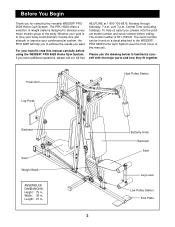
... note the product model number and serial number before using the WEIDER® PRO 9628 Home Gym System. Length: 91 in . For your cardiovascular system, the PRO 9628 will help us assist you want. The model number is to the WEIDER® PRO 9628 Home Gym System (see the front cover of the body. ...muscle group of this manual carefully before calling. Butterfly Arms Backrest Seat Leg Lever Low Pulley Station Foot Plate 3 until 7 p.m. The PRO 9628 offers a selection of weight stations designed to familiarize yourself with the major parts and how they fit together.
... note the product model number and serial number before using the WEIDER® PRO 9628 Home Gym System. Length: 91 in . For your cardiovascular system, the PRO 9628 will help us assist you want. The model number is to the WEIDER® PRO 9628 Home Gym System (see the front cover of the body. ...muscle group of this manual carefully before calling. Butterfly Arms Backrest Seat Leg Lever Low Pulley Station Foot Plate 3 until 7 p.m. The PRO 9628 offers a selection of weight stations designed to familiarize yourself with the major parts and how they fit together.
English Manual
Page 4
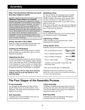
...begin each step. Place all the way around the assembled equipment. Cable Assembly Completes the cables and pulleys that connect the moving parts will be attached to make the assembly process as smooth as a unit Arm Assembly Completes the press and butterfly arms that support...8226; One (1) rubber mallet • Lubricant, such as grease or petroleum jelly, and soapy water • Tape, such as you open the parts bag labeled for each assembly stage to complete the steps outlined here. Clearing the Workspace Clear a workspace that is a sophisticated product with the weights....
...begin each step. Place all the way around the assembled equipment. Cable Assembly Completes the cables and pulleys that connect the moving parts will be attached to make the assembly process as smooth as a unit Arm Assembly Completes the press and butterfly arms that support...8226; One (1) rubber mallet • Lubricant, such as grease or petroleum jelly, and soapy water • Tape, such as you open the parts bag labeled for each assembly stage to complete the steps outlined here. Clearing the Workspace Clear a workspace that is a sophisticated product with the weights....
English Manual
Page 5
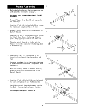
... flat on top of the 2 Butterfly Base (4). Press a 2" Square Inner Cap (27) into the end of the mounting bracket on page 4. 5 Locate and open the parts bag labeled "FRAME 78 ASSEMBLY."
... flat on top of the 2 Butterfly Base (4). Press a 2" Square Inner Cap (27) into the end of the mounting bracket on page 4. 5 Locate and open the parts bag labeled "FRAME 78 ASSEMBLY."
English Manual
Page 8
... (17). Press a 2" Square Inner Cap (27) into the Press Seat Frame (77). Note: This will be a tight fit. Press Arm Assembly-Locate and open the parts bag labeled "ARM ASSEMBLY."
... (17). Press a 2" Square Inner Cap (27) into the Press Seat Frame (77). Note: This will be a tight fit. Press Arm Assembly-Locate and open the parts bag labeled "ARM ASSEMBLY."

English Manual
Page 10
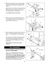
... pre-assembled Pulley (15) on the Top Frame (55) Attach a "V"-Pulley (6) and a Long Cable Trap (50) to the inset drawing. 16. Locate and open the parts bag labeled "Cable 18 Assembly and Pulleys." A Tap two 1" Retainers (69) and a 1" Round Cover Cap (70) onto the right axle. Refer to the indicated bracket...
... pre-assembled Pulley (15) on the Top Frame (55) Attach a "V"-Pulley (6) and a Long Cable Trap (50) to the inset drawing. 16. Locate and open the parts bag labeled "Cable 18 Assembly and Pulleys." A Tap two 1" Retainers (69) and a 1" Round Cover Cap (70) onto the right axle. Refer to the indicated bracket...
English Manual
Page 15
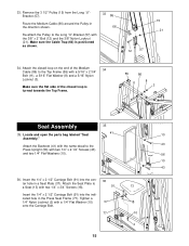
... 1/4" Flat Washers (10). 56 10 43 36. 33. Attach the Seat Plate to the Long "U"-Bracket (57) with two 1/4" x 3/4" Screws (18). Locate and open the parts bag labeled "Seat 41 10 Assembly." Make sure the Cable Trap (66) is turned towards the Top Frame. 55 86 8 11 3 Seat Assembly 35 35...
... 1/4" Flat Washers (10). 56 10 43 36. 33. Attach the Seat Plate to the Long "U"-Bracket (57) with two 1/4" x 3/4" Screws (18). Locate and open the parts bag labeled "Seat 41 10 Assembly." Make sure the Cable Trap (66) is turned towards the Top Frame. 55 86 8 11 3 Seat Assembly 35 35...
English Manual
Page 19
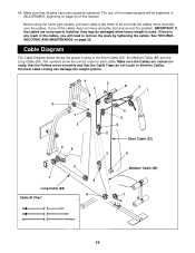
... are not properly installed, they may be damaged when heavy weight is any slack in ADJUSTMENT, beginning on page 22. The use of the remaining parts will need to be explained in the cables, you will be sure that the Cable Traps do not touch or bind the Cables. If one... and that the cables move smoothly, find and correct the problem. See TROUBLESHOOTING AND MAINTENANCE on page 20 of this manual. Make sure that all parts have been properly tightened. 46.
... are not properly installed, they may be damaged when heavy weight is any slack in ADJUSTMENT, beginning on page 22. The use of the remaining parts will need to be explained in the cables, you will be sure that the Cable Traps do not touch or bind the Cables. If one... and that the cables move smoothly, find and correct the problem. See TROUBLESHOOTING AND MAINTENANCE on page 20 of this manual. Make sure that all parts have been properly tightened. 46.
English Manual
Page 20
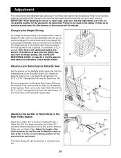
Adjustment The instructions below describe how each part of the Weight Pin is touching the Weights, and turn the bent end downward. Be sure to the cables and pulleys, the amount of the ...
Adjustment The instructions below describe how each part of the Weight Pin is touching the Weights, and turn the bent end downward. Be sure to the cables and pulleys, the amount of the ...
English Manual
Page 23
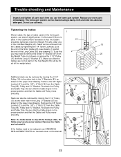
...the Cable and re-install it is felt, the Cables should be cleaned using a damp cloth and mild non-abrasive detergent. Replace any worn parts immediately. Do not use the home gym system. Slack can also be replaced, see drawing 2). Tightening the Cables 1 Woven cable, the type ...Cable (23) (see drawing 1) and at the end of the Long Cable (58) (see ORDERING REPLACEMENT PARTS on the home gym system, can be tightened. Trouble-shooting and Maintenance Inspect and tighten all parts each time you may have become twisted. Remove the 3/8" Nylon Locknut (21) and the 3/8" x 2" ...
...the Cable and re-install it is felt, the Cables should be cleaned using a damp cloth and mild non-abrasive detergent. Replace any worn parts immediately. Do not use the home gym system. Slack can also be replaced, see drawing 2). Tightening the Cables 1 Woven cable, the type ...Cable (23) (see drawing 1) and at the end of the Long Cable (58) (see ORDERING REPLACEMENT PARTS on the home gym system, can be tightened. Trouble-shooting and Maintenance Inspect and tighten all parts each time you may have become twisted. Remove the 3/8" Nylon Locknut (21) and the 3/8" x 2" ...
English Manual
Page 26
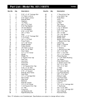
... 1 Leg Press Arm 90 1 Lock Pin 91 1 1/4" x 2 1/2" Carriage Bolt 92 1 1" Tap Screw 93 2 3/8" x 2 3/4" Bolt 94 2 3/8" x 2 3/4" Carriage Bolt # 1 User's Manual # 1 Exercise Poster Note: "#" indicates a non-illustrated part. Description Key No. Qty. Part List-Model No. 831.159370 R0998A Key No. Qty. Specifications are subject to change without notice.
... 1 Leg Press Arm 90 1 Lock Pin 91 1 1/4" x 2 1/2" Carriage Bolt 92 1 1" Tap Screw 93 2 3/8" x 2 3/4" Bolt 94 2 3/8" x 2 3/4" Carriage Bolt # 1 User's Manual # 1 Exercise Poster Note: "#" indicates a non-illustrated part. Description Key No. Qty. Part List-Model No. 831.159370 R0998A Key No. Qty. Specifications are subject to change without notice.
English Manual
Page 28
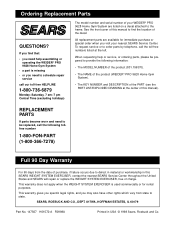
...warranty does not apply when the WEIGHT SYSTEM EXERCISER is missing • or you visit your WEIDER® PRO 9628 Home Gym System are available for rental purposes. REPLACEMENT PARTS If parts become worn and need to defect in material or workmanship in USA © 1998 Sears, ...831.159370). • The NAME of the product (WEIDER® PRO 9628 Home Gym System). • The KEY NUMBER and DESCRIPTION of charge. When requesting help assembling or operating the WEIDER® PRO 9628 Home Gym System • a part is used commercially or for immediate purchase or special order...
...warranty does not apply when the WEIGHT SYSTEM EXERCISER is missing • or you visit your WEIDER® PRO 9628 Home Gym System are available for rental purposes. REPLACEMENT PARTS If parts become worn and need to defect in material or workmanship in USA © 1998 Sears, ...831.159370). • The NAME of the product (WEIDER® PRO 9628 Home Gym System). • The KEY NUMBER and DESCRIPTION of charge. When requesting help assembling or operating the WEIDER® PRO 9628 Home Gym System • a part is used commercially or for immediate purchase or special order...


