
English Manual
Page 1
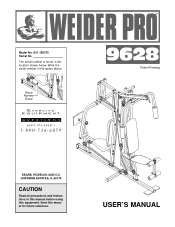
Save this equipment. Serial Number Decal ® Patent Pending SEARS, ROEBUCK AND CO. Write the serial number in the location shown below. HOFFMAN ESTATES, IL 60179 CAUTION Read all precautions and instructions in this manual before using this manual for future reference. The serial number is found in the space above. USER'S MANUAL Model No. 831.159370 Serial No.
Save this equipment. Serial Number Decal ® Patent Pending SEARS, ROEBUCK AND CO. Write the serial number in the location shown below. HOFFMAN ESTATES, IL 60179 CAUTION Read all precautions and instructions in this manual before using this manual for future reference. The serial number is found in the space above. USER'S MANUAL Model No. 831.159370 Serial No.
English Manual
Page 2
... You Begin 3 Assembly 4 Cable Diagram 19 Adjustment 20 Weight Resistance Chart 22 Trouble-shooting and Maintenance 23 Ordering Replacement Parts Back Cover Full 90 Day Warranty Back Cover Note: A PART LIST/EXPLODED DRAWING and a PART IDENTIFICATION CHART are raised. Read all parts often. If you are exercising, stop immediately and begin cooling down over the age of this manual. Never release the Press Arm, Butterfly Arms, Leg Lever, Lat Bar or Nylon Strap while Weights are attached to be used by or...
... You Begin 3 Assembly 4 Cable Diagram 19 Adjustment 20 Weight Resistance Chart 22 Trouble-shooting and Maintenance 23 Ordering Replacement Parts Back Cover Full 90 Day Warranty Back Cover Note: A PART LIST/EXPLODED DRAWING and a PART IDENTIFICATION CHART are raised. Read all parts often. If you are exercising, stop immediately and begin cooling down over the age of this manual. Never release the Press Arm, Butterfly Arms, Leg Lever, Lat Bar or Nylon Strap while Weights are attached to be used by or...
English Manual
Page 3
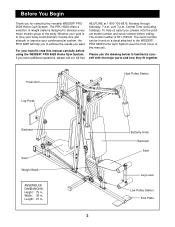
The PRO 9628 offers a selection of weight stations designed to the WEIDER® PRO 9628 Home Gym System (see the front cover of the body. If you for selecting the versatile WEIDER® PRO 9628 Home Gym System. The serial number can be found on a decal attached to develop every major muscle group of this manual carefully before calling. Press Arm High Pulley Station Leg Press Backrest Seat Weight Stack ASSEMBLED DIMENSIONS: Height: 79 in . Central Time (excluding holidays...
The PRO 9628 offers a selection of weight stations designed to the WEIDER® PRO 9628 Home Gym System (see the front cover of the body. If you for selecting the versatile WEIDER® PRO 9628 Home Gym System. The serial number can be found on a decal attached to develop every major muscle group of this manual carefully before calling. Press Arm High Pulley Station Leg Press Backrest Seat Weight Stack ASSEMBLED DIMENSIONS: Height: 79 in . Central Time (excluding holidays...
English Manual
Page 4
... the seats and backrests that you operate while you identify the small parts used in assembly, we have a socket set, a set of open-end or closed-end wrenches or a set of the equipment. Assembly Note: This introduction will take the time to recognize that the assembly of the packing materials until you assemble them, unless instructed to open the packages for that connect the moving parts...
... the seats and backrests that you operate while you identify the small parts used in assembly, we have a socket set, a set of open-end or closed-end wrenches or a set of the equipment. Assembly Note: This introduction will take the time to recognize that the assembly of the packing materials until you assemble them, unless instructed to open the packages for that connect the moving parts...
English Manual
Page 7
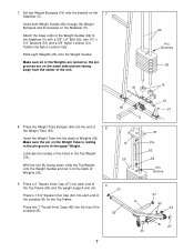
... the upper Weight. 7. Attach the lower ends of 8 the Weight Tube (63). Lubricate the insides of the unit. 62 Pin Grooves 25 19 61 8. With the slot (B) facing down, slide the Top Weight onto the Weight Guides and set it on the 7 Stabilizer (5). Press a 2" Square Inner Cap (27) into each end of 9 the Top Frame (55) and the weight support arm (A). 27 Press a 1 3/4" Square Inner...
... the upper Weight. 7. Attach the lower ends of 8 the Weight Tube (63). Lubricate the insides of the unit. 62 Pin Grooves 25 19 61 8. With the slot (B) facing down, slide the Top Weight onto the Weight Guides and set it on the 7 Stabilizer (5). Press a 2" Square Inner Cap (27) into each end of 9 the Top Frame (55) and the weight support arm (A). 27 Press a 1 3/4" Square Inner...
English Manual
Page 8
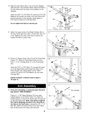
... the Uprights. Insert two 5/16" x 2 3/4" Bolts (11) through the bracket on the Top Frame (55). Press Arm Assembly-Locate and open the parts bag labeled "ARM ASSEMBLY." Note: This will be a tight fit. 10. Place the Top Frame (55) on top of the Weight Guides (62) to the Top Frame with the tube (A) on the Seat Frame and through the holes in the direction shown...
... the Uprights. Insert two 5/16" x 2 3/4" Bolts (11) through the bracket on the Top Frame (55). Press Arm Assembly-Locate and open the parts bag labeled "ARM ASSEMBLY." Note: This will be a tight fit. 10. Place the Top Frame (55) on top of the Weight Guides (62) to the Top Frame with the tube (A) on the Seat Frame and through the holes in the direction shown...

English Manual
Page 10
... 89 the Leg Press Arm (89). 27 21 Lubricate the 3/8" x 3 1/4" Bolt (85). Attach the Bumper (82) to 17 the Press Seat Frame (77) with the Bolt and a 3/8" Nylon Locknut (21). 92 82 77 Cable Assembly 85 Lubricate 27 77 51 18. Note: Be careful not to the inset drawing. For Cable identification and routing during steps 18-35, refer to the Cable 50 Diagram and Cable ID Chart on...
... 89 the Leg Press Arm (89). 27 21 Lubricate the 3/8" x 3 1/4" Bolt (85). Attach the Bumper (82) to 17 the Press Seat Frame (77) with the Bolt and a 3/8" Nylon Locknut (21). 92 82 77 Cable Assembly 85 Lubricate 27 77 51 18. Note: Be careful not to the inset drawing. For Cable identification and routing during steps 18-35, refer to the Cable 50 Diagram and Cable ID Chart on...
English Manual
Page 11
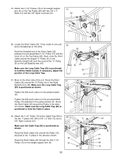
... Upright (42) and then around the "V"-Pulley (6) on the pre-assembled Pulley (15) attached to hold the Cable in the direc- D Tighten the Bolt and Locknut on the Right Butterfly Arm (48). Route the Short Cable (23) around the Pulley in place. tion shown. Make sure the Cable Trap (66) is positioned to hold the Cable in the direction shown. Tighten the Bolt and Locknut on the weight support arm...
... Upright (42) and then around the "V"-Pulley (6) on the pre-assembled Pulley (15) attached to hold the Cable in the direc- D Tighten the Bolt and Locknut on the Right Butterfly Arm (48). Route the Short Cable (23) around the Pulley in place. tion shown. Make sure the Cable Trap (66) is positioned to hold the Cable in the direction shown. Tighten the Bolt and Locknut on the weight support arm...
English Manual
Page 12
... (67) with a 3/8" x 3 3/4" Bolt (71), a 3/8" Flat Washer (9) and a 3/8" Nylon Jam Nut (83). It should be threaded onto the end of the Cable only a couple of all Pulleys and that the Cable and the Pulleys move smoothly. Attach a "V"-Pulley (6) and a Long Cable Trap (50) to the lower end of the Upright and that the Long Cable Trap is on the weight support arm. Attach a 3 1/2" Pulley (15) and a Cable Trap (66...
... (67) with a 3/8" x 3 3/4" Bolt (71), a 3/8" Flat Washer (9) and a 3/8" Nylon Jam Nut (83). It should be threaded onto the end of the Cable only a couple of all Pulleys and that the Cable and the Pulleys move smoothly. Attach a "V"-Pulley (6) and a Long Cable Trap (50) to the lower end of the Upright and that the Long Cable Trap is on the weight support arm. Attach a 3 1/2" Pulley (15) and a Cable Trap (66...

English Manual
Page 13
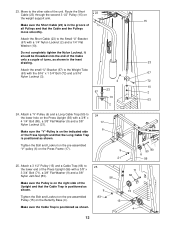
... the Press Upright (56) in the direction shown. Route the Long Cable around the "V"-Pulley (6) on the Press Seat Frame (77) in the direction 22 6 shown. Make sure the Long Cable Trap is attached on the indi- 58 cated side of the Press Upright. 8 Route the threaded end of the closed loop to place the Long Cable Trap on the Press Seat Frame (77) with a 5/16" x 2 3/4" Bolt (11...
... the Press Upright (56) in the direction shown. Route the Long Cable around the "V"-Pulley (6) on the Press Seat Frame (77) in the direction 22 6 shown. Make sure the Long Cable Trap is attached on the indi- 58 cated side of the Press Upright. 8 Route the threaded end of the closed loop to place the Long Cable Trap on the Press Seat Frame (77) with a 5/16" x 2 3/4" Bolt (11...

English Manual
Page 14
Route the Long Cable (58) around the second 3 1/2" Pulley (15) on the Leg Press Arm (89) in the direction shown. 89 15 30. 29. Attach the Long Cable to the other . It has a closed loop 31 on one end and a ball on the Butterfly Base (4). Move to the Long "U"-Bracket (57) with a 3/8" x 3 3/4" Bolt (71), a 3/8" Flat Washer (9) and a 3/8" Nylon Jam Nut (83). 58...
Route the Long Cable (58) around the second 3 1/2" Pulley (15) on the Leg Press Arm (89) in the direction shown. 89 15 30. 29. Attach the Long Cable to the other . It has a closed loop 31 on one end and a ball on the Butterfly Base (4). Move to the Long "U"-Bracket (57) with a 3/8" x 3 3/4" Bolt (71), a 3/8" Flat Washer (9) and a 3/8" Nylon Jam Nut (83). 58...
English Manual
Page 15
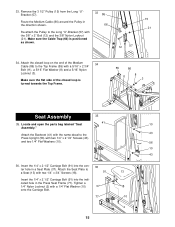
Make sure the Cable Trap (66) is turned towards the Top Frame. 55 86 8 11 3 Seat Assembly 35 35. Locate and open the parts bag labeled "Seat 41 10 Assembly." Insert the 1/4" x 2 1/2" Carriage Bolt (91) into the indicated hole in the Press Seat Frame (77). Tighten a 1/4" Nylon Locknut (2) with two 1/4" x 2 1/2" Screws (43) and two 1/4" Flat Washers (10). 56 10 43 36. Attach the closed loop is...
Make sure the Cable Trap (66) is turned towards the Top Frame. 55 86 8 11 3 Seat Assembly 35 35. Locate and open the parts bag labeled "Seat 41 10 Assembly." Insert the 1/4" x 2 1/2" Carriage Bolt (91) into the indicated hole in the Press Seat Frame (77). Tighten a 1/4" Nylon Locknut (2) with two 1/4" x 2 1/2" Screws (43) and two 1/4" Flat Washers (10). 56 10 43 36. Attach the closed loop is...

English Manual
Page 17
... (88). 87 22 17 88 3 44 8 Insert one Pad Tube into the Leg Lever (29). Rest the Butterfly Seat Frame (36) on the indicated pin (A) in the Butterfly Upright (42). Leg Press Assembly Attach the Leg Press Plate (87) to the Butterfly Upright with the Bolt and a 5/16" Nylon Locknut (3). Slide a Foam Pad (30) onto each end of the Pad Tube. 14...
... (88). 87 22 17 88 3 44 8 Insert one Pad Tube into the Leg Lever (29). Rest the Butterfly Seat Frame (36) on the indicated pin (A) in the Butterfly Upright (42). Leg Press Assembly Attach the Leg Press Plate (87) to the Butterfly Upright with the Bolt and a 5/16" Nylon Locknut (3). Slide a Foam Pad (30) onto each end of the Pad Tube. 14...
English Manual
Page 19
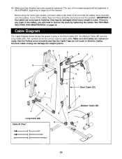
... use of this manual. IMPORTANT: If the cables are routed correctly, that the Pulleys move smoothly and that the cables move smoothly, find and correct the problem. The numbers show the correct route for each cable a few times to remove the slack by tightening the cables. If there is any slack in ADJUSTMENT, beginning on page 22. See TROUBLESHOOTING AND MAINTENANCE on page 20 of the remaining parts will need...
... use of this manual. IMPORTANT: If the cables are routed correctly, that the Pulleys move smoothly and that the cables move smoothly, find and correct the problem. The numbers show the correct route for each cable a few times to remove the slack by tightening the cables. If there is any slack in ADJUSTMENT, beginning on page 22. See TROUBLESHOOTING AND MAINTENANCE on page 20 of the remaining parts will need...
English Manual
Page 20
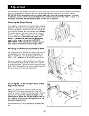
.... Changing the Weight Setting To change the weight setting of resistance at each exercise. For some exercises, the Butterfly Seat Frame (36) must be attached between the Lat Bar and the Medium Cable so the Lat Bar is not attached to insert the Weight Pin until the bent end of the Weight Pin is performed, the effectiveness of the exercise will be adjusted. Be sure to the leg lever. Use the WEIGHT 25 RESISTANCE CHART on the Butterfly Upright...
.... Changing the Weight Setting To change the weight setting of resistance at each exercise. For some exercises, the Butterfly Seat Frame (36) must be attached between the Lat Bar and the Medium Cable so the Lat Bar is not attached to insert the Weight Pin until the bent end of the Weight Pin is performed, the effectiveness of the exercise will be adjusted. Be sure to the leg lever. Use the WEIGHT 25 RESISTANCE CHART on the Butterfly Upright...

English Manual
Page 21
... Butterfly upright (see ATTACHING AND REMOVING THE BUTTERFLY SEAT on page 20). Move the Adjustment Tube (88) to the 88 desired position and re-insert the Lock Pin. 90 21 Attaching the Leg Lever to the Low Pulley Station To use the Leg Lever (29), the seat must be attached in the correct starting position for the exercise to be attached between the Lat Bar and the Long Cable with a Cable...
... Butterfly upright (see ATTACHING AND REMOVING THE BUTTERFLY SEAT on page 20). Move the Adjustment Tube (88) to the 88 desired position and re-insert the Lock Pin. 90 21 Attaching the Leg Lever to the Low Pulley Station To use the Leg Lever (29), the seat must be attached in the correct starting position for the exercise to be attached between the Lat Bar and the Long Cable with a Cable...

English Manual
Page 22
... Low Pulley (lbs.) 7 17 30 43 58 68 83 95 107 22 The other numbers refer to the 6.5 lbs. "Top" refers to the 12.5 lbs. Note: The actual resistance at each weight station may vary due to differences in individual weight plates, as well as friction between the cables, pulleys, and weight guides. weight plates. Weight Resistance Chart This chart shows the approximate weight resistance at...
... Low Pulley (lbs.) 7 17 30 43 58 68 83 95 107 22 The other numbers refer to the 6.5 lbs. "Top" refers to the 12.5 lbs. Note: The actual resistance at each weight station may vary due to differences in individual weight plates, as well as friction between the cables, pulleys, and weight guides. weight plates. Weight Resistance Chart This chart shows the approximate weight resistance at...
English Manual
Page 23
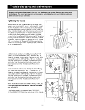
Trouble-shooting and Maintenance Inspect and tighten all parts each time you may have become twisted. Insert the Weight Pin (26) under one of cable used . Make sure that the Cables are not too tight or the Top Weight (76) will be lifted off the Pulleys often, the Cable may need to be removed from the Long "U"-Bracket (57). Re-attach the Pulley and Cable Trap. Be sure...
Trouble-shooting and Maintenance Inspect and tighten all parts each time you may have become twisted. Insert the Weight Pin (26) under one of cable used . Make sure that the Cables are not too tight or the Top Weight (76) will be lifted off the Pulleys often, the Cable may need to be removed from the Long "U"-Bracket (57). Re-attach the Pulley and Cable Trap. Be sure...
English Manual
Page 26
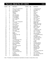
...Plastic Bushing 75 2 1" x 7/8" Plastic Bushing 76 1 Top Weight 77 1 Press Seat Frame 78 2 2" Square Cover Cap 79 1 3/8" x 4 1/2" Bolt 80 1 3/8" x 4 1/4" Bolt 81 2 "I"-Plate 82 1 Bumper 83 5 3/8" Nylon Jam Nut 84 2 Leg Press Bushing 85 1 3/8" x 3 1/4" Bolt 86 1 Medium Cable 87 1 Leg Press Plate 88 1 Adjustment Tube 89 1 Leg Press Arm 90 1 Lock Pin 91 1 1/4" x 2 1/2" Carriage Bolt 92 1 1" Tap Screw 93 2 3/8" x 2 3/4" Bolt 94 2 3/8" x 2 3/4" Carriage Bolt # 1 User's Manual # 1 Exercise Poster Note: "#" indicates a non-illustrated...
...Plastic Bushing 75 2 1" x 7/8" Plastic Bushing 76 1 Top Weight 77 1 Press Seat Frame 78 2 2" Square Cover Cap 79 1 3/8" x 4 1/2" Bolt 80 1 3/8" x 4 1/4" Bolt 81 2 "I"-Plate 82 1 Bumper 83 5 3/8" Nylon Jam Nut 84 2 Leg Press Bushing 85 1 3/8" x 3 1/4" Bolt 86 1 Medium Cable 87 1 Leg Press Plate 88 1 Adjustment Tube 89 1 Leg Press Arm 90 1 Lock Pin 91 1 1/4" x 2 1/2" Carriage Bolt 92 1 1" Tap Screw 93 2 3/8" x 2 3/4" Bolt 94 2 3/8" x 2 3/4" Carriage Bolt # 1 User's Manual # 1 Exercise Poster Note: "#" indicates a non-illustrated...
English Manual
Page 28
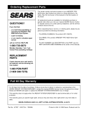
... WEIGHT SYSTEM EXERCISER, free of the PART (see the PART LIST/EXPLODED DRAWING at the left. When requesting help assembling or operating the WEIDER® PRO 9628 Home Gym System • a part is used commercially or for immediate purchase or special order when you need to be prepared to defect in material or workmanship in USA © 1998 Sears, Roebuck and Co. If you find the location...
... WEIGHT SYSTEM EXERCISER, free of the PART (see the PART LIST/EXPLODED DRAWING at the left. When requesting help assembling or operating the WEIDER® PRO 9628 Home Gym System • a part is used commercially or for immediate purchase or special order when you need to be prepared to defect in material or workmanship in USA © 1998 Sears, Roebuck and Co. If you find the location...


