
English Manual
Page 2
... 12 and pets away from the home gym system at a time. 3. Table of Contents Important Precautions 2 Before You Begin 3 Assembly 4 Cable Diagram 19 Adjustment 20 Weight Resistance Chart 22 Trouble-shooting and Maintenance 23 Ordering Replacement Parts Back Cover Full 90 Day Warranty Back Cover Note... the accompanying literature before using the home gym system. 8. This is the responsibility of the owner to tip. 15. Make sure the Cables remain on all parts often. Never release the Press Arm, Butterfly Arms, Leg Lever, Lat Bar or Nylon Strap while Weights are on...
... 12 and pets away from the home gym system at a time. 3. Table of Contents Important Precautions 2 Before You Begin 3 Assembly 4 Cable Diagram 19 Adjustment 20 Weight Resistance Chart 22 Trouble-shooting and Maintenance 23 Ordering Replacement Parts Back Cover Full 90 Day Warranty Back Cover Note... the accompanying literature before using the home gym system. 8. This is the responsibility of the owner to tip. 15. Make sure the Cables remain on all parts often. Never release the Press Arm, Butterfly Arms, Leg Lever, Lat Bar or Nylon Strap while Weights are on...
English Manual
Page 4
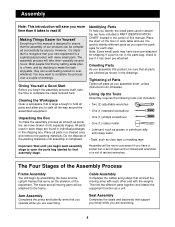
...): • Two (2) adjustable wrenches • One (1) standard screwdriver Unpacking the Box To make the task enjoyable, they can avoid feeling rushed or overwhelmed. Cable Assembly Completes the cables and pulleys that you operate while you to walk all parts and allow you are found in individual packages in the parts bag, check...
...): • Two (2) adjustable wrenches • One (1) standard screwdriver Unpacking the Box To make the task enjoyable, they can avoid feeling rushed or overwhelmed. Cable Assembly Completes the cables and pulleys that you operate while you to walk all parts and allow you are found in individual packages in the parts bag, check...

English Manual
Page 9
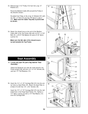
Butterfly Arm Assembly Attach a "V"-Pulley (6) and a Long Cable Trap (50) to the Press Frame (17) with a 3/8" x 2 1/2" Bolt (7) and a 3/8" Nylon Locknut (21). Note the position of each Press Arm (46). Press a 1" Round Inner Cap (... Butterfly Arm (47) and (48) with two 5/16" x 2 1/2" Bolts (22) and two 5/16" Nylon Locknuts (3). 17 22 3 46 49 44 15. Make sure the Long Cable Traps (50) are positioned as shown.
Butterfly Arm Assembly Attach a "V"-Pulley (6) and a Long Cable Trap (50) to the Press Frame (17) with a 3/8" x 2 1/2" Bolt (7) and a 3/8" Nylon Locknut (21). Note the position of each Press Arm (46). Press a 1" Round Inner Cap (... Butterfly Arm (47) and (48) with two 5/16" x 2 1/2" Bolts (22) and two 5/16" Nylon Locknuts (3). 17 22 3 46 49 44 15. Make sure the Long Cable Traps (50) are positioned as shown.

English Manual
Page 10
...." Attach the Bumper (82) to the indicated bracket (A) on the Retainers (69) bend toward the Cover Cap (70), as shown, so it will hold the Cable in the same manner. 55 47 B 69 70 44 Press a 1 3/4" Square Inner Cap (44) into each Arm (47) and (48). Press a 2" Square ... Chart on page 19. 55 6 Tighten the Bolt and Locknut on the pre-assembled Pulley (15) on the Top Frame (55) Attach a "V"-Pulley (6) and a Long Cable Trap (50) to 17 the Press Seat Frame (77) with a 3/8" x 2 1/2" Bolt (7) and a 3/8" Nylon Locknut (21). A Tap two 1" Retainers (69) and a 1" Round Cover Cap ...
...." Attach the Bumper (82) to the indicated bracket (A) on the Retainers (69) bend toward the Cover Cap (70), as shown, so it will hold the Cable in the same manner. 55 47 B 69 70 44 Press a 1 3/4" Square Inner Cap (44) into each Arm (47) and (48). Press a 2" Square ... Chart on page 19. 55 6 Tighten the Bolt and Locknut on the pre-assembled Pulley (15) on the Top Frame (55) Attach a "V"-Pulley (6) and a Long Cable Trap (50) to 17 the Press Seat Frame (77) with a 3/8" x 2 1/2" Bolt (7) and a 3/8" Nylon Locknut (21). A Tap two 1" Retainers (69) and a 1" Round Cover Cap ...
English Manual
Page 11
... "V"-Pulley (6) on the Butterfly Upright (42) and then around the "V"-Pulley (6) on the Right Butterfly Arm (48). If necessary, adjust the position of the Short Cable (23) between the pre-assembled 3 1/2" Pulley (15) and the hook (C) on the Top Frame (55) with a 3/8" x 2" Bolt (12) and a A 3/8" Nylon Locknut (21). Make...the direc- It has a ball on one end 20 and a threaded tip on the Left Butterfly Arm (47). tion shown. Route the Short 21 Cable (23) around the "V"-Pulley (6) on the other side of the unit. Tighten the Bolt and Locknut on the weight support arm (A). 15 81 12...
... "V"-Pulley (6) on the Butterfly Upright (42) and then around the "V"-Pulley (6) on the Right Butterfly Arm (48). If necessary, adjust the position of the Short Cable (23) between the pre-assembled 3 1/2" Pulley (15) and the hook (C) on the Top Frame (55) with a 3/8" x 2" Bolt (12) and a A 3/8" Nylon Locknut (21). Make...the direc- It has a ball on one end 20 and a threaded tip on the Left Butterfly Arm (47). tion shown. Route the Short 21 Cable (23) around the "V"-Pulley (6) on the other side of the unit. Tighten the Bolt and Locknut on the weight support arm (A). 15 81 12...
English Manual
Page 12
... 80 6 56 71 66 15 4 12 Tighten the Bolt and Locknut on the pre-assembled Pulley (15) on the weight support arm. Attach the Short Cable (23) to the lower hole on the indicated side of the Press Upright (56) with a 3/8" x 4 1/4" Bolt (80), a 3/8" Flat Washer (9) and a 3/8" Nylon... Locknut (21). Attach a "V"-Pulley (6) and a Long Cable Trap (50) to the Small "U"-Bracket (67) with the 5/16" x 1 3/4" Bolt (72) and a 5/16" Nylon Locknut (3). 67 3 23 10 2 15 23 67 72 10 ...
... 80 6 56 71 66 15 4 12 Tighten the Bolt and Locknut on the pre-assembled Pulley (15) on the weight support arm. Attach the Short Cable (23) to the lower hole on the indicated side of the Press Upright (56) with a 3/8" x 4 1/4" Bolt (80), a 3/8" Flat Washer (9) and a 3/8" Nylon... Locknut (21). Attach a "V"-Pulley (6) and a Long Cable Trap (50) to the Small "U"-Bracket (67) with the 5/16" x 1 3/4" Bolt (72) and a 5/16" Nylon Locknut (3). 67 3 23 10 2 15 23 67 72 10 ...

English Manual
Page 13
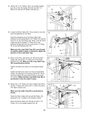
... attached on the indi- 58 cated side of the Press Upright. 8 Route the threaded end of the bracket. Attach a "V"-Pulley (6) and a Long Cable Trap (50) to the bracket on 56 the Press Upright (56) in the direction shown. It may be necessary to the Leg Press Arm (89...) with a 3/8" x 2 1/2" Bolt (7) and a 3/8" Nylon Locknut (21). Locate the Long Cable (58). Route the Long Cable (58) around the "V"-Pulley (6) on the Press Seat Frame (77) with a 3/8" x 4 1/2" 50 Bolt (79) and a 3/8" Nylon Jam Nut (83). It has a...
... attached on the indi- 58 cated side of the Press Upright. 8 Route the threaded end of the bracket. Attach a "V"-Pulley (6) and a Long Cable Trap (50) to the bracket on 56 the Press Upright (56) in the direction shown. It may be necessary to the Leg Press Arm (89...) with a 3/8" x 2 1/2" Bolt (7) and a 3/8" Nylon Locknut (21). Locate the Long Cable (58). Route the Long Cable (58) around the "V"-Pulley (6) on the Press Seat Frame (77) with a 3/8" x 4 1/2" 50 Bolt (79) and a 3/8" Nylon Jam Nut (83). It has a...

English Manual
Page 14
... 57 2 10 58 57 2 10 15 4 71 15 42 83 9 86 32. Locate the Medium Cable (86). Wrap the Medium Cable (86) around a 3 1/2" Pulley (15) in the direction shown. 81 Attach the 3 1/2" Pulley (15) and a Cable Trap (66) to the Long "U"-Bracket (57) with the ball around a 3 1/2" Pulley 32 (15... a 1/4" Nylon Locknut (2) and a 1/4" Flat Washer (10). Do not completely tighten the Nylon Locknut. It should be threaded onto the end of the Cable only a couple of the unit. Attach the Pulley to the other . Move to the Butterfly Upright (42) with a 3/8" x 2" Bolt (12) and a 3/8" Nylon ...
... 57 2 10 58 57 2 10 15 4 71 15 42 83 9 86 32. Locate the Medium Cable (86). Wrap the Medium Cable (86) around a 3 1/2" Pulley (15) in the direction shown. 81 Attach the 3 1/2" Pulley (15) and a Cable Trap (66) to the Long "U"-Bracket (57) with the ball around a 3 1/2" Pulley 32 (15... a 1/4" Nylon Locknut (2) and a 1/4" Flat Washer (10). Do not completely tighten the Nylon Locknut. It should be threaded onto the end of the Cable only a couple of the unit. Attach the Pulley to the other . Move to the Butterfly Upright (42) with a 3/8" x 2" Bolt (12) and a 3/8" Nylon ...
English Manual
Page 15
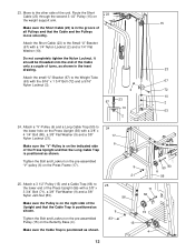
..." x 2 3/4" Bolt (11), a 5/16" Flat Washer (8) and a 5/16" Nylon Locknut (3). Insert the 1/4" x 2 1/2" Carriage Bolt (91) into the center hole in the direction shown. Route the Medium Cable (86) around the Pulley in a Seat Plate (37). Attach the closed loop on the end of the closed loop is positioned as shown. 33 86... 66 12 57 15 21 34. Remove the 3 1/2" Pulley (15) from the Long "U"Bracket (57). Make sure the flat side of the Medium 34 Cable (86) to the Long "U"-Bracket (57) with a 1/4" Flat Washer (10) onto the Carriage Bolt. 36 91 37 77 15 13 18 10 2 Make sure ...
..." x 2 3/4" Bolt (11), a 5/16" Flat Washer (8) and a 5/16" Nylon Locknut (3). Insert the 1/4" x 2 1/2" Carriage Bolt (91) into the center hole in the direction shown. Route the Medium Cable (86) around the Pulley in a Seat Plate (37). Attach the closed loop on the end of the closed loop is positioned as shown. 33 86... 66 12 57 15 21 34. Remove the 3 1/2" Pulley (15) from the Long "U"Bracket (57). Make sure the flat side of the Medium 34 Cable (86) to the Long "U"-Bracket (57) with a 1/4" Flat Washer (10) onto the Carriage Bolt. 36 91 37 77 15 13 18 10 2 Make sure ...
English Manual
Page 19
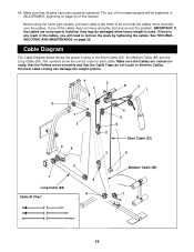
..., find and correct the problem. 46. Cable Diagram The Cable Diagram below shows the proper routing of this manual. Incorrect cable routing can damage the weight system. 4 2 7 8 3 1 2 1 3 5 6 4 7 Long Cable (58) Cable ID Chart 9 8 4 5 6 2 Short Cable (23) 3 9 Medium Cable (86) 1 19 Make sure that the Cable Traps do not touch or bind the Cables. The use of the remaining parts...
..., find and correct the problem. 46. Cable Diagram The Cable Diagram below shows the proper routing of this manual. Incorrect cable routing can damage the weight system. 4 2 7 8 3 1 2 1 3 5 6 4 7 Long Cable (58) Cable ID Chart 9 8 4 5 6 2 Short Cable (23) 3 9 Medium Cable (86) 1 19 Make sure that the Cable Traps do not touch or bind the Cables. The use of the remaining parts...
English Manual
Page 20
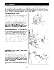
... bar or nylon strap, make sure that the chain is not attached to 106.5 pounds, in the cables or chain as an exercise is any slack in increments of 12.5 pounds. If there is performed, ...stack can be changed from the Seat Frame. Refer to the exercise poster accompanying this manual to the cables and pulleys, the amount of resistance at each weight station. Note: Due to see how the home... gym system should be attached between the Lat Bar and the Medium Cable so the Lat Bar is touching the Weights, and turn the bent end downward. Adjustment The instructions ...
... bar or nylon strap, make sure that the chain is not attached to 106.5 pounds, in the cables or chain as an exercise is any slack in increments of 12.5 pounds. If there is performed, ...stack can be changed from the Seat Frame. Refer to the exercise poster accompanying this manual to the cables and pulleys, the amount of resistance at each weight station. Note: Due to see how the home... gym system should be attached between the Lat Bar and the Medium Cable so the Lat Bar is touching the Weights, and turn the bent end downward. Adjustment The instructions ...

English Manual
Page 21
... be performed. Attach one end of the Chain between the Lat Bar and the Long Cable with two Cable Clips. Attaching the Lat Bar or Nylon Strap to the Low Pulley Station Attach the Lat Bar ...(54) to the Medium Cable (86) with a Cable Clip (53). Always remove the Chain (52) from the Eyebolt (35) before removing the ... REMOVING THE BUTTERFLY SEAT on page 20). Adjust the length of the Chain (52) to the Medium Cable (86) with a Cable Clip. Attach the other end of the foot plate, pull out the Small Lock Pin (90). Move...
... be performed. Attach one end of the Chain between the Lat Bar and the Long Cable with two Cable Clips. Attaching the Lat Bar or Nylon Strap to the Low Pulley Station Attach the Lat Bar ...(54) to the Medium Cable (86) with a Cable Clip (53). Always remove the Chain (52) from the Eyebolt (35) before removing the ... REMOVING THE BUTTERFLY SEAT on page 20). Adjust the length of the Chain (52) to the Medium Cable (86) with a Cable Clip. Attach the other end of the foot plate, pull out the Small Lock Pin (90). Move...

English Manual
Page 22
... the 6.5 lbs. Note: The actual resistance at each weight station may vary due to differences in individual weight plates, as well as friction between the cables, pulleys, and weight guides.
... the 6.5 lbs. Note: The actual resistance at each weight station may vary due to differences in individual weight plates, as well as friction between the cables, pulleys, and weight guides.
English Manual
Page 23
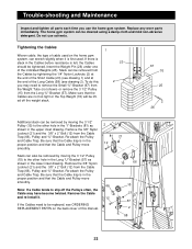
.... The home gym system can be replaced, see drawing 2). Do not use the home gym system. Remove the Cable and re-install it is slack in the proper position and that the Cable and Pulley move 12 smoothly. Slack can be removed by moving the 3 1/2" Pulley (15) to the other ...hole in the "I"-Brackets (81) as shown in the proper position and that the Cable and Pulley move smoothly. 66 Note: If a Cable tends to remove the Small "U"-Bracket (67) from the Weight Tube (not shown) or remove the 3 1/2" Pulley (15) from the...
.... The home gym system can be replaced, see drawing 2). Do not use the home gym system. Remove the Cable and re-install it is slack in the proper position and that the Cable and Pulley move 12 smoothly. Slack can be removed by moving the 3 1/2" Pulley (15) to the other ...hole in the "I"-Brackets (81) as shown in the proper position and that the Cable and Pulley move smoothly. 66 Note: If a Cable tends to remove the Small "U"-Bracket (67) from the Weight Tube (not shown) or remove the 3 1/2" Pulley (15) from the...

English Manual
Page 25
...) 3/8" x 2 1/2" Bolt (7) 5/16" x 2 1/2" Bolt (22) 3/8" x 2 3/4" Bolt (93) 3/8" x 2 3/4" Carriage Bolt (94) 1 1/8" x 2 1/2" Plastic Bushing (74) 1" x 7/8" Plastic Bushing (75) 1/2" x 1 1/4" Spacer (73) 1/2" x 3/4" Spacer (61) 3/8" x 3 1/4" Bolt (85) 3/8" x 3 1/2" Bolt (16) 1" Retainer (69) Cable Clip (53) 3/8" x 3 3/4" Bolt (71) 3/8" x 4 1/4" Bolt (80) 3/8" x 4 1/2" Bolt (79) 3/8" x 7 1/2" Bolt (59)
...) 3/8" x 2 1/2" Bolt (7) 5/16" x 2 1/2" Bolt (22) 3/8" x 2 3/4" Bolt (93) 3/8" x 2 3/4" Carriage Bolt (94) 1 1/8" x 2 1/2" Plastic Bushing (74) 1" x 7/8" Plastic Bushing (75) 1/2" x 1 1/4" Spacer (73) 1/2" x 3/4" Spacer (61) 3/8" x 3 1/4" Bolt (85) 3/8" x 3 1/2" Bolt (16) 1" Retainer (69) Cable Clip (53) 3/8" x 3 3/4" Bolt (71) 3/8" x 4 1/4" Bolt (80) 3/8" x 4 1/2" Bolt (79) 3/8" x 7 1/2" Bolt (59)
English Manual
Page 26
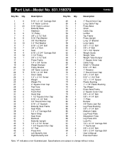
... 18 4 1/4" x 3/4" Screw 19 2 Weight Bumper 20 1 Pulley Bracket 21 19 3/8" Nylon Locknut 22 5 5/16" x 2 1/2" Bolt 23 1 Short Cable 24 1 1/4" x 2 1/4" Screw 25 8 Weight 26 1 Weight Pin 27 7 2" Square Inner Cap 28 2 Pad Tube 29 1 Leg Lever 30 4 ...80 1 3/8" x 4 1/4" Bolt 81 2 "I"-Plate 82 1 Bumper 83 5 3/8" Nylon Jam Nut 84 2 Leg Press Bushing 85 1 3/8" x 3 1/4" Bolt 86 1 Medium Cable 87 1 Leg Press Plate 88 1 Adjustment Tube 89 1 Leg Press Arm 90 1 Lock Pin 91 1 1/4" x 2 1/2" Carriage Bolt 92 1 1" Tap Screw 93 2 3/8" ...
... 18 4 1/4" x 3/4" Screw 19 2 Weight Bumper 20 1 Pulley Bracket 21 19 3/8" Nylon Locknut 22 5 5/16" x 2 1/2" Bolt 23 1 Short Cable 24 1 1/4" x 2 1/4" Screw 25 8 Weight 26 1 Weight Pin 27 7 2" Square Inner Cap 28 2 Pad Tube 29 1 Leg Lever 30 4 ...80 1 3/8" x 4 1/4" Bolt 81 2 "I"-Plate 82 1 Bumper 83 5 3/8" Nylon Jam Nut 84 2 Leg Press Bushing 85 1 3/8" x 3 1/4" Bolt 86 1 Medium Cable 87 1 Leg Press Plate 88 1 Adjustment Tube 89 1 Leg Press Arm 90 1 Lock Pin 91 1 1/4" x 2 1/2" Carriage Bolt 92 1 1" Tap Screw 93 2 3/8" ...


