
English Manual
Page 2
Remove the PART IDENTIFICATION CHART and the PART LIST/EXPLODED DRAWING before beginning assembly. TABLE OF CONTENTS IMPORTANT PRECAUTIONS 3 BEFORE YOU BEGIN 4 ASSEMBLY 5 ADJUSTMENTS 21 WEIGHT RESISTANCE CHART 23 TROUBLE-SHOOTING AND MAINTENANCE 24 CABLE DIAGRAMS 25 ORDERING REPLACEMENT PARTS Back Cover LIMITED WARRANTY Back Cover Note: A PART IDENTIFICATION CHART and a PART LIST/EXPLODED DRAWING are attached at the center of ICON Health & Fitness, Inc. 2 WEIDER is a registered trademark of this manual.
Remove the PART IDENTIFICATION CHART and the PART LIST/EXPLODED DRAWING before beginning assembly. TABLE OF CONTENTS IMPORTANT PRECAUTIONS 3 BEFORE YOU BEGIN 4 ASSEMBLY 5 ADJUSTMENTS 21 WEIGHT RESISTANCE CHART 23 TROUBLE-SHOOTING AND MAINTENANCE 24 CABLE DIAGRAMS 25 ORDERING REPLACEMENT PARTS Back Cover LIMITED WARRANTY Back Cover Note: A PART IDENTIFICATION CHART and a PART LIST/EXPLODED DRAWING are attached at the center of ICON Health & Fitness, Inc. 2 WEIDER is a registered trademark of this manual.
English Manual
Page 3
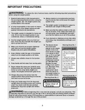
...that the cables remain on the pulleys at all times. 7. IMPORTANT PRECAUTIONS WARNING: To reduce the risk of all precautions. 3. Use the weight system only on page 4. Keep hands and feet away from the leg press upright when the military press arm is the responsibility of the ... 13. Warning Decal No. 2 Warning Decal No. 1 Warning Decal No. 3 11. ICON assumes no responsibility for foot protection. 8. Do not use the weight system. until 6 p.m. Place the decal on a foot plate when performing an exercise that could become pinched between the leg press upright and military press arm...
...that the cables remain on the pulleys at all times. 7. IMPORTANT PRECAUTIONS WARNING: To reduce the risk of all precautions. 3. Use the weight system only on page 4. Keep hands and feet away from the leg press upright when the military press arm is the responsibility of the ... 13. Warning Decal No. 2 Warning Decal No. 1 Warning Decal No. 3 11. ICON assumes no responsibility for foot protection. 8. Do not use the weight system. until 6 p.m. Place the decal on a foot plate when performing an exercise that could become pinched between the leg press upright and military press arm...
English Manual
Page 4
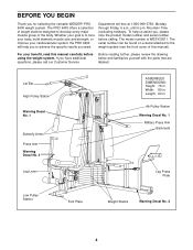
... is to achieve the specific results you for selecting the versatile WEIDER® PRO 9400 weight system. Ab Pulley Station Warning Decal No. 1 Military Press Arm Backrests Leg Lever Leg Press Plate Low Pulley Station Foot Plate Weight Stacks Warning Decal No. 2 4 To help you to tone...body, build dramatic muscle size and strength, or improve your benefit, read this manual). Length: 64 in . The PRO 9400 offers a selection of weight stations designed to the weight system (see the front cover of the body. until 6 p.m. Mountain Time (excluding holidays). The serial number can...
... is to achieve the specific results you for selecting the versatile WEIDER® PRO 9400 weight system. Ab Pulley Station Warning Decal No. 1 Military Press Arm Backrests Leg Lever Leg Press Plate Low Pulley Station Foot Plate Weight Stacks Warning Decal No. 2 4 To help you to tone...body, build dramatic muscle size and strength, or improve your benefit, read this manual). Length: 64 in . The PRO 9400 offers a selection of weight stations designed to the weight system (see the front cover of the body. until 6 p.m. Mountain Time (excluding holidays). The serial number can...
English Manual
Page 5
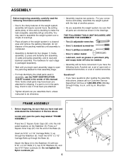
... following tools: A socket set, a set of open-end or closed-end wrenches, or a set of ratchet wrenches. For your convenience and safety, assemble the weight system with two 5/16" x 2 3/4" Bolts (11), two 5/16" Washers (8), and two 5/16" Nylon Locknuts (3). until you assemble them, unless instructed ...the drawings. If a part is not in the parts bag, check to see if it has been pre-attached. • Tighten all parts of the weight system in the center of the packing materials until assembly is completed. • Assembly is packaged separately. • Wait until 6 p.m. FRAME ASSEMBLY 1...
... following tools: A socket set, a set of open-end or closed-end wrenches, or a set of ratchet wrenches. For your convenience and safety, assemble the weight system with two 5/16" x 2 3/4" Bolts (11), two 5/16" Washers (8), and two 5/16" Nylon Locknuts (3). until you assemble them, unless instructed ...the drawings. If a part is not in the parts bag, check to see if it has been pre-attached. • Tighten all parts of the weight system in the center of the packing materials until assembly is completed. • Assembly is packaged separately. • Wait until 6 p.m. FRAME ASSEMBLY 1...
English Manual
Page 7
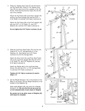
... 8 is complete. 6 25 19 Bracket Pin Grooves 25 5 Bracket 4 7 Pin Grooves 19 Press a 2" Square Inner Cap (27) into the top of Weight Bumpers (19). Press a 1 3/4" Square Inner Cap (44) into each set of the crossbar. 27 Attach the Top Frame (55) to the Leg Press ...2 1/2" Carriage Bolts (1) and two 5/16" Nylon Locknuts (3). Attach the Top Frame (55) to tip either stack of Weights. Tighten all 5/16" Nylon Locknuts (3) used in the Stabilizer (5). 4. Set two Weight Bumpers (19) on the bracket on the Stabilizer (5). Attach the other end of 4 the Top Frame (55). Be sure...
... 8 is complete. 6 25 19 Bracket Pin Grooves 25 5 Bracket 4 7 Pin Grooves 19 Press a 2" Square Inner Cap (27) into the top of Weight Bumpers (19). Press a 1 3/4" Square Inner Cap (44) into each set of the crossbar. 27 Attach the Top Frame (55) to the Leg Press ...2 1/2" Carriage Bolts (1) and two 5/16" Nylon Locknuts (3). Attach the Top Frame (55) to tip either stack of Weights. Tighten all 5/16" Nylon Locknuts (3) used in the Stabilizer (5). 4. Set two Weight Bumpers (19) on the bracket on the Stabilizer (5). Attach the other end of 4 the Top Frame (55). Be sure...
English Manual
Page 8
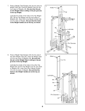
... into the rear stack of the other Top Weight (65). Insert the Weight Tube 8 Holes into the end of Weights (25). Lubricate the inside of Weights. Be sure that the pin on the Weight Tube is sitting in the pin grooves in the Top Weight (65). Lubricate 65 Pin 63 64 Pin...the stack of the holes in the top Weight. Lubricate the inside of Weights. Insert the Weight Tube into the end of Weights (25). Set the Top Weight onto the front stack of Weights (25). Set the Top Weight onto the rear stack of a Weight Tube (63). Press a Weight Tube Bumper (64) into the front stack...
... into the rear stack of the other Top Weight (65). Insert the Weight Tube 8 Holes into the end of Weights (25). Lubricate the inside of Weights. Be sure that the pin on the Weight Tube is sitting in the pin grooves in the Top Weight (65). Lubricate 65 Pin 63 64 Pin...the stack of the holes in the top Weight. Lubricate the inside of Weights. Insert the Weight Tube into the end of Weights (25). Set the Top Weight onto the front stack of Weights (25). Set the Top Weight onto the rear stack of a Weight Tube (63). Press a Weight Tube Bumper (64) into the front stack...
English Manual
Page 9
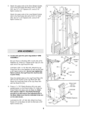
Do not over tighten the Nylon Locknut; Note: This will be able to the Leg Press Arm with one set of the Short Weight Guides (73) to the Stabilizer (5) with a 5/16" x 6" Bolt (60), two 1/2" x 3/4" Spacers (61), and a 5/16" Nylon Locknut (3). Make sure that the indicated holes ... is a Bushing (98) in the Base. Align the welded tubes on the Press Frame (17). Press a 1" x 7/8" Plastic Bushing (90) onto each side of the Long Weight Guides (62) to the Base (4) with a 5/16" x 6" Bolt (60), two 1/2" x 3/4" Spacers (61), and a 5/16" Nylon Locknut (3). 9 61 60 73 3 61 60 3 55 ...
Do not over tighten the Nylon Locknut; Note: This will be able to the Leg Press Arm with one set of the Short Weight Guides (73) to the Stabilizer (5) with a 5/16" x 6" Bolt (60), two 1/2" x 3/4" Spacers (61), and a 5/16" Nylon Locknut (3). Make sure that the indicated holes ... is a Bushing (98) in the Base. Align the welded tubes on the Press Frame (17). Press a 1" x 7/8" Plastic Bushing (90) onto each side of the Long Weight Guides (62) to the Base (4) with a 5/16" x 6" Bolt (60), two 1/2" x 3/4" Spacers (61), and a 5/16" Nylon Locknut (3). 9 61 60 73 3 61 60 3 55 ...
English Manual
Page 13
... Pulley move smoothly. 58 15 12 57 Bracket 58 15 58 12 15 21 24. Attach a 3 1/2" Pulley (15) and a Cable Trap (66) to the indicated Weight Tube (63) with a 3/8" x 2" Bolt (12) and a 3/8" Nylon Locknut (21). Note: This may come pre-assembled. Route the High Cable (58) through the Long "U"Bracket (57...
... Pulley move smoothly. 58 15 12 57 Bracket 58 15 58 12 15 21 24. Attach a 3 1/2" Pulley (15) and a Cable Trap (66) to the indicated Weight Tube (63) with a 3/8" x 2" Bolt (12) and a 3/8" Nylon Locknut (21). Note: This may come pre-assembled. Route the High Cable (58) through the Long "U"Bracket (57...
English Manual
Page 15
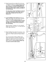
You may need to lift the Top Weight (not shown) on the Stabilizer (5) with a 5/16" x 1 3/4" Bolt (24) and a 5/16" Nylon Locknut (3). 31. Attach the Small "U"-Bracket (71) to the Long "U"Bracket (57). 30. ... and a Cable Trap (66) to the bracket on the High Cable (58) to get enough slack to attach the Low Cable (23) to the indicated Weight Tube (63) with a 3/8" x 2" Bolt (12) and a 3/8" Nylon Locknut (21). Attach the end of threads are showing above the Nylon Locknut, as shown in the inset...
You may need to lift the Top Weight (not shown) on the Stabilizer (5) with a 5/16" x 1 3/4" Bolt (24) and a 5/16" Nylon Locknut (3). 31. Attach the Small "U"-Bracket (71) to the Long "U"Bracket (57). 30. ... and a Cable Trap (66) to the bracket on the High Cable (58) to get enough slack to attach the Low Cable (23) to the indicated Weight Tube (63) with a 3/8" x 2" Bolt (12) and a 3/8" Nylon Locknut (21). Attach the end of threads are showing above the Nylon Locknut, as shown in the inset...
English Manual
Page 16
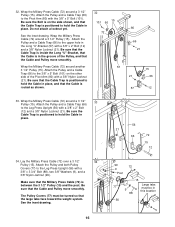
... Cable (72) around a 3 1/2" Pulley (15). Be sure the Bolt is on the other side of the Pulley, and that the large tabs face toward the weight system. Wrap the Military Press Cable (72) around another 3 1/2" Pulley (15). Wrap the Military Press Cable (72) around a 3 1/2" 33 Pulley (15). Be sure that the...
... Cable (72) around a 3 1/2" Pulley (15). Be sure the Bolt is on the other side of the Pulley, and that the large tabs face toward the weight system. Wrap the Military Press Cable (72) around another 3 1/2" Pulley (15). Wrap the Military Press Cable (72) around a 3 1/2" 33 Pulley (15). Be sure that the...
English Manual
Page 20
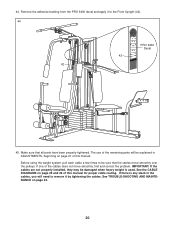
IMPORTANT: If the cables are not properly installed, they may be damaged when heavy weight is any slack in ADJUSTMENTS, beginning on page 21 of the remaining parts will need to remove it to be explained in the cables, you ... use of this manual for proper cable routing. Remove the adhesive backing from the PRO 9400 decal and apply it by tightening the cables. Before using the weight system, pull each cable a few times to the Front Upright (42). 44 PRO 9400 Decal 42 42 45. See the CABLE DIAGRAMS on page 24. 20 Make...
IMPORTANT: If the cables are not properly installed, they may be damaged when heavy weight is any slack in ADJUSTMENTS, beginning on page 21 of the remaining parts will need to remove it to be explained in the cables, you ... use of this manual for proper cable routing. Remove the adhesive backing from the PRO 9400 decal and apply it by tightening the cables. Before using the weight system, pull each cable a few times to the Front Upright (42). 44 PRO 9400 Decal 42 42 45. See the CABLE DIAGRAMS on page 24. 20 Make...
English Manual
Page 21
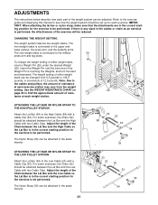
...The Nylon Strap (39) can be changed from the weight setting. CHANGING THE WEIGHT SETTING The weight system features two weight stacks. Insert the Weight Pin until the bent end of 12.5 pounds. The weight setting of either weight stack, insert a Weight Pin (26) under the desired Weight (25). Adjust the length of the Chain between the...the Chain (52) should be attached between the Lat Bar and the Low Cable so the Lat Bar is performed, the effectiveness of either weight stack can be reduced. The Nylon Strap (39) can be performed. If there is any slack in the cables or chain as an ...
...The Nylon Strap (39) can be changed from the weight setting. CHANGING THE WEIGHT SETTING The weight system features two weight stacks. Insert the Weight Pin until the bent end of 12.5 pounds. The weight setting of either weight stack, insert a Weight Pin (26) under the desired Weight (25). Adjust the length of the Chain between the...the Chain (52) should be attached between the Lat Bar and the Low Cable so the Lat Bar is performed, the effectiveness of either weight stack can be reduced. The Nylon Strap (39) can be performed. If there is any slack in the cables or chain as an ...
English Manual
Page 23
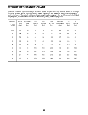
The other numbers refer to the 6.5 lb. WEIGHT PLATES PRESS BUTTERFLY ARM ARM (lbs.) (lbs.) LEG LEVER (lbs.) HIGH PULLEY (lbs.) LOW PULLEY (lbs.) MILITARY PRESS ARM (lbs.) LEG PRESS (lbs.) AB STATION (.... "Top" refers to the 12.5 lb. top weight. The actual resistance at each weight station may vary due to differences in individual weight plates, as well as friction between the cables, pulleys, and weight guides. WEIGHT RESISTANCE CHART This chart shows the approximate weight resistance at each weight station. The butterfly arm resistance listed is the resistance...
The other numbers refer to the 6.5 lb. WEIGHT PLATES PRESS BUTTERFLY ARM ARM (lbs.) (lbs.) LEG LEVER (lbs.) HIGH PULLEY (lbs.) LOW PULLEY (lbs.) MILITARY PRESS ARM (lbs.) LEG PRESS (lbs.) AB STATION (.... "Top" refers to the 12.5 lb. top weight. The actual resistance at each weight station may vary due to differences in individual weight plates, as well as friction between the cables, pulleys, and weight guides. WEIGHT RESISTANCE CHART This chart shows the approximate weight resistance at each weight station. The butterfly arm resistance listed is the resistance...
English Manual
Page 24
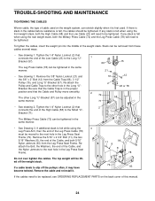
... from these cables several ways: • See drawing 1. Tighten the 1/4" Nylon Locknut (2) that connects the end of the Low Cable (23) to slip off the weight stack. The Military Press Cable (72) can be tightened. Do not over tighten the cables. If any slack is felt while using the 3 Leg Press..., the Washers, the end of the Cable, and the Nylon Jamnuts to be lifted off the pulleys often, it is felt when using the front weight stack, both 5/16" Nylon Jamnuts (93) from the Leg Press Seat Frame. If a cable tends to the Long "U"Bracket (57). TROUBLE-SHOOTING AND MAINTENANCE ...
... from these cables several ways: • See drawing 1. Tighten the 1/4" Nylon Locknut (2) that connects the end of the Low Cable (23) to slip off the weight stack. The Military Press Cable (72) can be tightened. Do not over tighten the cables. If any slack is felt while using the 3 Leg Press..., the Washers, the end of the Cable, and the Nylon Jamnuts to be lifted off the pulleys often, it is felt when using the front weight stack, both 5/16" Nylon Jamnuts (93) from the Leg Press Seat Frame. If a cable tends to the Long "U"Bracket (57). TROUBLE-SHOOTING AND MAINTENANCE ...
English Manual
Page 25
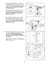
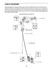
... assembled correctly. High Cable (58) and Low Cable (23) 7 5 23 4 1-High Pulley TOP VIEW 6 High Cable (58) 5-Long "U"-Bracket Low Cable (23) Front Weight Stack-8 4 3 2 1-Low Pulley 25 The insets show the proper routing of the cable traps. CABLE DIAGRAMS The cable diagrams on these pages show the proper...(72), and the Leg Press Cable (78). Be sure that the four cables and the cable traps have not been correctly routed, the weight system will not come off the pulleys. Use the diagrams to be positioned so that the cables will not function properly and damage may occur...
... assembled correctly. High Cable (58) and Low Cable (23) 7 5 23 4 1-High Pulley TOP VIEW 6 High Cable (58) 5-Long "U"-Bracket Low Cable (23) Front Weight Stack-8 4 3 2 1-Low Pulley 25 The insets show the proper routing of the cable traps. CABLE DIAGRAMS The cable diagrams on these pages show the proper...(72), and the Leg Press Cable (78). Be sure that the four cables and the cable traps have not been correctly routed, the weight system will not come off the pulleys. Use the diagrams to be positioned so that the cables will not function properly and damage may occur...
English Manual
Page 26
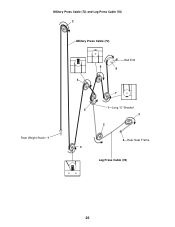
Military Press Cable (72) and Leg Press Cable (78) 2 Military Press Cable (72) Rear Weight Stack-1 4 5 Ball End 6 8 7 1-Long "U"-Bracket 3 2 4-Rear Seat Frame 3 Leg Press Cable (78) 26
Military Press Cable (72) and Leg Press Cable (78) 2 Military Press Cable (72) Rear Weight Stack-1 4 5 Ball End 6 8 7 1-Long "U"-Bracket 3 2 4-Rear Seat Frame 3 Leg Press Cable (78) 26
English Manual
Page 31
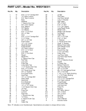
... Long "U"-Bracket 58 1 High Cable 59 1 3/8" x 8" Bolt 60 2 5/16" x 6" Bolt 61 4 1/2" x 3/4" Spacer 62 2 Long Weight Guide 63 2 Weight Tube 64 2 Weight Tube Bumper 65 2 Top Weight 66 10 Cable Trap 67 2 3/8" x 3 1/4" Bolt 68 1 5/16" x 5" Bolt 69 4 1" Retainer 70 2 1" Round Cover Cap 71... 2 Small "U"-Bracket 72 1 Military Press Cable 73 2 Short Weight Guide 74 1 Rear Upright 75 2 Round Inner Cap 76 1 3 1/2" Low Pulley 77 2 Pulley Cover 78 1 Leg Press Cable 79 1 Leg...
... Long "U"-Bracket 58 1 High Cable 59 1 3/8" x 8" Bolt 60 2 5/16" x 6" Bolt 61 4 1/2" x 3/4" Spacer 62 2 Long Weight Guide 63 2 Weight Tube 64 2 Weight Tube Bumper 65 2 Top Weight 66 10 Cable Trap 67 2 3/8" x 3 1/4" Bolt 68 1 5/16" x 5" Bolt 69 4 1" Retainer 70 2 1" Round Cover Cap 71... 2 Small "U"-Bracket 72 1 Military Press Cable 73 2 Short Weight Guide 74 1 Rear Upright 75 2 Round Inner Cap 76 1 3 1/2" Low Pulley 77 2 Pulley Cover 78 1 Leg Press Cable 79 1 Leg...
English Manual
Page 33
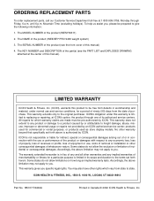
... & FITNESS, INC., 1500 S. 1000 W., LOGAN, UT 84321-9813 Part No. 185317 R0402A Printed in its authorized service centers. The MODEL NUMBER of the product (WEIDER® PRO 9400 weight system) 3. ICON's obligation under normal use and service conditions, for indirect, special or consequential damages arising out of or in lieu of any and all...
... & FITNESS, INC., 1500 S. 1000 W., LOGAN, UT 84321-9813 Part No. 185317 R0402A Printed in its authorized service centers. The MODEL NUMBER of the product (WEIDER® PRO 9400 weight system) 3. ICON's obligation under normal use and service conditions, for indirect, special or consequential damages arising out of or in lieu of any and all...


