
English Manual
Page 6
... tools. Seat Assembly—-During the final stage you will assemble the arms and the leg lever. Arm Assembly—-During this stage you will attach the cables and pulleys that connect the arms to walk around the weight system. •• Place all parts in the location where it will...
... tools. Seat Assembly—-During the final stage you will assemble the arms and the leg lever. Arm Assembly—-During this stage you will attach the cables and pulleys that connect the arms to walk around the weight system. •• Place all parts in the location where it will...

English Manual
Page 7
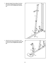
the Foot Plate must pivot easily. 56 1 72 38 2. Do not overtighten the Locknut; Do not tighten the Locknuts yet. 21 2 71 1 71 57 56 57 7 Attach the Foot Plate (38) to the Stabilizer (2) with an M10 x 130mm Bolt (72) and an M10 Locknut (56). Frame Assembly 1 1. Attach the Weight Guides (21) and the Base 2 (1) to the Base (1) with two M10 x 67mm Bolts (71), two M10 Washers (57), and two M10 Locknuts (56).
the Foot Plate must pivot easily. 56 1 72 38 2. Do not overtighten the Locknut; Do not tighten the Locknuts yet. 21 2 71 1 71 57 56 57 7 Attach the Foot Plate (38) to the Stabilizer (2) with an M10 x 130mm Bolt (72) and an M10 Locknut (56). Frame Assembly 1 1. Attach the Weight Guides (21) and the Base 2 (1) to the Base (1) with two M10 x 67mm Bolts (71), two M10 Washers (57), and two M10 Locknuts (56).
English Manual
Page 8
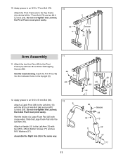
3. Attach the Upright (3) to the Base (1) with two 3 M8 x 63mm Carriage Bolts (87) and two M8 Locknuts (58). Do not tighten the Locknuts yet. 58 58 1 87 7 58 58 1 87 8 Do not tighten the Locknuts yet. 3 4. Attach the Front Leg (7) to the Base (1) with two M8 x 63mm Carriage Bolts (87) and two M8 4 Locknuts (58).
3. Attach the Upright (3) to the Base (1) with two 3 M8 x 63mm Carriage Bolts (87) and two M8 Locknuts (58). Do not tighten the Locknuts yet. 58 58 1 87 7 58 58 1 87 8 Do not tighten the Locknuts yet. 3 4. Attach the Front Leg (7) to the Base (1) with two M8 x 63mm Carriage Bolts (87) and two M8 4 Locknuts (58).

English Manual
Page 9
... (22) so that the pin on the bottom as shown. Make sure that the pin holes are on the Weight Selector is oriented as shown. Attach the Seat Tube (6) to the Upright (3) with 5 two M8 x 65mm Bolts (68), two M8 Washers (59), and two M8 Locknuts (58). Apply some of the... included grease inside the indicated holes in the same way. 6 7 59 58 3 68 68 68 68 58 59 6. Attach the Seat Tube (6) to the Front Leg (7) in the remaining Weight (22). 5.
... (22) so that the pin on the bottom as shown. Make sure that the pin holes are on the Weight Selector is oriented as shown. Attach the Seat Tube (6) to the Upright (3) with 5 two M8 x 65mm Bolts (68), two M8 Washers (59), and two M8 Locknuts (58). Apply some of the... included grease inside the indicated holes in the same way. 6 7 59 58 3 68 68 68 68 58 59 6. Attach the Seat Tube (6) to the Front Leg (7) in the remaining Weight (22). 5.

English Manual
Page 10
... that the barrel of the bracket on the Front Leg. 76 Grease 7 8 76 10 Apply grease to an M10 x 64mm Bolt Set (76). 9 Attach the Leg Lever (8) to 7. 7. Attach the Top Frame (4) to the Weight Guides (21) with the M10 x 64mm Bolt Set (76). Make sure that the end of the Leg... the Bolt Set is pointing upward. 7 60 33 69 9. Tighten the M10 Locknuts (56) and the M8 Locknuts (58). 74 71 57 4 21 56 56 3 8. Attach the Top Frame (4) to the Upright (3) with an M4 x 20mm Self-tapping Screw (69) and an M4 Washer (33...
... that the barrel of the bracket on the Front Leg. 76 Grease 7 8 76 10 Apply grease to an M10 x 64mm Bolt Set (76). 9 Attach the Leg Lever (8) to 7. 7. Attach the Top Frame (4) to the Weight Guides (21) with the M10 x 64mm Bolt Set (76). Make sure that the end of the Leg... the Bolt Set is pointing upward. 7 60 33 69 9. Tighten the M10 Locknuts (56) and the M8 Locknuts (58). 74 71 57 4 21 56 56 3 8. Attach the Top Frame (4) to the Upright (3) with an M4 x 20mm Self-tapping Screw (69) and an M4 Washer (33...
English Manual
Page 11
...) 12 9 with the M10 x 51mm Bolt (66) and an M10 Locknut (56). Do not overtighten the Locknut; Attach a Handle (11) to the Left Arm (10) with soapy water. See the inset drawing. the Cable Pivot must pivot... of a Large Foam Pad (42) with two M10 x 25mm Button Screws (77) and two M10 Washers (57). Attach the two Arm Pins (40) to the Top Frame (4) with two M4 x 20mm Self-tapping Screws (69). Insert ... 66 56 Grease 39 10 42 11 57 77 Apply grease to an M10 x 77mm Bolt (79). 10 Attach the Pivot Frame (5) to the Pivot Frame (5) with the M10 x 77mm Bolt (79) and an M10 ...
...) 12 9 with the M10 x 51mm Bolt (66) and an M10 Locknut (56). Do not overtighten the Locknut; Attach a Handle (11) to the Left Arm (10) with soapy water. See the inset drawing. the Cable Pivot must pivot... of a Large Foam Pad (42) with two M10 x 25mm Button Screws (77) and two M10 Washers (57). Attach the two Arm Pins (40) to the Top Frame (4) with two M4 x 20mm Self-tapping Screws (69). Insert ... 66 56 Grease 39 10 42 11 57 77 Apply grease to an M10 x 77mm Bolt (79). 10 Attach the Pivot Frame (5) to the Pivot Frame (5) with the M10 x 77mm Bolt (79) and an M10 ...

English Manual
Page 12
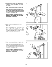
... same way. 9 5 67 20 Grease 44 57 56 Grease 10 44 Cable Assembly 14 14. Attach the Right Arm (9) to two Arm Bushings (44). See the CABLE DIAGRAM on page 24 to an M8 x 22mm ...Shoulder Bolt (65). Attach the Left Arm (10) to the left Cable Pivot (39) with the M10 x 86mm Carriage Bolt (67),...), an M10 Washer (57), and an M10 Locknut (56). Apply grease to identify the cables as you assemble them. Attach the Arm Cable (54) to the Pivot Frame (5) with the M8 x 22mm Shoulder Bolt (65) and an M8 ...
... same way. 9 5 67 20 Grease 44 57 56 Grease 10 44 Cable Assembly 14 14. Attach the Right Arm (9) to two Arm Bushings (44). See the CABLE DIAGRAM on page 24 to an M8 x 22mm ...Shoulder Bolt (65). Attach the Left Arm (10) to the left Cable Pivot (39) with the M10 x 86mm Carriage Bolt (67),...), an M10 Washer (57), and an M10 Locknut (56). Apply grease to identify the cables as you assemble them. Attach the Arm Cable (54) to the Pivot Frame (5) with the M8 x 22mm Shoulder Bolt (65) and an M8 ...
English Manual
Page 13
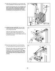
Attach the V-pulley (46), a Large Cable Trap (50), two Full Guards (41), and an M10 Washer (57) to the Upright ...Thick 15 Pulleys (not shown), and the two Thin Pulleys (not shown). Route the Arm Cable (54) around a Thick Pulley (48). 16 Attach the Thick Pulley (48) and two Half Guards (43) to hold the Arm Cable (54) in the groove of the V-pulley (46).... 3 41 57 46 50 41 75 56 54 16. Route the Arm Cable (54) over a V-pulley (46). 17 Attach the V-pulley (46), a Large Cable Trap (50), two Full Guards (41), and an M10 Washer (57) to the Upright (3) with an ...
Attach the V-pulley (46), a Large Cable Trap (50), two Full Guards (41), and an M10 Washer (57) to the Upright ...Thick 15 Pulleys (not shown), and the two Thin Pulleys (not shown). Route the Arm Cable (54) around a Thick Pulley (48). 16 Attach the Thick Pulley (48) and two Half Guards (43) to hold the Arm Cable (54) in the groove of the V-pulley (46).... 3 41 57 46 50 41 75 56 54 16. Route the Arm Cable (54) over a V-pulley (46). 17 Attach the V-pulley (46), a Large Cable Trap (50), two Full Guards (41), and an M10 Washer (57) to the Upright (3) with an ...

English Manual
Page 14
... Leg (7), above the Low Cable (53), with the M8 x 22mm Shoulder Bolt (65) and an M8 Locknut (58). 18 Grease 65 54 39 58 19. Attach a Thick Pulley (48) inside the Leg Lever (8), above the Low Cable (53), with an M10 x 67mm Bolt (71), two M10 Washers (57), two 13mm Spacers...
... Leg (7), above the Low Cable (53), with the M8 x 22mm Shoulder Bolt (65) and an M8 Locknut (58). 18 Grease 65 54 39 58 19. Attach a Thick Pulley (48) inside the Leg Lever (8), above the Low Cable (53), with an M10 x 67mm Bolt (71), two M10 Washers (57), two 13mm Spacers...

English Manual
Page 15
Attach the Thick Pulley (48) inside the Upright (3) with an M10 x 46mm Bolt (81) and an M10 Locknut (56). Make...outside of the bracket as shown. 43 56 53 63 43 48 81 23. Route the Low Cable (53) under a Thick Pulley (48). Attach the Thick Pulley (48) and two Half Guards (43) to the Base (1) with an M10 x 46mm Bolt (81) and an M10 Locknut... (56). Route the Low Cable (53) over a Thick 22 Pulley (48). 21. Attach the Thick Pulley (48) and two Half Guards (43) to the Double U-bracket (63) with an M10 x 46mm Bolt (81) and an M10 ...
Attach the Thick Pulley (48) inside the Upright (3) with an M10 x 46mm Bolt (81) and an M10 Locknut (56). Make...outside of the bracket as shown. 43 56 53 63 43 48 81 23. Route the Low Cable (53) under a Thick Pulley (48). Attach the Thick Pulley (48) and two Half Guards (43) to the Base (1) with an M10 x 46mm Bolt (81) and an M10 Locknut... (56). Route the Low Cable (53) over a Thick 22 Pulley (48). 21. Attach the Thick Pulley (48) and two Half Guards (43) to the Double U-bracket (63) with an M10 x 46mm Bolt (81) and an M10 ...
English Manual
Page 16
... the Top Frame (4) and 25 over a Thin Pulley (47) and downward through the Top Frame (4). 26 Attach the Thin Pulley (47) inside the Top Frame (4) with an M8 Washer (59) and an M8 Locknut... (58). Identify the High Cable (55). Route the High Cable (55) over a Thick Pulley (48). 48 Attach the Thick Pulley (48) inside the Top Frame (4) with an M10 x 67mm Bolt (71), an M10 Washer (57...), and an 11mm Spacer (86). 24. See the inset drawing. Attach the Low Cable (53) to the U-bracket (45) 24 with an M10 x 67mm Bolt (71), two M10 Washers...
... the Top Frame (4) and 25 over a Thin Pulley (47) and downward through the Top Frame (4). 26 Attach the Thin Pulley (47) inside the Top Frame (4) with an M8 Washer (59) and an M8 Locknut... (58). Identify the High Cable (55). Route the High Cable (55) over a Thick Pulley (48). 48 Attach the Thick Pulley (48) inside the Top Frame (4) with an M10 x 67mm Bolt (71), an M10 Washer (57...), and an 11mm Spacer (86). 24. See the inset drawing. Attach the Low Cable (53) to the U-bracket (45) 24 with an M10 x 67mm Bolt (71), two M10 Washers...

English Manual
Page 17
...a Thick Pulley 29 (48) and downward through the Top Frame (4) and over a Thin Pulley (47). 28 Attach the Thin Pulley (47) inside the Top Frame (4) with an M10 x 51mm Bolt (66) and an M10 Locknut (56...). Attach the Thick Pulley (48), a Small Cable Trap (51), and two Half Guards (43) to hold the High ... (57), and an M10 Locknut (56). 56 43 45 55 48 51 43 66 55 47 56 4 57 86 71 29. Attach the Thick Pulley (48) inside the Top Frame (4) with the M10 x 67mm Bolt (71) used in the U-bracket (45) with...
...a Thick Pulley 29 (48) and downward through the Top Frame (4) and over a Thin Pulley (47). 28 Attach the Thin Pulley (47) inside the Top Frame (4) with an M10 x 51mm Bolt (66) and an M10 Locknut (56...). Attach the Thick Pulley (48), a Small Cable Trap (51), and two Half Guards (43) to hold the High ... (57), and an M10 Locknut (56). 56 43 45 55 48 51 43 66 55 47 56 4 57 86 71 29. Attach the Thick Pulley (48) inside the Top Frame (4) with the M10 x 67mm Bolt (71) used in the U-bracket (45) with...

English Manual
Page 18
... Seat Frame. Tighten the High Cable (55) into the Upright and one of the holes in the Backrest Frame. 91 61 62 82 64 3 32. Attach the Seat (15) to the Backrest Frame (61) with two M6 x 16mm Screws (62), an M6 x 38mm 32 Screw (95), and an M6 Washer (82... (91) into the Seat Tube and one of the Weight Selector (24). Thread an M12 Nut (84) all the slack is removed from the cables. Attach the Backrest (16) to the Seat Frame (73) with two M6 x 16mm Screws (62), an M6 x 32mm Screw (64), and an M6 Washer (82). 16...
... Seat Frame. Tighten the High Cable (55) into the Upright and one of the holes in the Backrest Frame. 91 61 62 82 64 3 32. Attach the Seat (15) to the Backrest Frame (61) with two M6 x 16mm Screws (62), an M6 x 38mm 32 Screw (95), and an M6 Washer (82... (91) into the Seat Tube and one of the Weight Selector (24). Thread an M12 Nut (84) all the slack is removed from the cables. Attach the Backrest (16) to the Seat Frame (73) with two M6 x 16mm Screws (62), an M6 x 32mm Screw (64), and an M6 Washer (82). 16...

English Manual
Page 19
Attach a Shroud Support (19) and the top of the 34 Left Shroud (17) to the top of the Leg Lever (8). Do not tighten the Screws yet. 4 ...) and the Shroud Support (19) with two M4.2 x 16mm Self-tapping Screws (49) and two M4 Washers (33). Do not tighten the Screws yet. Then, attach a Shroud Clamp (90) to the left side of the Pad Tube (29). Slide a Small Foam Pad (28) onto each side of the Top Frame (4) with...
Attach a Shroud Support (19) and the top of the 34 Left Shroud (17) to the top of the Leg Lever (8). Do not tighten the Screws yet. 4 ...) and the Shroud Support (19) with two M4.2 x 16mm Self-tapping Screws (49) and two M4 Washers (33). Do not tighten the Screws yet. Then, attach a Shroud Clamp (90) to the left side of the Pad Tube (29). Slide a Small Foam Pad (28) onto each side of the Top Frame (4) with...

English Manual
Page 20
See steps 34 and 35. Attach the Curl Pad (14) to the Curl Post (13) 36 with four M4.2 x 16mm Self-tapping Screws (49)... CABLE DIAGRAM on page 25. 20 Before using the weight system, pull each cable a few times to attach the Right Shroud (not shown). Do not tighten the Screws yet. See MAINTENANCE on page 24 for proper cable routing. 35.... Attach a Shroud Support (19) and the bottom of the cables does not move smoothly around the pulleys. If there is used...
See steps 34 and 35. Attach the Curl Pad (14) to the Curl Post (13) 36 with four M4.2 x 16mm Self-tapping Screws (49)... CABLE DIAGRAM on page 25. 20 Before using the weight system, pull each cable a few times to attach the Right Shroud (not shown). Do not tighten the Screws yet. See MAINTENANCE on page 24 for proper cable routing. 35.... Attach a Shroud Support (19) and the bottom of the cables does not move smoothly around the pulleys. If there is used...

English Manual
Page 21
...see the correct form for several exercises. Replace any worn parts immediately. For some exercises, attach the Chain (83) between the Lat Bar and the High Cable so that the Lat ...(55) with a Cable Clip (37). Adjust the length of resistance at each weight station. 22 26 ATTACHING THE ACCESSORIES Attach the Lat Bar (35) to the High Cable (55) at each time the weight system is in the...to be performed. 83 The Lat Bar (35) or the Handle Strap (not shown) can be attached at either pulley station in the correct starting position for important information about how to the cables and pulleys...
...see the correct form for several exercises. Replace any worn parts immediately. For some exercises, attach the Chain (83) between the Lat Bar and the High Cable so that the Lat ...(55) with a Cable Clip (37). Adjust the length of resistance at each weight station. 22 26 ATTACHING THE ACCESSORIES Attach the Lat Bar (35) to the High Cable (55) at each time the weight system is in the...to be performed. 83 The Lat Bar (35) or the Handle Strap (not shown) can be attached at either pulley station in the correct starting position for important information about how to the cables and pulleys...

