
User Manual
Page 2
... actual size. 2 TABLE OF CONTENTS WARNING DECAL PLACEMENT 2 IMPORTANT PRECAUTIONS 3 BEFORE YOU BEGIN 4 PART IDENTIFICATION CHART 5 ASSEMBLY 8 ADJUSTMENT 25 WEIGHT RESISTANCE CHART 27 CABLE DIAGRAM 28 MAINTENANCE 29 EXERCISE GUIDELINES 30 PART LIST 33 EXPLODED DRAWING 34 ORDERING REPLACEMENT PARTS Back Cover 90 DAY FULL WARRANTY Back Cover WARNING DECAL PLACEMENT The decal shown...
... actual size. 2 TABLE OF CONTENTS WARNING DECAL PLACEMENT 2 IMPORTANT PRECAUTIONS 3 BEFORE YOU BEGIN 4 PART IDENTIFICATION CHART 5 ASSEMBLY 8 ADJUSTMENT 25 WEIGHT RESISTANCE CHART 27 CABLE DIAGRAM 28 MAINTENANCE 29 EXERCISE GUIDELINES 30 PART LIST 33 EXPLODED DRAWING 34 ORDERING REPLACEMENT PARTS Back Cover 90 DAY FULL WARRANTY Back Cover WARNING DECAL PLACEMENT The decal shown...
User Manual
Page 3
...Do not use of weight to mount, dismount, and use the weight system. 6. If the cable binds as described in serious injury or death. The weight system is on the pulleys at all parts regularly. Keep hands and feet away from moisture and dust. Before beginning any worn... parts immediately. 7. IMPORTANT PRECAUTIONS WARNING: To reduce the risk of all precautions. 8. tem. It is designed to ensure that the cable remains on the pulleys. The weight system is the responsibility of the owner to...
...Do not use of weight to mount, dismount, and use the weight system. 6. If the cable binds as described in serious injury or death. The weight system is on the pulleys at all parts regularly. Keep hands and feet away from moisture and dust. Before beginning any worn... parts immediately. 7. IMPORTANT PRECAUTIONS WARNING: To reduce the risk of all precautions. 8. tem. It is designed to ensure that the cable remains on the pulleys. The weight system is the responsibility of the owner to...
User Manual
Page 8
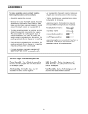
... final stage you have divided the assembly process into four stages. The parts needed for each stage are found in the drawings. • Tighten all parts as you assemble them, unless instructed to the weights. Cable Assembly-During this stage you will assemble the arms and the leg lever.... Place all parts in a cleared area and remove the packing materials. The Four ...
... final stage you have divided the assembly process into four stages. The parts needed for each stage are found in the drawings. • Tighten all parts as you assemble them, unless instructed to the weights. Cable Assembly-During this stage you will assemble the arms and the leg lever.... Place all parts in a cleared area and remove the packing materials. The Four ...

User Manual
Page 24
...and correct the problem. Before using the weight system, pull each cable a few times to make sure that all parts have been properly tightened. If one of this manual for proper cable routing. See the CABLE DIAGRAMS on page 28 of the cables does not move smoothly over the pulleys. IMPORTANT: If the...properly installed, they may be damaged when heavy weight is any slack in the cables, you will be explained in ADJUSTMENT, beginning on page 29. 24 See MAINTENANCE on the following page. The use of the remaining parts will need to the Curl Post (11) with two M6 x 16mm Screws ...
...and correct the problem. Before using the weight system, pull each cable a few times to make sure that all parts have been properly tightened. If one of this manual for proper cable routing. See the CABLE DIAGRAMS on page 28 of the cables does not move smoothly over the pulleys. IMPORTANT: If the...properly installed, they may be damaged when heavy weight is any slack in the cables, you will be explained in ADJUSTMENT, beginning on page 29. 24 See MAINTENANCE on the following page. The use of the remaining parts will need to the Curl Post (11) with two M6 x 16mm Screws ...
User Manual
Page 25
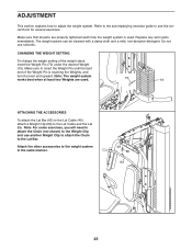
... To change the weight setting of the Weight Pin is used . 70 19 ATTACHING THE ACCESSORIES To attach the Lat Bar (63) to the Lat Cable (49), attach a Weight Clip (66) to the Lat Bar. Attach the other accessories to see the correct form for several exercises. Make sure to ...adjust the weight system. Replace any worn parts immediately. Do not use another Weight Clip to attach the Chain to the Lat Cable and the Lat Bar. ADJUSTMENT This section explains how to insert the Weight Pin until the bent end...
... To change the weight setting of the Weight Pin is used . 70 19 ATTACHING THE ACCESSORIES To attach the Lat Bar (63) to the Lat Cable (49), attach a Weight Clip (66) to the Lat Bar. Attach the other accessories to see the correct form for several exercises. Make sure to ...adjust the weight system. Replace any worn parts immediately. Do not use another Weight Clip to attach the Chain to the Lat Cable and the Lat Bar. ADJUSTMENT This section explains how to insert the Weight Pin until the bent end...
User Manual
Page 29
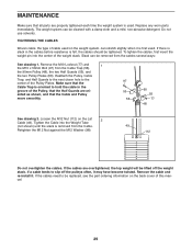
...the next closer hole to be removed from the cables several ways: See drawing 1. Remove the cable and re-install it may have become twisted. If the cables need to the center of the weight stack. Slack can be replaced, see the part ordering information on the weight system, can be ...lifted off the pulleys often, it . MAINTENANCE Make sure that all parts are properly tightened each time the weight ...
...the next closer hole to be removed from the cables several ways: See drawing 1. Remove the cable and re-install it may have become twisted. If the cables need to the center of the weight stack. Slack can be replaced, see the part ordering information on the weight system, can be ...lifted off the pulleys often, it . MAINTENANCE Make sure that all parts are properly tightened each time the weight ...

User Manual
Page 33
...47 3 V-pulley Bolt Brace 48 13 90mm Pulley 91 4 M6 x 60mm Button 7 1 Backrest Frame 49 1 Lat Cable Screw 8 1 Seat Frame 50 1 Butterfly Cable 92 2 M10 x 82mm Button 9 1 Frame 51 1 Leg Lever Cable Screw 10 1 Front Leg 52 1 Seat Adjustment 93 2 M10 x 110mm Bolt 11 1 Curl Post Knob 94 4 ... M10 x 75mm Bolt Cap 40 2 Press Arm Cap 83 5 M8 x 75mm Carriage * - For information about ordering replacement parts, see the back cover of this manual. *These parts are subject to change without notice. Qty. Description Key No. Description Key No. Exercise Guide Cap 84 5 M10 x 80mm...
...47 3 V-pulley Bolt Brace 48 13 90mm Pulley 91 4 M6 x 60mm Button 7 1 Backrest Frame 49 1 Lat Cable Screw 8 1 Seat Frame 50 1 Butterfly Cable 92 2 M10 x 82mm Button 9 1 Frame 51 1 Leg Lever Cable Screw 10 1 Front Leg 52 1 Seat Adjustment 93 2 M10 x 110mm Bolt 11 1 Curl Post Knob 94 4 ... M10 x 75mm Bolt Cap 40 2 Press Arm Cap 83 5 M8 x 75mm Carriage * - For information about ordering replacement parts, see the back cover of this manual. *These parts are subject to change without notice. Qty. Description Key No. Description Key No. Exercise Guide Cap 84 5 M10 x 80mm...


