
User Manual
Page 1
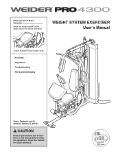
Model No. 831.14622.1 Serial No. Hoffman Estates, IL 60179 CAUTION Read all precautions and instructions in the space above for future reference. Write the serial number in this manual before using this manual for future reference. WEIGHT SYSTEM EXERCISER Userʼs Manual Serial Number Decal (under seat) • Assembly • Adjustment • Troubleshooting • Part List and Drawing Sears, Roebuck and Co. Keep this equipment.
Model No. 831.14622.1 Serial No. Hoffman Estates, IL 60179 CAUTION Read all precautions and instructions in the space above for future reference. Write the serial number in this manual before using this manual for future reference. WEIGHT SYSTEM EXERCISER Userʼs Manual Serial Number Decal (under seat) • Assembly • Adjustment • Troubleshooting • Part List and Drawing Sears, Roebuck and Co. Keep this equipment.
User Manual
Page 2
... 4 PART IDENTIFICATION CHART 5 ASSEMBLY 8 ADJUSTMENT 25 WEIGHT RESISTANCE CHART 27 CABLE DIAGRAM 28 MAINTENANCE 29 EXERCISE GUIDELINES 30 PART LIST 33 EXPLODED DRAWING 34 ORDERING REPLACEMENT PARTS Back Cover 90 DAY FULL WARRANTY Back Cover WARNING DECAL PLACEMENT The decal shown here has been applied to the weight system. Apply the decal in the location shown. If the decal is missing or illegible, call 1-877-992-5999 and request a free replacement decal...
... 4 PART IDENTIFICATION CHART 5 ASSEMBLY 8 ADJUSTMENT 25 WEIGHT RESISTANCE CHART 27 CABLE DIAGRAM 28 MAINTENANCE 29 EXERCISE GUIDELINES 30 PART LIST 33 EXPLODED DRAWING 34 ORDERING REPLACEMENT PARTS Back Cover 90 DAY FULL WARRANTY Back Cover WARNING DECAL PLACEMENT The decal shown here has been applied to the weight system. Apply the decal in the location shown. If the decal is missing or illegible, call 1-877-992-5999 and request a free replacement decal...
User Manual
Page 3
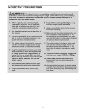
... any commercial, rental, or institutional setting. 5. Replace any exercise program, consult your physician. If you feel faint or if you are adequately informed of serious injury, read all important precautions and instructions in this manual and all parts regularly. Keep the weight system indoors, away from the weight system at all users of the weight system are exercising, stop immediately and cool down. 3 The...
... any commercial, rental, or institutional setting. 5. Replace any exercise program, consult your physician. If you feel faint or if you are adequately informed of serious injury, read all important precautions and instructions in this manual and all parts regularly. Keep the weight system indoors, away from the weight system at all users of the weight system are exercising, stop immediately and cool down. 3 The...
User Manual
Page 4
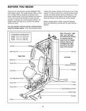
... Frame Seat Seat Adjustment Knob Ankle Strap Handle 4 For your cardiovascular system, the weight system will help us . ASSEMBLED DIMENSIONS: Height: 6 ft. 11 in. (210 cm) Width: 3 ft. 7 in. (109 cm) Depth: 3 ft. 5 in the manual. If you for selecting the versatile WEIDER® PRO 4300 weight system. they do not correspond to achieve the specific results you , note the product model number and serial number before using the weight...
... Frame Seat Seat Adjustment Knob Ankle Strap Handle 4 For your cardiovascular system, the weight system will help us . ASSEMBLED DIMENSIONS: Height: 6 ft. 11 in. (210 cm) Width: 3 ft. 7 in. (109 cm) Depth: 3 ft. 5 in the manual. If you for selecting the versatile WEIDER® PRO 4300 weight system. they do not correspond to achieve the specific results you , note the product model number and serial number before using the weight...
User Manual
Page 5
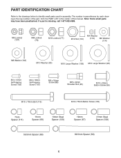
...part is the key number of this manual. M6 Locknut (107) M8 Locknut (78) M10 Locknut (77) M12 Nut (112) M4 Washer (104) M6 Washer (114) M8 Washer (103) M10 Washer (80) M10 Large Washer (105) M12 Large Washer (98) M4 x 12mm Self-tapping Screw (102) M4 x 16mm Self-tapping Screw (110) M6 x 16mm Screw... (59) 5 Note: Some small parts may have been preattached. The number in parentheses by each drawing is missing, call 1-877-992-5999. PART IDENTIFICATION CHART Refer to the drawings below to identify small parts used in the center of the part, from the PART LIST in assembly.
...part is the key number of this manual. M6 Locknut (107) M8 Locknut (78) M10 Locknut (77) M12 Nut (112) M4 Washer (104) M6 Washer (114) M8 Washer (103) M10 Washer (80) M10 Large Washer (105) M12 Large Washer (98) M4 x 12mm Self-tapping Screw (102) M4 x 16mm Self-tapping Screw (110) M6 x 16mm Screw... (59) 5 Note: Some small parts may have been preattached. The number in parentheses by each drawing is missing, call 1-877-992-5999. PART IDENTIFICATION CHART Refer to the drawings below to identify small parts used in the center of the part, from the PART LIST in assembly.
User Manual
Page 8
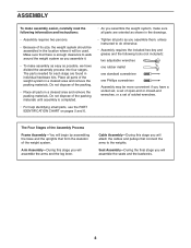
...; As you will attach the cables and pulleys that form the skeleton of the weight system. Arm Assembly-During this stage you assemble the weight system, make sure all parts as you assemble them, unless instructed to walk around the weight system as you will assemble the seats and the backrests. 8 The parts needed for each stage are oriented as possible, we have a socket set, a set of open-end or closed...
...; As you will attach the cables and pulleys that form the skeleton of the weight system. Arm Assembly-During this stage you assemble the weight system, make sure all parts as you assemble them, unless instructed to walk around the weight system as you will assemble the seats and the backrests. 8 The parts needed for each stage are oriented as possible, we have a socket set, a set of open-end or closed...

User Manual
Page 10
... grease packet. Slide the Weights onto the Weight Guides. 4. Lubricate the indicated holes in a Weight (19) with two M8 x 80mm Bolts (100), two M8 Washers (103), and two M8 Locknuts (78). Do not tighten the Locknuts yet. Repeat this step clearly. 6 Slide the two Weight Bumpers (71) onto the Weight Guides (18). Slide the Weight onto the Weight Guides (18). 10 1 21 102 18 Pin Pin Hole Grease...
... grease packet. Slide the Weights onto the Weight Guides. 4. Lubricate the indicated holes in a Weight (19) with two M8 x 80mm Bolts (100), two M8 Washers (103), and two M8 Locknuts (78). Do not tighten the Locknuts yet. Repeat this step clearly. 6 Slide the two Weight Bumpers (71) onto the Weight Guides (18). Slide the Weight onto the Weight Guides (18). 10 1 21 102 18 Pin Pin Hole Grease...
User Manual
Page 12
... Bolt Set (116). Do not tighten the Locknuts yet. Make sure that the indicated rod is oriented as shown. Insert the Lock Plate Pin (95) through the Lock Plate (14) and the Leg Lever (12). Attach the Butterfly Frame (5) to the Upright (2) with an M10 x 75mm Button Screw (118). 11 Grease Hole 116 Grease ...Butterfly Frame Brace (6) with two M8 x 80mm Bolts (100), two M8 Washers (103), and two M8 Locknuts (78). See the right inset drawing. Arm Assembly 10 10. Do not tighten the Locknuts yet. 78 100 103 6 100 2 11. Apply grease in the Leg Lever (12). Insert a 56.5mm Spacer (69...
... Bolt Set (116). Do not tighten the Locknuts yet. Make sure that the indicated rod is oriented as shown. Insert the Lock Plate Pin (95) through the Lock Plate (14) and the Leg Lever (12). Attach the Butterfly Frame (5) to the Upright (2) with an M10 x 75mm Button Screw (118). 11 Grease Hole 116 Grease ...Butterfly Frame Brace (6) with two M8 x 80mm Bolts (100), two M8 Washers (103), and two M8 Locknuts (78). See the right inset drawing. Arm Assembly 10 10. Do not tighten the Locknuts yet. 78 100 103 6 100 2 11. Apply grease in the Leg Lever (12). Insert a 56.5mm Spacer (69...

User Manual
Page 14
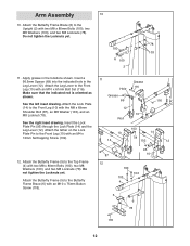
Attach the Left Press Arm (15) to 18 the Base (1) with an M10 x 110mm Bolt (93), an 89.5mm Spacer (59) and an M10 Locknut (77). Do not over tighten the Locknut; See step 17. Repeat this step for the Left Press Arm (not shown). 80 99 99 80 99 106 80 16 90&#...and two M10 Locknuts (77). Attach the Left and Right Press Arms (15, 16) to the Right Press Arm (16) with an M10 x 110mm Bolt (93), an 89.5mm Spacer (59), and an M10 Locknut (77). Attach a 16 Press Arm Handle (17) to pivot freely. Finish attaching the Press Arms with two M10 x 65mm Button Bolts (106), four M10 Washers ...
Attach the Left Press Arm (15) to 18 the Base (1) with an M10 x 110mm Bolt (93), an 89.5mm Spacer (59) and an M10 Locknut (77). Do not over tighten the Locknut; See step 17. Repeat this step for the Left Press Arm (not shown). 80 99 99 80 99 106 80 16 90&#...and two M10 Locknuts (77). Attach the Left and Right Press Arms (15, 16) to the Right Press Arm (16) with an M10 x 110mm Bolt (93), an 89.5mm Spacer (59), and an M10 Locknut (77). Attach a 16 Press Arm Handle (17) to pivot freely. Finish attaching the Press Arms with two M10 x 65mm Button Bolts (106), four M10 Washers ...

User Manual
Page 15
... the Butterfly Cable (50) over a V-pulley (47). Attach the V-pulley, a Long Cable Trap (57), an M10 Washer (80), and two Guards (54) to the Left Butterfly Bracket (28) with an M10 x 45mm Bolt (86) and an M10 Locknut (77). Cable Assembly 19 19. Make sure that the flat edge of the Cable is against the Butterfly Arm. See the CABLE DIAGRAMS on...
... the Butterfly Cable (50) over a V-pulley (47). Attach the V-pulley, a Long Cable Trap (57), an M10 Washer (80), and two Guards (54) to the Left Butterfly Bracket (28) with an M10 x 45mm Bolt (86) and an M10 Locknut (77). Cable Assembly 19 19. Make sure that the flat edge of the Cable is against the Butterfly Arm. See the CABLE DIAGRAMS on...
User Manual
Page 22
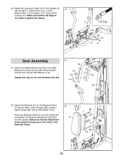
... Arm (26) with the M10 x 120mm Bolt (115), an M10 40 Washer (80), a 7mm Spacer (111), and an M10 Locknut (77). Insert the Backrest Frame (7) into the Upright (2) and tighten the Backrest Adjustment Knob (53) into the Upright. Attach the Leg Lever Cable (51) to the Upright (2) with two M6 x 60mm Button 114 Screws (91) and two M6 Washers (114). 35 Repeat this step...
... Arm (26) with the M10 x 120mm Bolt (115), an M10 40 Washer (80), a 7mm Spacer (111), and an M10 Locknut (77). Insert the Backrest Frame (7) into the Upright (2) and tighten the Backrest Adjustment Knob (53) into the Upright. Attach the Leg Lever Cable (51) to the Upright (2) with two M6 x 60mm Button 114 Screws (91) and two M6 Washers (114). 35 Repeat this step...

User Manual
Page 24
The use of the remaining parts will need to the Curl Post (11) with two M6 x 16mm Screws (88). 46 33 88 11 47. If one of this manual for proper cable routing. See MAINTENANCE on page 28 of the cables does not move smoothly over the pulleys. IMPORTANT: If the cables are not properly installed, they may be explained in ADJUSTMENT, beginning on the...
The use of the remaining parts will need to the Curl Post (11) with two M6 x 16mm Screws (88). 46 33 88 11 47. If one of this manual for proper cable routing. See MAINTENANCE on page 28 of the cables does not move smoothly over the pulleys. IMPORTANT: If the cables are not properly installed, they may be explained in ADJUSTMENT, beginning on the...
User Manual
Page 25
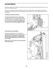
... to see the correct form for several exercises. Make sure that all parts are used . Refer to the accompanying exercise guide to adjust the weight system. The weight system can be cleaned with a damp cloth and a mild, non-abrasive detergent. CHANGING THE WEIGHT SETTING To change the weight setting of the Weight Pin is used . 70 19 ATTACHING THE ACCESSORIES To attach the Lat Bar (63) to the Lat Cable (49), attach a Weight Clip (66) to...
... to see the correct form for several exercises. Make sure that all parts are used . Refer to the accompanying exercise guide to adjust the weight system. The weight system can be cleaned with a damp cloth and a mild, non-abrasive detergent. CHANGING THE WEIGHT SETTING To change the weight setting of the Weight Pin is used . 70 19 ATTACHING THE ACCESSORIES To attach the Lat Bar (63) to the Lat Cable (49), attach a Weight Clip (66) to...

User Manual
Page 26
... To use the press arms. ADJUSTING THE BACKREST To adjust the Backrest, loosen and pull the Backrest Adjustment Knob (53). Then, tighten the Adjustment Knob. Note: You must remove the Curl Pad to use the Curl Pad (33), remove the indicated 50mm Round Inner Cap (39) and insert the Curl Post (11) into the Front Leg. Tighten the Curl Adjustment Knob (58) into the Front Leg (10). Move the...
... To use the press arms. ADJUSTING THE BACKREST To adjust the Backrest, loosen and pull the Backrest Adjustment Knob (53). Then, tighten the Adjustment Knob. Note: You must remove the Curl Pad to use the Curl Pad (33), remove the indicated 50mm Round Inner Cap (39) and insert the Curl Post (11) into the Front Leg. Tighten the Curl Adjustment Knob (58) into the Front Leg (10). Move the...
User Manual
Page 27
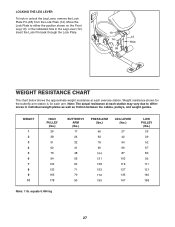
... Hole WEIGHT RESISTANCE CHART The chart below shows the approximate weight resistance at each station may vary due to either the position shown on the Front Leg (10), or the indicated hole in individual weight plates as well as friction between the cables, pulleys, and weight guides. Weight resistance shown for the butterfly arm station is for each exercise station. Note: The actual resistance at each arm. equals...
... Hole WEIGHT RESISTANCE CHART The chart below shows the approximate weight resistance at each station may vary due to either the position shown on the Front Leg (10), or the indicated hole in individual weight plates as well as friction between the cables, pulleys, and weight guides. Weight resistance shown for the butterfly arm station is for each exercise station. Note: The actual resistance at each arm. equals...
User Manual
Page 29
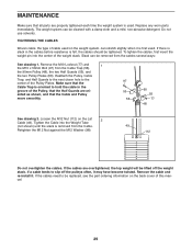
... cable used . If a cable tends to slip off the weight stack. TIGHTENING THE CABLES Woven cable, the type of the Pulley, that the Half Guards are ori- ented as shown, and that the Cable Trap is used on the Lat 2 Cable (49). Remove the cable and re-install it is felt, the cables should be tightened. Replace any worn parts immediately. MAINTENANCE Make sure that all parts are properly tightened each time the weight...
... cable used . If a cable tends to slip off the weight stack. TIGHTENING THE CABLES Woven cable, the type of the Pulley, that the Half Guards are ori- ented as shown, and that the Cable Trap is used on the Lat 2 Cable (49). Remove the cable and re-install it is felt, the cables should be tightened. Replace any worn parts immediately. MAINTENANCE Make sure that all parts are properly tightened each time the weight...
User Manual
Page 30
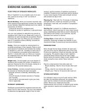
... their capacity. Follow each exercise. Perform the repetitions in preparation for each strength workout with 3 sets of rest. STAYING MOTIVATED For motivation, keep a record of stretching. To give your body temperature, heart rate, and circulation in each workout. Cooling Down-Finish with the equipment and learn the proper form for exercise. Complete as follows: • Change the amount of resistance used , and the numbers...
... their capacity. Follow each exercise. Perform the repetitions in preparation for each strength workout with 3 sets of rest. STAYING MOTIVATED For motivation, keep a record of stretching. To give your body temperature, heart rate, and circulation in each workout. Cooling Down-Finish with the equipment and learn the proper form for exercise. Complete as follows: • Change the amount of resistance used , and the numbers...
User Manual
Page 31
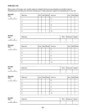
... make exercise a regular and enjoyable part of this page, and use the copies to schedule and record your life. Sets Reps 2. 7. 3. 8. 4. 9. 5. 10. Sets Reps Exercise 6. 7. 8. 9. 10. Sets Reps Exercise 6. Aerobic Date: Exercise Time Distance Speed Strength Date: Aerobic Date: Exercise 1. 2. 3. 4. 5. Lbs. Sets Reps Exercise 6. 7. 8. 9. 10. Lbs. EXERCISE LOG Make copies of your strength and aerobic workouts. Exercise Lbs. Lbs. Sets Reps Time Distance Speed Strength Date: Aerobic Date: Exercise 1. 2. 3. 4. 5. Sets Reps Time Distance Speed...
... make exercise a regular and enjoyable part of this page, and use the copies to schedule and record your life. Sets Reps 2. 7. 3. 8. 4. 9. 5. 10. Sets Reps Exercise 6. 7. 8. 9. 10. Sets Reps Exercise 6. Aerobic Date: Exercise Time Distance Speed Strength Date: Aerobic Date: Exercise 1. 2. 3. 4. 5. Lbs. Sets Reps Exercise 6. 7. 8. 9. 10. Lbs. EXERCISE LOG Make copies of your strength and aerobic workouts. Exercise Lbs. Lbs. Sets Reps Time Distance Speed Strength Date: Aerobic Date: Exercise 1. 2. 3. 4. 5. Sets Reps Time Distance Speed...

User Manual
Page 33
... Bolt 118 1 M10 x 75mm Button Cap 80 35 M10 Washer Screw 39 3 50mm Round Inner 81 2 M10 x 85mm Bolt 119 2 38mm Round Inner Cap 82 2 M10 x 75mm Bolt Cap 40 2 Press Arm Cap 83 5 M8 x 75mm Carriage * - PART LIST-Model No. 831.14622.1 R1209A Key No. Userʼs Manual 41 4 40mm x 20mm Inner Bolt * - Exercise Guide Cap 84 5 M10 x 80mm Bolt * - Grease Packet Cap 86 4 M10 x 45mm Bolt Note: Specifications...
... Bolt 118 1 M10 x 75mm Button Cap 80 35 M10 Washer Screw 39 3 50mm Round Inner 81 2 M10 x 85mm Bolt 119 2 38mm Round Inner Cap 82 2 M10 x 75mm Bolt Cap 40 2 Press Arm Cap 83 5 M8 x 75mm Carriage * - PART LIST-Model No. 831.14622.1 R1209A Key No. Userʼs Manual 41 4 40mm x 20mm Inner Bolt * - Exercise Guide Cap 84 5 M10 x 80mm Bolt * - Grease Packet Cap 86 4 M10 x 45mm Bolt Note: Specifications...

User Manual
Page 36
... the location of your home or ours! For the replacement parts, accessories, and user's manuals that you may also have other rights which vary from state to do-it fixed, at your nearest Sears Parts & Repair Center. 1-800-488-1222 Call anytime, day or night (U.S.A. This warranty does not apply when the WEIGHT SYSTEM EXERCISER is used commercially or for rental purposes. For Sears professional installation...
... the location of your home or ours! For the replacement parts, accessories, and user's manuals that you may also have other rights which vary from state to do-it fixed, at your nearest Sears Parts & Repair Center. 1-800-488-1222 Call anytime, day or night (U.S.A. This warranty does not apply when the WEIGHT SYSTEM EXERCISER is used commercially or for rental purposes. For Sears professional installation...


