

Uk Manual
Page 1
Serial Number Decal QUESTIONS? If you have questions, or if there are missing parts, please contact us: Call: 08457 089 009 From Ireland: 00 (44) 53 9236102 Website: www.iconsupport.eu E-mail: [email protected] Write: ICON Health & Fitness, Ltd. Keep this equipment. USERʼS MANUAL www.iconeurope.com Model No. c/o HI Group PLC Express Way Whitwood, West Yorkshire WF10 5QJ UK CAUTION Read all precautions and instructions in the space above for future reference. WEEVBE1409.0 Serial No. Write the serial number in this manual before using this manual for reference.
Serial Number Decal QUESTIONS? If you have questions, or if there are missing parts, please contact us: Call: 08457 089 009 From Ireland: 00 (44) 53 9236102 Website: www.iconsupport.eu E-mail: [email protected] Write: ICON Health & Fitness, Ltd. Keep this equipment. USERʼS MANUAL www.iconeurope.com Model No. c/o HI Group PLC Express Way Whitwood, West Yorkshire WF10 5QJ UK CAUTION Read all precautions and instructions in the space above for future reference. WEEVBE1409.0 Serial No. Write the serial number in this manual before using this manual for reference.
Uk Manual
Page 2
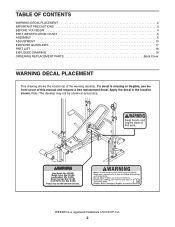
TABLE OF CONTENTS WARNING DECAL PLACEMENT 2 IMPORTANT PRECAUTIONS 3 BEFORE YOU BEGIN 4 PART IDENTIFICATION CHART 5 ASSEMBLY 6 ADJUSTMENT 13 EXERCISE GUIDELINES 17 PART LIST 18 EXPLODED DRAWING 19 ORDERING REPLACEMENT PARTS Back Cover WARNING DECAL PLACEMENT This drawing shows the location(s) of this manual and request a free replacement decal. If a decal is a registered trademark of ICON IP, Inc. 2 Apply the decal in the location shown. Note: The decal(s) may not be shown at actual size. WEIDER is missing or illegible, see the front cover of the warning decal(s).
TABLE OF CONTENTS WARNING DECAL PLACEMENT 2 IMPORTANT PRECAUTIONS 3 BEFORE YOU BEGIN 4 PART IDENTIFICATION CHART 5 ASSEMBLY 6 ADJUSTMENT 13 EXERCISE GUIDELINES 17 PART LIST 18 EXPLODED DRAWING 19 ORDERING REPLACEMENT PARTS Back Cover WARNING DECAL PLACEMENT This drawing shows the location(s) of this manual and request a free replacement decal. If a decal is a registered trademark of ICON IP, Inc. 2 Apply the decal in the location shown. Note: The decal(s) may not be shown at actual size. WEIDER is missing or illegible, see the front cover of the warning decal(s).

Uk Manual
Page 3
... precautions and instructions in this manual and all warnings on each fly arm. The weight bench is the responsibility of the barbell and secure the barbell with pre-existing health problems. 2. When using it . 6. It is designed to reduce the chances that all users of the weight bench are adequately informed of all precautions. 4. Replace any exercise program, consult your barbell when using the leg lever, place...
... precautions and instructions in this manual and all warnings on each fly arm. The weight bench is the responsibility of the barbell and secure the barbell with pre-existing health problems. 2. When using it . 6. It is designed to reduce the chances that all users of the weight bench are adequately informed of all precautions. 4. Replace any exercise program, consult your barbell when using the leg lever, place...
Uk Manual
Page 4
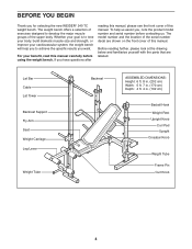
... exercises designed to achieve the specific results you for selecting the new WEIDER® 240 TC weight bench. For your cardiovascular system, the weight bench will help us . The weight bench offers a selection of the upper body. Lat Bar Cable Lat Tower Backrest Support Fly Arm Seat Weight Carriage Leg Lever Weight Tube Backrest ASSEMBLED DIMENSIONS: Height: 6 ft. 8 in. (202 cm) Width: 5 ft. 7 in. (170 cm) Depth: 4 ft. 4 in. (132 cm) Barbell Hook Weight Rest Upright Knob...
... exercises designed to achieve the specific results you for selecting the new WEIDER® 240 TC weight bench. For your cardiovascular system, the weight bench will help us . The weight bench offers a selection of the upper body. Lat Bar Cable Lat Tower Backrest Support Fly Arm Seat Weight Carriage Leg Lever Weight Tube Backrest ASSEMBLED DIMENSIONS: Height: 6 ft. 8 in. (202 cm) Width: 5 ft. 7 in. (170 cm) Depth: 4 ft. 4 in. (132 cm) Barbell Hook Weight Rest Upright Knob...
Uk Manual
Page 5
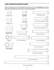
... (34, 66) M10 x 70mm Bolt (71) M10 x 54mm Bolt Set (56) M10 x 130mm Bolt (58) M10 x 170mm Bolt (60) 5 IMPORTANT: If you cannot find a part in the hardware kit, check to identify small parts used in parentheses by each drawing is the key number of the part, from the PART LIST near the end of this manual. The number in assembly. PART IDENTIFICATION CHART Refer to the drawings...
... (34, 66) M10 x 70mm Bolt (71) M10 x 54mm Bolt Set (56) M10 x 130mm Bolt (58) M10 x 170mm Bolt (60) 5 IMPORTANT: If you cannot find a part in the hardware kit, check to identify small parts used in parentheses by each drawing is the key number of the part, from the PART LIST near the end of this manual. The number in assembly. PART IDENTIFICATION CHART Refer to the drawings...
Uk Manual
Page 6
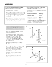
... the nut is enough clearance to walk around the weight bench as you have a socket set, a set of open-end or closed-end wrenches, or a set of its weight and size, the weight bench should be used. Attach the Crossbar (12) to the Right Base (5) in the position shown. Attach the Left Upright to the Left Upright (6) with two M10 x 65mm Bolts (55), two M10 2 Black Washers...
... the nut is enough clearance to walk around the weight bench as you have a socket set, a set of open-end or closed-end wrenches, or a set of its weight and size, the weight bench should be used. Attach the Crossbar (12) to the Right Base (5) in the position shown. Attach the Left Upright to the Left Upright (6) with two M10 x 65mm Bolts (55), two M10 2 Black Washers...
Uk Manual
Page 7
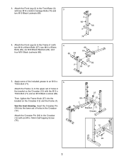
... Attach the Crossbar Pin (29) to the Frame (1) with two M10 x 52mm Carriage Bolts (74) and 3 two M10 Black Locknuts (66). 2 66 66 3 74 4. Then, tighten the Frame Knob (37) into the lower set of the included grease to the Front Base (3) with 4 two M10 x 60mm Bolts (57), two M10 x 55mm 66 1 Bolts (...66). 64 66 64 59 2 64 57 5. 3. See the inset drawing. Attach the Front Leg (2) to the Crossbar (12) with the M10 x 70mm Bolt (71) and an M10 Black Locknut (66). Attach the Front Leg (2) to an M10 x 5 70mm Bolt (71). Apply some of holes in the Crossbar (12).
... Attach the Crossbar Pin (29) to the Frame (1) with two M10 x 52mm Carriage Bolts (74) and 3 two M10 Black Locknuts (66). 2 66 66 3 74 4. Then, tighten the Frame Knob (37) into the lower set of the included grease to the Front Base (3) with 4 two M10 x 60mm Bolts (57), two M10 x 55mm 66 1 Bolts (...66). 64 66 64 59 2 64 57 5. 3. See the inset drawing. Attach the Front Leg (2) to the Crossbar (12) with the M10 x 70mm Bolt (71) and an M10 Black Locknut (66). Attach the Front Leg (2) to an M10 x 5 70mm Bolt (71). Apply some of holes in the Crossbar (12).
Uk Manual
Page 8
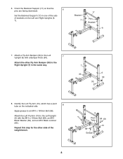
... (66). Attach the Left Fly Arm (10) to the Left Upright (6) with a Bumper Knob (50). 7 Attach the other side of brackets on the Left and Right Uprights (6, 7). Bracket 7 17 Pins Bracket 6 7. 6. Repeat this step for the other Fly Arm Bumper (30) to an M10 x 130mm Bolt (58). Orient the Backrest Support (17) so that the pins are facing downward. 6 Set the Backrest Support (17...
... (66). Attach the Left Fly Arm (10) to the Left Upright (6) with a Bumper Knob (50). 7 Attach the other side of brackets on the Left and Right Uprights (6, 7). Bracket 7 17 Pins Bracket 6 7. 6. Repeat this step for the other Fly Arm Bumper (30) to an M10 x 130mm Bolt (58). Orient the Backrest Support (17) so that the pins are facing downward. 6 Set the Backrest Support (17...

Uk Manual
Page 9
Tighten the M6 x 40mm Screws (62). 18 16 65 Holes 62 65 62 66 64 16 60 1 64 Grease 11. Make sure that the indi- 9 cated holes are in the location shown. See step 9. Attach the Seat (19) to the Frame (1) with the M10 x 170mm Bolt (60), two M10 Black Washers (64), and an M10 Black... Locknut (66). Do not tighten the Screws yet. 10. Orient the Backrest (18) and the Backrest Tubes (16...
Tighten the M6 x 40mm Screws (62). 18 16 65 Holes 62 65 62 66 64 16 60 1 64 Grease 11. Make sure that the indi- 9 cated holes are in the location shown. See step 9. Attach the Seat (19) to the Frame (1) with the M10 x 170mm Bolt (60), two M10 Black Washers (64), and an M10 Black... Locknut (66). Do not tighten the Screws yet. 10. Orient the Backrest (18) and the Backrest Tubes (16...

Uk Manual
Page 10
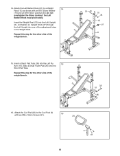
Next, press the Leg Lever Bumper (42) onto the Weight Tube (24). Insert a Long Pad Tube (54) into each end of an M10 x 54mm Bolt Set (56). Slide a Large Foam Pad (25) onto each Large Foam Pad. Attach the Weight Tube (24) to the barrel of the Long Pad Tube (54). Attach the Leg Lever (8) to the ...bracket on the Front Leg. 12 56 Bracket Grease 8 67 73 42 56 2 24 53 73 72 13. Make sure that the barrel of the Bolt Set is inserted through both sides of the bracket on the Front Leg (2) with the M10 x 54mm Bolt Set (56). Repeat this step with an...
Next, press the Leg Lever Bumper (42) onto the Weight Tube (24). Insert a Long Pad Tube (54) into each end of an M10 x 54mm Bolt Set (56). Slide a Large Foam Pad (25) onto each Large Foam Pad. Attach the Weight Tube (24) to the barrel of the Long Pad Tube (54). Attach the Leg Lever (8) to the ...bracket on the Front Leg. 12 56 Bracket Grease 8 67 73 42 56 2 24 53 73 72 13. Make sure that the barrel of the Bolt Set is inserted through both sides of the bracket on the Front Leg (2) with the M10 x 54mm Bolt Set (56). Repeat this step with an...
Uk Manual
Page 11
...adjustment holes in the Weight Rest. Repeat this step for the other side of the weight bench. 51 70 34 13 27 6 15. Attach the Curl Pad (20) to a Weight 14 Rest (13) as shown with two M6 x 16mm Screws (61). 16 20 9 61 11 14. Insert the Weight Rest (13) into the Left Upright (6), and tighten an Upright Knob... (27) through the Left Upright into the Left Fly 15 Arm (10). Repeat this step for the other side of the weight bench. 35...
...adjustment holes in the Weight Rest. Repeat this step for the other side of the weight bench. 51 70 34 13 27 6 15. Attach the Curl Pad (20) to a Weight 14 Rest (13) as shown with two M6 x 16mm Screws (61). 16 20 9 61 11 14. Insert the Weight Rest (13) into the Left Upright (6), and tighten an Upright Knob... (27) through the Left Upright into the Left Fly 15 Arm (10). Repeat this step for the other side of the weight bench. 35...

Uk Manual
Page 12
...Route the Cable (21) through the top of the Cable (21) onto the M10 x 20mm Bolt (63) and tighten an M10 Black Locknut (66) onto the Bolt. 66 64 52 22 Storage Hook 52 64 57 21 14 63 66 15 18. Next, wrap the Cable (21) over the Pulley (22), and attach the Pulley inside the Lat...Make sure that the Cable is under the storage hook. Slide the Weight Carriage (15) onto the Lat Tower (14). make sure that all remaining parts will be explained in ADJUSTMENT, starting on the Weight Carriage (15). 17. The use of all parts are properly tightened before you use the weight bench.
...Route the Cable (21) through the top of the Cable (21) onto the M10 x 20mm Bolt (63) and tighten an M10 Black Locknut (66) onto the Bolt. 66 64 52 22 Storage Hook 52 64 57 21 14 63 66 15 18. Next, wrap the Cable (21) over the Pulley (22), and attach the Pulley inside the Lat...Make sure that the Cable is under the storage hook. Slide the Weight Carriage (15) onto the Lat Tower (14). make sure that all remaining parts will be explained in ADJUSTMENT, starting on the Weight Carriage (15). 17. The use of all parts are properly tightened before you use the weight bench.
Uk Manual
Page 13
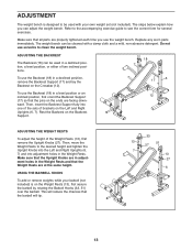
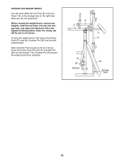
... on the Backrest Support. 18 7 17 6 12 ADJUSTING THE WEIGHT RESTS To adjust the height of two inclined positions. To use the weight bench. Do not use the Backrest (18) in the Weight Rests and that the Upright Knobs are facing downward. To use solvents to the desired height and tighten the Upright Knobs into the Left and Right Uprights (6, 7) and into one of the sets of brackets...
... on the Backrest Support. 18 7 17 6 12 ADJUSTING THE WEIGHT RESTS To adjust the height of two inclined positions. To use the weight bench. Do not use the Backrest (18) in the Weight Rests and that the Upright Knobs are facing downward. To use solvents to the desired height and tighten the Upright Knobs into the Left and Right Uprights (6, 7) and into one of the sets of brackets...

Uk Manual
Page 14
... a Weight Adapter (32) onto each Fly Arm (10, 11). 11 7 6 10 50 30 32 69 Weight USING THE LEG LEVER To use the Fly Arms (10, 11), slide the desired weights (not included) onto the weight tubes on the Leg Lever. Note: Before doing the bench press exercise, remove the Bumper Knobs (50) and the Fly Arm Bumpers (30) from the Uprights (6, 7) to balance the weight bench. 8 24 32 Weight 69...
... a Weight Adapter (32) onto each Fly Arm (10, 11). 11 7 6 10 50 30 32 69 Weight USING THE LEG LEVER To use the Fly Arms (10, 11), slide the desired weights (not included) onto the weight tubes on the Leg Lever. Note: Before doing the bench press exercise, remove the Bumper Knobs (50) and the Fly Arm Bumpers (30) from the Uprights (6, 7) to balance the weight bench. 8 24 32 Weight 69...

Uk Manual
Page 15
... the Lat Tower into the Front Leg, and tighten the Curl Knob (28) into the Front Leg and into one of the adjustment holes in the Curl Post. Note: When you are not using the Curl Pad (20), remove the Curl Post (9) and insert the 45mm Square Inner Cap (38) into the Front Leg (2). Secure the weights with the Cable Clip...
... the Lat Tower into the Front Leg, and tighten the Curl Knob (28) into the Front Leg and into one of the adjustment holes in the Curl Post. Note: When you are not using the Curl Pad (20), remove the Curl Post (9) and insert the 45mm Square Inner Cap (38) into the Front Leg (2). Secure the weights with the Cable Clip...
Uk Manual
Page 16
... Crossbar Pin (29) into the bracket. The Crossbar Pin will go. Next, raise the Front Leg (2) as far as it will prevent the weight bench from the indicated bracket. Before storing the weight bench, remove any weights, slide the Lat Tower (14) onto the storage tube, and adjust the Backrest (18) to the highest inclined position. Note: For clarity, the left fly arm is...
... Crossbar Pin (29) into the bracket. The Crossbar Pin will go. Next, raise the Front Leg (2) as far as it will prevent the weight bench from the indicated bracket. Before storing the weight bench, remove any weights, slide the Lat Tower (14) onto the storage tube, and adjust the Backrest (18) to the highest inclined position. Note: For clarity, the left fly arm is...
Uk Manual
Page 17
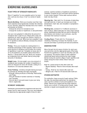
... enjoyable part of your body temperature, heart rate, and circulation in each week to give balance and variety to your workouts, vary the exercises from workout to a moderate percentage of their maximum capacity and progressively increase the intensity of your muscles near their capacity. Muscle Building-Work your exercise. Write the date, the exercises performed, the resistance used . • Change the number of repetitions or sets performed...
... enjoyable part of your body temperature, heart rate, and circulation in each week to give balance and variety to your workouts, vary the exercises from workout to a moderate percentage of their maximum capacity and progressively increase the intensity of your muscles near their capacity. Muscle Building-Work your exercise. Write the date, the exercises performed, the resistance used . • Change the number of repetitions or sets performed...
Uk Manual
Page 18
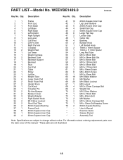
... manual. *These parts are subject to change without notice. PART LIST-Model No. Description 1 1 Frame 2 1 Front Leg 3 1 Front Base 4 1 Left Base 5 1 Right Base 6 1 Left Upright 7 1 Right Upright 8 1 Leg Lever 9 1 Curl Post 10 1 Left Fly Arm 11 1 Right Fly Arm 12 1 Crossbar 13 2 Weight Rest 14 1 Lat Tower 15 1 Weight Carriage 16 2 Backrest Tube 17 1 Backrest Support 18 1 Backrest 19 1 Seat 20 1 Curl Pad 21 1 Cable 22 1 Pulley 23 1 Lat Bar 24 1 Weight...
... manual. *These parts are subject to change without notice. PART LIST-Model No. Description 1 1 Frame 2 1 Front Leg 3 1 Front Base 4 1 Left Base 5 1 Right Base 6 1 Left Upright 7 1 Right Upright 8 1 Leg Lever 9 1 Curl Post 10 1 Left Fly Arm 11 1 Right Fly Arm 12 1 Crossbar 13 2 Weight Rest 14 1 Lat Tower 15 1 Weight Carriage 16 2 Backrest Tube 17 1 Backrest Support 18 1 Backrest 19 1 Seat 20 1 Curl Pad 21 1 Cable 22 1 Pulley 23 1 Lat Bar 24 1 Weight...
Uk Manual
Page 19
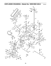
EXPLODED DRAWING-Model No. WEEVBE1409.0 R0909A 38 18 41 65 66 64 52 22 52 64 57 46 25 38 43 32 34 33 16 62 70 66 ...
EXPLODED DRAWING-Model No. WEEVBE1409.0 R0909A 38 18 41 65 66 64 52 22 52 64 57 46 25 38 43 32 34 33 16 62 70 66 ...
Uk Manual
Page 20
To help us assist you, be prepared to provide the following information when contacting us: • the model number and serial number of the product (see the front cover of this manual) • the name of the product (see the front cover of this manual) • the key number and description of the replacement part(s) (see the front cover of this manual. ORDERING REPLACEMENT PARTS To order replacement parts, please see the PART LIST and the EXPLODED DRAWING near the end of this manual) Part No. 279630 R0909A Printed in China © 2009 ICON IP, Inc.
To help us assist you, be prepared to provide the following information when contacting us: • the model number and serial number of the product (see the front cover of this manual) • the name of the product (see the front cover of this manual) • the key number and description of the replacement part(s) (see the front cover of this manual. ORDERING REPLACEMENT PARTS To order replacement parts, please see the PART LIST and the EXPLODED DRAWING near the end of this manual) Part No. 279630 R0909A Printed in China © 2009 ICON IP, Inc.


