
English Manual
Page 1
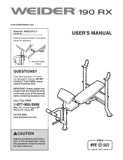
... limited warranty on the back cover of this manual) before using this manual for reference. Keep this equipment. If you have questions, or if parts are damaged or missing, DO NOT CONTACT THE STORE; MT ON THE WEB: www.weiderservice.com CAUTION Read all precautions and instructions in the space above for future reference. www.weidertness.com Model No. Serial Number...
... limited warranty on the back cover of this manual) before using this manual for reference. Keep this equipment. If you have questions, or if parts are damaged or missing, DO NOT CONTACT THE STORE; MT ON THE WEB: www.weiderservice.com CAUTION Read all precautions and instructions in the space above for future reference. www.weidertness.com Model No. Serial Number...
English Manual
Page 2
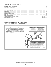
..., see the front cover of this manual and request a free replacement decal. Note: The decal(s) may not be shown at actual size. TABLE OF CONTENTS WARNING DECAL PLACEMENT 2 IMPORTANT PRECAUTIONS 3 BEFORE YOU BEGIN 4 PART IDENTIFICATION CHART 5 ASSEMBLY 6 ADJUSTMENT 11 EXERCISE GUIDELINES 13 PART LIST 14 EXPLODED DRAWING 15 ORDERING REPLACEMENT PARTS Back Cover LIMITED WARRANTY Back Cover WARNING DECAL PLACEMENT This drawing shows the location(s) of ICON IP, Inc. 2 Apply...
..., see the front cover of this manual and request a free replacement decal. Note: The decal(s) may not be shown at actual size. TABLE OF CONTENTS WARNING DECAL PLACEMENT 2 IMPORTANT PRECAUTIONS 3 BEFORE YOU BEGIN 4 PART IDENTIFICATION CHART 5 ASSEMBLY 6 ADJUSTMENT 11 EXERCISE GUIDELINES 13 PART LIST 14 EXPLODED DRAWING 15 ORDERING REPLACEMENT PARTS Back Cover LIMITED WARRANTY Back Cover WARNING DECAL PLACEMENT This drawing shows the location(s) of ICON IP, Inc. 2 Apply...
English Manual
Page 3
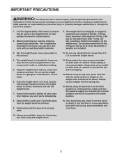
... and properly tighten all parts regularly. Always wear athletic shoes for home use the weight bench in this manual. 12. IMPORTANT PRECAUTIONS WARNING: To reduce the risk of serious injury, read all important precautions and instructions in any commercial, rental, or institutional setting. 5. Over exercising may result in an inclined position or a level position, make sure that the backrest support is inserted...
... and properly tighten all parts regularly. Always wear athletic shoes for home use the weight bench in this manual. 12. IMPORTANT PRECAUTIONS WARNING: To reduce the risk of serious injury, read all important precautions and instructions in any commercial, rental, or institutional setting. 5. Over exercising may result in an inclined position or a level position, make sure that the backrest support is inserted...
English Manual
Page 4
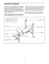
... model number and serial number before using the weight bench. The versatile 190 RX weight bench is to develop every major muscle group of this manual. Before reading further, please review the drawing below and familiarize yourself with the labeled parts. For your goal is designed to have questions after reading this manual, please see the front cover of the body. To help you to achieve the specific...
... model number and serial number before using the weight bench. The versatile 190 RX weight bench is to develop every major muscle group of this manual. Before reading further, please review the drawing below and familiarize yourself with the labeled parts. For your goal is designed to have questions after reading this manual, please see the front cover of the body. To help you to achieve the specific...
English Manual
Page 5
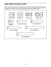
PART IDENTIFICATION CHART Use the drawings below each drawing is not in parentheses below to see if it has been preassembled. M6 Washer (26) M8 Washer (16) M8 Locknut (17) M10 Locknut (33) M6 x 16mm Screw (29) M6 x 35mm Screw (30) M8 x 45mm Bolt (15) M8 x 55mm Bolt (21) M8 x 75mm Bolt (18) M10 x 68mm Bolt (32) 5 Note: If a part is the key number of the part, from the PART LIST near the end of this manual. Extra parts may be included. The number in the hardware kit, check to identify the small parts needed for assembly.
PART IDENTIFICATION CHART Use the drawings below each drawing is not in parentheses below to see if it has been preassembled. M6 Washer (26) M8 Washer (16) M8 Locknut (17) M10 Locknut (33) M6 x 16mm Screw (29) M6 x 35mm Screw (30) M8 x 45mm Bolt (15) M8 x 55mm Bolt (21) M8 x 75mm Bolt (18) M10 x 68mm Bolt (32) 5 Note: If a part is the key number of the part, from the PART LIST near the end of this manual. Extra parts may be included. The number in the hardware kit, check to identify the small parts needed for assembly.
English Manual
Page 6
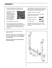
...;• Due to its weight and size, the weight bench should be assembled in a cleared area and remove the packing materials. ASSEMBLY •• To hire an authorized service technician to assemble this product, call 1-800-445-2480. •• To watch an assembly video, go to http://productvideo.co/ assembly/kmart/weider or use power tools. 1. To avoid damaging parts, do not tighten the Locknuts yet.
...;• Due to its weight and size, the weight bench should be assembled in a cleared area and remove the packing materials. ASSEMBLY •• To hire an authorized service technician to assemble this product, call 1-800-445-2480. •• To watch an assembly video, go to http://productvideo.co/ assembly/kmart/weider or use power tools. 1. To avoid damaging parts, do not tighten the Locknuts yet.

English Manual
Page 7
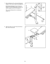
... 21 2 21 17 3. do not tighten the Locknuts yet. 3 2 15 16 16 17 8 4. Do not overtighten the Locknut; 2. Attach the Front Leg (8) to the Frame (2) with three M8 x 55mm Bolts (21), two M8 Washers 2 (16), and three M8 Locknuts (17) as shown; the Leg Lever must pivot easily. 33 4 Grease 32 8 7 Attach the Frame (2) to the Front...
... 21 2 21 17 3. do not tighten the Locknuts yet. 3 2 15 16 16 17 8 4. Do not overtighten the Locknut; 2. Attach the Front Leg (8) to the Frame (2) with three M8 x 55mm Bolts (21), two M8 Washers 2 (16), and three M8 Locknuts (17) as shown; the Leg Lever must pivot easily. 33 4 Grease 32 8 7 Attach the Frame (2) to the Front...

English Manual
Page 8
Attach the other Pad Tube (not shown) and the other two Foam Pads (23) in the Leg Lever (4). Slide a Foam Pad (23) onto each side of the Pad Tube. Holes 2 26 5 30 26 30 Pivot Rod 8 Orient the Backrest Tubes (5) as shown. 5. Insert a Pad Tube (10) into a hole in the same way. 5 23 4 10 23 23 23 6. Slide a Backrest Tube onto each side of the pivot rod on 6 the Frame (2). 6 Attach the Backrest (6) to the Backrest Tubes (5) with four M6 x 35mm Screws (30) and four M6 Washers (26). See steps 1–-3. Tighten the M8 Locknuts (17).
Attach the other Pad Tube (not shown) and the other two Foam Pads (23) in the Leg Lever (4). Slide a Foam Pad (23) onto each side of the Pad Tube. Holes 2 26 5 30 26 30 Pivot Rod 8 Orient the Backrest Tubes (5) as shown. 5. Insert a Pad Tube (10) into a hole in the same way. 5 23 4 10 23 23 23 6. Slide a Backrest Tube onto each side of the pivot rod on 6 the Frame (2). 6 Attach the Backrest (6) to the Backrest Tubes (5) with four M6 x 35mm Screws (30) and four M6 Washers (26). See steps 1–-3. Tighten the M8 Locknuts (17).
English Manual
Page 9
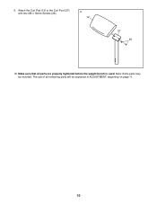
7. Attach the Seat (11) to the locked position, with four M6 x 16mm Screws (29). 8 11 1 Locking Pin 1 7 Locking Pin 2 29 9 Raise the Backrest (6), and insert the Backrest Support (7) into a set of holes in the Uprights (1). 7 See the inset drawing. Rotate the Backrest Support (7) to the Frame (2) with the locking pin wrapped around the left Upright (1). 6 1 Then, rest the Backrest (6) on the Backrest Support (7). 8.
7. Attach the Seat (11) to the locked position, with four M6 x 16mm Screws (29). 8 11 1 Locking Pin 1 7 Locking Pin 2 29 9 Raise the Backrest (6), and insert the Backrest Support (7) into a set of holes in the Uprights (1). 7 See the inset drawing. Rotate the Backrest Support (7) to the Frame (2) with the locking pin wrapped around the left Upright (1). 6 1 Then, rest the Backrest (6) on the Backrest Support (7). 8.
English Manual
Page 10
Note: Extra parts may be explained in ADJUSTMENT, beginning on page 11. 10 Make sure that all remaining parts will be included. 9. The use of all parts are properly tightened before the weight bench is used. Attach the Curl Pad (12) to the Curl Post (27) with two M6 x 16mm Screws (29). 9 12 27 29 10.
Note: Extra parts may be explained in ADJUSTMENT, beginning on page 11. 10 Make sure that all remaining parts will be included. 9. The use of all parts are properly tightened before the weight bench is used. Attach the Curl Pad (12) to the Curl Post (27) with two M6 x 16mm Screws (29). 9 12 27 29 10.
English Manual
Page 11
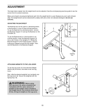
... three inclined positions. ADJUSTMENT The steps below explain how the weight bench can be used . Then, rest the Backrest on the weight rests to see the correct form for several exercises. Replace any of weights on the Crossbar (3). WARNING: When using the Leg Lever (4), place a barbell (not included) with the Spring Clip (19). See the accompanying exercise guide to balance the weight bench. To use solvents. ADJUSTING THE BACKREST...
... three inclined positions. ADJUSTMENT The steps below explain how the weight bench can be used . Then, rest the Backrest on the weight rests to see the correct form for several exercises. Replace any of weights on the Crossbar (3). WARNING: When using the Leg Lever (4), place a barbell (not included) with the Spring Clip (19). See the accompanying exercise guide to balance the weight bench. To use solvents. ADJUSTING THE BACKREST...
English Manual
Page 12
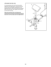
Then, tighten the Curl Knob (31) into the Front Leg (8), and align one of the adjustment holes in the Curl Post with the indicated hole in the Front Leg. When the Curl Pad (12) is not being used, remove the Curl Post (27) from the weight bench. 12 27 8 31 Hole 12 Store the Curl Post away from the Front Leg (8). Insert the Curl Post (27) into the Front Leg. ATTACHING THE CURL PAD For some exercises, the Curl Pad (12) must be attached to the weight bench.
Then, tighten the Curl Knob (31) into the Front Leg (8), and align one of the adjustment holes in the Curl Post with the indicated hole in the Front Leg. When the Curl Pad (12) is not being used, remove the Curl Post (27) from the weight bench. 12 27 8 31 Hole 12 Store the Curl Post away from the Front Leg (8). Insert the Curl Post (27) into the Front Leg. ATTACHING THE CURL PAD For some exercises, the Curl Pad (12) must be attached to the weight bench.
English Manual
Page 13
... the date, the exercises performed, the resistance used . •• Change the number of your workouts, vary the exercises from workout to 10 minutes of stretching and light exercise. A “"set . When you perform. Warming Up—-Start with 5 to workout. Cooling Down—-Finish with 5 to prevent post-exercise problems. Toning—-Tone your body’'s signals. Never hold your weight and key body measurements once a month...
... the date, the exercises performed, the resistance used . •• Change the number of your workouts, vary the exercises from workout to 10 minutes of stretching and light exercise. A “"set . When you perform. Warming Up—-Start with 5 to workout. Cooling Down—-Finish with 5 to prevent post-exercise problems. Toning—-Tone your body’'s signals. Never hold your weight and key body measurements once a month...
English Manual
Page 14
WEBE30112.0 R0812A Key No. Description Key No. Grease Packet * –- Qty. Qty. PART LIST Model No. For information about ordering replacement parts, see the back cover of this manual. *These parts are subject to change without notice. User’'s Manual Note: Specifications are not illustrated. 14 Exercise Poster * –- Description 1 2 Upright 2 1 Frame 3 1 Crossbar 4 1 Leg Lever 5 2 Backrest Tube 6 1 Backrest 7 1 Backrest Support 8 1 Front Leg 9 6 19mm Round Inner Cap 10 2 Pad Tube 11 1 Seat 12 1 Curl...
WEBE30112.0 R0812A Key No. Description Key No. Grease Packet * –- Qty. Qty. PART LIST Model No. For information about ordering replacement parts, see the back cover of this manual. *These parts are subject to change without notice. User’'s Manual Note: Specifications are not illustrated. 14 Exercise Poster * –- Description 1 2 Upright 2 1 Frame 3 1 Crossbar 4 1 Leg Lever 5 2 Backrest Tube 6 1 Backrest 7 1 Backrest Support 8 1 Front Leg 9 6 19mm Round Inner Cap 10 2 Pad Tube 11 1 Seat 12 1 Curl...
English Manual
Page 15
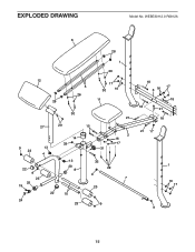
EXPLODED DRAWING Model No. WEBE30112.0 R0812A 12 28 6 5 26 28 1 26 17 30 16 11 30 27 29 9 13 23 4 22 9 23 25 19 22 24 14 33 13 20 8 10 23 21 15 2 16 17 31 32 29 9 7 23 9 18 3 16 17 18 18 21 18 21 17 1 16 17 9 15
EXPLODED DRAWING Model No. WEBE30112.0 R0812A 12 28 6 5 26 28 1 26 17 30 16 11 30 27 29 9 13 23 4 22 9 23 25 19 22 24 14 33 13 20 8 10 23 21 15 2 16 17 31 32 29 9 7 23 9 18 3 16 17 18 18 21 18 21 17 1 16 17 9 15

English Manual
Page 16
... limitation of this manual) •• the key number and description of the replacement part(s) (see the front cover of incidental or consequential damages. This warranty provides specic legal rights; Go to repairing or replacing, at ICON’'s option, the product through one of removal or installation; All repairs for which warranty claims are limited in their scope and duration to the customer. For in-home service...
... limitation of this manual) •• the key number and description of the replacement part(s) (see the front cover of incidental or consequential damages. This warranty provides specic legal rights; Go to repairing or replacing, at ICON’'s option, the product through one of removal or installation; All repairs for which warranty claims are limited in their scope and duration to the customer. For in-home service...


