
Maintenance Manual
Page 3
... providers to ensure the following safety precautions are adhered to use only the same model battery or an equivalent battery recommended by Toshiba. If you replace the battery pack or RTC battery, be sure to strictly. Improper repair of the computer may result in property damage... is not observed. Be sure to explode. Tecra A3/S2 Maintenance Manual iii WARNING: ......"Warning" indicates the existence of a hazard that could cause overheating, smoke or fire. Installation of the wrong battery can cause the battery to fasten screws securely with the right screwdriver....
... providers to ensure the following safety precautions are adhered to use only the same model battery or an equivalent battery recommended by Toshiba. If you replace the battery pack or RTC battery, be sure to strictly. Improper repair of the computer may result in property damage... is not observed. Be sure to explode. Tecra A3/S2 Maintenance Manual iii WARNING: ......"Warning" indicates the existence of a hazard that could cause overheating, smoke or fire. Installation of the wrong battery can cause the battery to fasten screws securely with the right screwdriver....
Maintenance Manual
Page 8
Chapter 4 Replacement Procedures 4.1 General ...4-1 4.2 Battery ...4-7 4.3 PC Card ...4-8 4.4 HDD ...4-9 4.5 Optical Drive Module...4-12 4.6 Optical Drive ...4-13 4.7 Wireless LAN...4-15 4.8 Expansion Memory ...4-17 4.9 Keyboard ...4-21 4.10 Bluetooth ...4-21 4.11 Modem...4-25 4.12 Display Assembly...4-26 4.13 Top Cover...4-28 4.14 Touch Pad...4-31 4.15 Speakers...4-32 4.16 System Board ...4-33 4.17 Direct Play buttom board 4-36 4.18 Fan, Hest & CPU...4-37 4.19 Display Mask...4-38 4.20 LCD Module...4-42 4.21 FL Inverter Board...4-44 viii Tecra A3/S2 Maintenance Manual
Chapter 4 Replacement Procedures 4.1 General ...4-1 4.2 Battery ...4-7 4.3 PC Card ...4-8 4.4 HDD ...4-9 4.5 Optical Drive Module...4-12 4.6 Optical Drive ...4-13 4.7 Wireless LAN...4-15 4.8 Expansion Memory ...4-17 4.9 Keyboard ...4-21 4.10 Bluetooth ...4-21 4.11 Modem...4-25 4.12 Display Assembly...4-26 4.13 Top Cover...4-28 4.14 Touch Pad...4-31 4.15 Speakers...4-32 4.16 System Board ...4-33 4.17 Direct Play buttom board 4-36 4.18 Fan, Hest & CPU...4-37 4.19 Display Mask...4-38 4.20 LCD Module...4-42 4.21 FL Inverter Board...4-44 viii Tecra A3/S2 Maintenance Manual
Maintenance Manual
Page 42
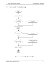
Y es Replace system board Y es Run diagnostic program (Procedure 4) Perform internal connection No check (Procedure 5) END Figure 2-2 Power Supply Troubleshooting Process Tecra A3/S2 Series Maintenance Manual 2-7 No Are the internal power connections secure? Y es Check power supply connections (Procedure 3) No Replace adaptor / battery (Procedure 2) Can you turn the computer on? 2.3 Power Supply Troubleshooting 2.3 Power Supply Troubleshooting START Check Power Supply Status (Procedure 1) 2 Troubleshooting Procedures Are the DC-IN and Battery LEDs lit?
Y es Replace system board Y es Run diagnostic program (Procedure 4) Perform internal connection No check (Procedure 5) END Figure 2-2 Power Supply Troubleshooting Process Tecra A3/S2 Series Maintenance Manual 2-7 No Are the internal power connections secure? Y es Check power supply connections (Procedure 3) No Replace adaptor / battery (Procedure 2) Can you turn the computer on? 2.3 Power Supply Troubleshooting 2.3 Power Supply Troubleshooting START Check Power Supply Status (Procedure 1) 2 Troubleshooting Procedures Are the DC-IN and Battery LEDs lit?
Maintenance Manual
Page 43
...be re-powered on without the AC power connected. The flowchart in discharging state 2-8 Tecra A3/S2 Series Maintenance Manual Table 2-1 Battery LED Battery State Charging Discharging LED colors Definition Amber, solid on for 1 second remaining every 4 seconds) Amber,...for 1 second minutes remaining. Green, solid on Battery fully charged by AC Green color off Battery not in the tables below. The procedures described in this section are: Procedure 1: Power status check Procedure 2: Adaptor / battery replacement Procedure 3: Power supply connection check Procedure 4: ...
...be re-powered on without the AC power connected. The flowchart in discharging state 2-8 Tecra A3/S2 Series Maintenance Manual Table 2-1 Battery LED Battery State Charging Discharging LED colors Definition Amber, solid on for 1 second remaining every 4 seconds) Amber,...for 1 second minutes remaining. Green, solid on Battery fully charged by AC Green color off Battery not in the tables below. The procedures described in this section are: Procedure 1: Power status check Procedure 2: Adaptor / battery replacement Procedure 3: Power supply connection check Procedure 4: ...
Maintenance Manual
Page 44
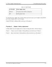
Procedure 2 Adaptor / battery replacement A faulty adaptor may not supply power or may not charge the battery. If the problem is still not resolved, go to Check 2. Tecra A3/S2 Series Maintenance Manual 2-9 No AC power exists. To check the power supply status, install a battery pack and connect an AC adaptor to the DC-IN port on Off...
Procedure 2 Adaptor / battery replacement A faulty adaptor may not supply power or may not charge the battery. If the problem is still not resolved, go to Check 2. Tecra A3/S2 Series Maintenance Manual 2-9 No AC power exists. To check the power supply status, install a battery pack and connect an AC adaptor to the DC-IN port on Off...

Maintenance Manual
Page 46
... Check 2. If a fuse is connected firmly, go to Check 3. Tecra A3/S2 Series Maintenance Manual 2-11 Run the Diagnostic test following procedures: 1. Attach the AC adaptor and turn on the system board are not blown. Replace it is blown, go to Check 3. Reinstall the battery pack. 2. If a fuse is not blown, go to make...
... Check 2. If a fuse is connected firmly, go to Check 3. Tecra A3/S2 Series Maintenance Manual 2-11 Run the Diagnostic test following procedures: 1. Attach the AC adaptor and turn on the system board are not blown. Replace it is blown, go to Check 3. Reinstall the battery pack. 2. If a fuse is not blown, go to make...
Maintenance Manual
Page 105
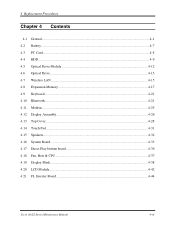
4 Replacement Procedures Chapter 4 Contents 4.1 General...4-1 4.2 Battery...4-7 4.3 PC Card...4-8 4.4 HDD...4-9 4.5 Optical Drive Module ...4-12 4.6 Optical Drive...4-13 4.7 Wireless LAN ...4-15 4.8 Expansion Memory...4-17 4.9 Keyboard...4-21 4.10 Bluetooth...4-21 4.11 Modem ...4-25 4.12 Display Assembly ...4-26 4.13 Top Cover ...4-28 4.14 Touch Pad ...4-31 4.15 Speakers ...4-32 4.16 System Board ...4-33 4.17 Direct Play buttom board 4-36 4.18 Fan, Hest & CPU ...4-37 4.19 Display Mask ...4-38 4.20 LCD Module ...4-42 4.21 FL Inverter Board ...4-44 Tecra A3/S2 Series Maintenance Manual 4-iii
4 Replacement Procedures Chapter 4 Contents 4.1 General...4-1 4.2 Battery...4-7 4.3 PC Card...4-8 4.4 HDD...4-9 4.5 Optical Drive Module ...4-12 4.6 Optical Drive...4-13 4.7 Wireless LAN ...4-15 4.8 Expansion Memory...4-17 4.9 Keyboard...4-21 4.10 Bluetooth...4-21 4.11 Modem ...4-25 4.12 Display Assembly ...4-26 4.13 Top Cover ...4-28 4.14 Touch Pad ...4-31 4.15 Speakers ...4-32 4.16 System Board ...4-33 4.17 Direct Play buttom board 4-36 4.18 Fan, Hest & CPU ...4-37 4.19 Display Mask ...4-38 4.20 LCD Module ...4-42 4.21 FL Inverter Board ...4-44 Tecra A3/S2 Series Maintenance Manual 4-iii
Maintenance Manual
Page 106
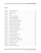
4 Replacement Procedures Figures Figure 4-1 Removing the battery pack 4-7 Figure 4-2 Removing a PC card 4-8 Figure 4-3 Installing a PC card 4-9 Figure 4-4 HDD ...4-9 Figure 4-5 Removing the HDD door 4-10 Figure 4-6 Removing the HDD Module 4-10 Figure 4-7 Removing ... screw of bottom 4-28 Figure 4-24 Removing the top cover 4-29 Figure 4-25 Removing FFC cable 4-29 Figure 4-26 Removing the speakers cable 4-30 4-iv Tecra A3/S2 Series Maintenance Manual
4 Replacement Procedures Figures Figure 4-1 Removing the battery pack 4-7 Figure 4-2 Removing a PC card 4-8 Figure 4-3 Installing a PC card 4-9 Figure 4-4 HDD ...4-9 Figure 4-5 Removing the HDD door 4-10 Figure 4-6 Removing the HDD Module 4-10 Figure 4-7 Removing ... screw of bottom 4-28 Figure 4-24 Removing the top cover 4-29 Figure 4-25 Removing FFC cable 4-29 Figure 4-26 Removing the speakers cable 4-30 4-iv Tecra A3/S2 Series Maintenance Manual
Maintenance Manual
Page 108
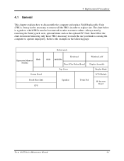
... to reach the one . It may not be removed in order to disassemble the computer and replace Field Replaceable Units (FRUs). 4 Replacement Procedures 4.1 General This chapter explains how to replace one you think is a guide to which FRUs need to be necessary to remove all the ... example on the following page. Battery pack Expansion Memory HDD Module System Board ODD MODEM Keyboard Direct Play Button Board Top Cover Wireless LAN Display Assembly Display Mask LCD Module Fan & Heat Sink CPU Speakers Touch Pad FL Inverter Board Tecra A3/S2 Series Maintenance Manual 4-1
... to reach the one . It may not be removed in order to disassemble the computer and replace Field Replaceable Units (FRUs). 4 Replacement Procedures 4.1 General This chapter explains how to replace one you think is a guide to which FRUs need to be necessary to remove all the ... example on the following page. Battery pack Expansion Memory HDD Module System Board ODD MODEM Keyboard Direct Play Button Board Top Cover Wireless LAN Display Assembly Display Mask LCD Module Fan & Heat Sink CPU Speakers Touch Pad FL Inverter Board Tecra A3/S2 Series Maintenance Manual 4-1
Maintenance Manual
Page 109
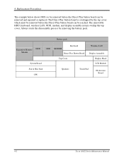
The Direct Play button board is overlapped by removing the battery pack. 4 Replacement Procedures The example below shows FRUs to be removed before the Direct Play button board can be reached. Battery pack Expansion Memory HDD Module ODD MODEM Keyboard Direct Play Button Board ...Wireless LAN Display Assembly System Board Top Cover Display Mask LCD Module Fan & Heat Sink CPU Speakers Touch Pad FL Inverter Board 4-2 Tecra A3/S2 Series Maintenance Manual...
The Direct Play button board is overlapped by removing the battery pack. 4 Replacement Procedures The example below shows FRUs to be removed before the Direct Play button board can be reached. Battery pack Expansion Memory HDD Module ODD MODEM Keyboard Direct Play Button Board ...Wireless LAN Display Assembly System Board Top Cover Display Mask LCD Module Fan & Heat Sink CPU Speakers Touch Pad FL Inverter Board 4-2 Tecra A3/S2 Series Maintenance Manual...
Maintenance Manual
Page 110
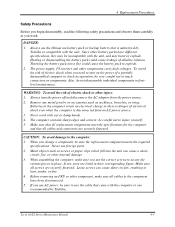
...disconnect the AC adaptor from an AC power source. 3. Never use the cable that came with the computer or one recommended by Toshiba or compatible with the unit. Always use AC power, be very careful not to the computer: 1. The computer contains sharp edges .... Loose screws can cause a short- Tecra A3/S2 Series Maintenance Manual 4-3 If you use the lithium ion battery pack or backup battery that all screws are listed in heat, smoke, or fire. 4. When assembling the computer, make sure all replacement components meet the specifications for the computer ...
...disconnect the AC adaptor from an AC power source. 3. Never use the cable that came with the computer or one recommended by Toshiba or compatible with the unit. Always use AC power, be very careful not to the computer: 1. The computer contains sharp edges .... Loose screws can cause a short- Tecra A3/S2 Series Maintenance Manual 4-3 If you use the lithium ion battery pack or backup battery that all screws are listed in heat, smoke, or fire. 4. When assembling the computer, make sure all replacement components meet the specifications for the computer ...
Maintenance Manual
Page 111
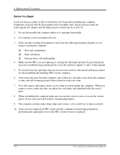
...the necessary troubleshooting and diagnostics tests described in chapters 2 and 3 of this section before you have replaced an FRU, make sure the computer is operating abnormally. 2. When you disassemble the computer. Begin each...section 4.2. 1. The computer contains many screws when you remove screws, make sure you have fixed or replaced. 4-4 Tecra A3/S2 Series Maintenance Manual Familiarize yourself with the correct parts. 8. Do not perform any operations that are... properly by removing the AC adaptor and the battery pack as instructed in their corresponding figures. 9.
...the necessary troubleshooting and diagnostics tests described in chapters 2 and 3 of this section before you have replaced an FRU, make sure the computer is operating abnormally. 2. When you disassemble the computer. Begin each...section 4.2. 1. The computer contains many screws when you remove screws, make sure you have fixed or replaced. 4-4 Tecra A3/S2 Series Maintenance Manual Familiarize yourself with the correct parts. 8. Do not perform any operations that are... properly by removing the AC adaptor and the battery pack as instructed in their corresponding figures. 9.
Maintenance Manual
Page 114
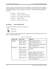
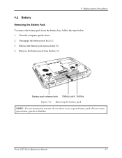
4 Replacement Procedures 4.2 Battery Removing the Battery Pack To remove the battery pack from the bay (3). 1 2 3 Battery pack release latch Battery pack Battery Figure 4-1 Removing the battery pack NOTE: For environmental reasons, do not throw away a spent battery pack. Please return spent battery packs to Toshiba. 2 1 Tecra A3/S2 Series Maintenance Manual 4-7 Turn the computer upside down. 2. Disengage the battery pack lock (1). 3. Release the battery pack release latch (2). 4. Remove the battery pack from the battery bay, follow the steps below. 1.
4 Replacement Procedures 4.2 Battery Removing the Battery Pack To remove the battery pack from the bay (3). 1 2 3 Battery pack release latch Battery pack Battery Figure 4-1 Removing the battery pack NOTE: For environmental reasons, do not throw away a spent battery pack. Please return spent battery packs to Toshiba. 2 1 Tecra A3/S2 Series Maintenance Manual 4-7 Turn the computer upside down. 2. Disengage the battery pack lock (1). 3. Release the battery pack release latch (2). 4. Remove the battery pack from the battery bay, follow the steps below. 1.
Maintenance Manual
Page 115
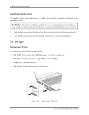
... a PC Card 4-8 Tecra A3/S2 Series Maintenance Manual Slide the battery pack into place, if necessary. The battery bay latch will click automatically. 2. Push the eject button once more to secure the installation. 4.3 PC Card Removing a PC Card To remove a PC Card, follow the steps below . 1. Use only batteries recommended by Toshiba as replacements. 1. The button pops...
... a PC Card 4-8 Tecra A3/S2 Series Maintenance Manual Slide the battery pack into place, if necessary. The battery bay latch will click automatically. 2. Push the eject button once more to secure the installation. 4.3 PC Card Removing a PC Card To remove a PC Card, follow the steps below . 1. Use only batteries recommended by Toshiba as replacements. 1. The button pops...
Maintenance Manual
Page 124
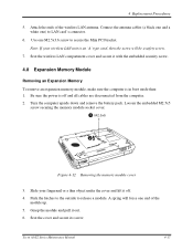
4 Replacement Procedures 5. Be sure the power is off . 4. Seat the cover and secure its screw. Tecra A3/S2 Series Maintenance Manual 4-17 Use one M2.5x3.6 screw to release a module. Grasp the module and pull it with the embedded security screw. 4.8 Expansion ... sure the computer is an 'A' type card, then the screw will force one ) to LAN card's connector. 6. Turn the computer upside down and remove the battery pack. Seat the wireless LAN compartment cover and secure it out. 6. Push the latches to the outside to secure the Mini PCI bracket. Attach the...
4 Replacement Procedures 5. Be sure the power is off . 4. Seat the cover and secure its screw. Tecra A3/S2 Series Maintenance Manual 4-17 Use one M2.5x3.6 screw to release a module. Grasp the module and pull it with the embedded security screw. 4.8 Expansion ... sure the computer is an 'A' type card, then the screw will force one ) to LAN card's connector. 6. Turn the computer upside down and remove the battery pack. Seat the wireless LAN compartment cover and secure it out. 6. Push the latches to the outside to secure the Mini PCI bracket. Attach the...
Maintenance Manual
Page 125
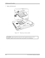
Replace the battery pack. 2 1 Latch Figure 4-13 Removing a memory module CAUTION: Do not touch the connectors on the expansion memory or on the connectors may cause memory access problems. 2 1 4-18 Tecra A3/S2 Series Maintenance Manual Debris on the computer. 4 Replacement Procedures 7.
Replace the battery pack. 2 1 Latch Figure 4-13 Removing a memory module CAUTION: Do not touch the connectors on the expansion memory or on the connectors may cause memory access problems. 2 1 4-18 Tecra A3/S2 Series Maintenance Manual Debris on the computer. 4 Replacement Procedures 7.
Maintenance Manual
Page 126
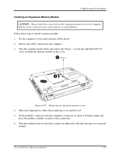
...the connectors may cause memory access problems. Follow these steps to install a memory module: 1. Remove all cables connected to ensure a firm connection. 6. Tecra A3/S2 Series Maintenance Manual 4-19 Set the computer to secure the module. Slide your fingernail or a thin object under the cover and lift it lies... at about a 45-degree angle and press the module carefully to the computer. 3. Push the module down and remove the battery. 4 Replacement Procedures Installing an Expansion Memory Module CAUTION: Do not touch the connectors on the expansion memory or on the computer.
...the connectors may cause memory access problems. Follow these steps to install a memory module: 1. Remove all cables connected to ensure a firm connection. 6. Tecra A3/S2 Series Maintenance Manual 4-19 Set the computer to secure the module. Slide your fingernail or a thin object under the cover and lift it lies... at about a 45-degree angle and press the module carefully to the computer. 3. Push the module down and remove the battery. 4 Replacement Procedures Installing an Expansion Memory Module CAUTION: Do not touch the connectors on the expansion memory or on the computer.
Maintenance Manual
Page 135
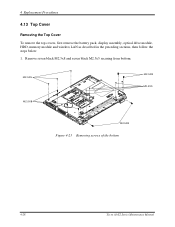
M2.5X5 M2.5X8 M2.5X5 M2.5X8 M2.5X8 Figure 4-23 Removing screws of the bottom 4-28 Tecra A3/S2 Series Maintenance Manual Remove seven black M2.5x8 and seven black M2.5x5 securing from bottom. 4 Replacement Procedures 4.13 Top Cover Removing the Top Cover To remove the top covers, first remove the battery pack, display assembly, optical drive module, HDD, memory module and wireless LAN as described in the preceding sections, then follow the steps below: 1.
M2.5X5 M2.5X8 M2.5X5 M2.5X8 M2.5X8 Figure 4-23 Removing screws of the bottom 4-28 Tecra A3/S2 Series Maintenance Manual Remove seven black M2.5x8 and seven black M2.5x5 securing from bottom. 4 Replacement Procedures 4.13 Top Cover Removing the Top Cover To remove the top covers, first remove the battery pack, display assembly, optical drive module, HDD, memory module and wireless LAN as described in the preceding sections, then follow the steps below: 1.

Maintenance Manual
Page 151
Secure one black M2x3 screw securing the FL invert board to the LCD display assembly. 4 Replacement Procedures 4.21 FL Inverter Board Removing the FL Inverter Board To remove the FL inverter board, first remove the battery pack, the display assembly, display mask, and LCD module, then follow the steps below . 1. M2x3 Figure 4-39... the figure in the preceding section. 1. Remove one black M2x3 screw connecting the FL inverter board to the LCD display assembly. 2. Reassemble the computer. 4-44 Tecra A3/S2 Series Maintenance Manual
Secure one black M2x3 screw securing the FL invert board to the LCD display assembly. 4 Replacement Procedures 4.21 FL Inverter Board Removing the FL Inverter Board To remove the FL inverter board, first remove the battery pack, the display assembly, display mask, and LCD module, then follow the steps below . 1. M2x3 Figure 4-39... the figure in the preceding section. 1. Remove one black M2x3 screw connecting the FL inverter board to the LCD display assembly. 2. Reassemble the computer. 4-44 Tecra A3/S2 Series Maintenance Manual

User Manual
Page 5
...These limits are designed to provide reasonable protection against harmful interference in this manual. ■ Replace only with the instructions, may be used in such case. Use only the battery pack that interference will not occur in a wet basement or near a bathtub, washing bowl...comply with the computer or an optional battery pack. FCC information Model Name: TECRA A3/S2 FCC notice "Declaration of wrong battery could void the user's authority to this equipment, not expressly approved by TOSHIBA or parties authorized by TOSHIBA is no liability for any damage ...
...These limits are designed to provide reasonable protection against harmful interference in this manual. ■ Replace only with the instructions, may be used in such case. Use only the battery pack that interference will not occur in a wet basement or near a bathtub, washing bowl...comply with the computer or an optional battery pack. FCC information Model Name: TECRA A3/S2 FCC notice "Declaration of wrong battery could void the user's authority to this equipment, not expressly approved by TOSHIBA or parties authorized by TOSHIBA is no liability for any damage ...


